SW6MA-S2100Wireless Microphone
Enping Misha Electronic Co., LtdApplication Details
- Equipment Class
- TBF - Licensed Broadcast Transmitter Held to Face
- Date of Grant
- Mar 20, 2005
- Application Purpose
- Original Equipment
- Date of Application
- Mar 20, 2005
- Equipment Note
- Wireless Microphone
- Frequency Range
- 199.49000000 - 199.49000000
- Country
- China
Documents & Files
Document Text
Text extracted from the exhibit documents filed with the FCC. Open a document above to read the original.
Users Manual
Taixing microphone using instruction .Operation of handhold microphone 1. Turn the microphone to “OFF” position, screw handhold microphone battery cover in counter-o’clock direction. Insert 9V battery, screw back the cover. 2. Turning the microphone to “ON” position, now the receiver “RF LED” indicating light on means the wireless microphone starting to work.. Turn the microphone to “OFF” position if don’t use. 3. If the indicating light of microphone darken evidently, that means the battery is less power, please change the new battery. .Remark: 1. Please avoid to place the receiver board under sunshine directly ,dusty place or moisture place and try to keep far away from the magnetic field. 2. Please avoid to place the receiver to dead corner in order to keep the good single. 3. Please take out the battery when the microphone not use for a long time so that it won’t worsen the microphone by the poor battery. 4. Please don’t throw the microphone so as to avoid the serious damage.
Block Diagram
Block Diagram
Cover Letter(s)
1 Mike Kuo From: Jimmy [[email protected]] Sent: Friday, March 18, 2005 8:15 PM To: Mike Kuo Subject: : ENPING MISHA ELECTRONIC CO.,LTD, FCC ID: SW6MA-S2100, Assessment NO.: AN05T4643, Notice#1 Attachments: user manual.pdf; Report.pdf; FCC ID Label and Location.pdf; calibration reports.pdf user manual.pdf (690 KB) Report.pdf (280 KB) FCC ID Label and Location.pdf ... calibration reports.pdf (2 MB)... Dear Mike, The following are responses to ENPING MISHA ELECTRONIC CO.,LTD, FCC ID: SW6MA-S2100, Assessment NO.: AN05T4643 Response to Question #1: New FCC ID Label and Location has been submitted. Response to Question #2: Sorry for making such a careless error while generating the test report, the revised test report have corrected these errors. The Calibration report of measurement instruments have been provided. Response to Question #3: Retest has been applied, all investigation shows that no compliance has been found and the test report has been revised correspondingly. Response to Question #4: The full edition of User Manual has been provided in attachment. Best wishes! Jimmy ---------- : Mike Kuo [mailto:[email protected]] : 2005316 10:42 : [email protected] : Jimmy : FW: ENPING MISHA ELECTRONIC CO.,LTD, FCC ID: SW6MA-S2100, Assessment NO.: AN05T4643, Notice#1 -----Original Message----- From: Compliance Certification Services [mailto:[email protected]] Sent: Tuesday, March 15, 2005 6:10 PM 2 To: Mike Kuo Subject: ENPING MISHA ELECTRONIC CO.,LTD, FCC ID: SW6MA-S2100, Assessment NO.: AN05T4643, Notice#1 Question #1: FCC ID label format does not comply with section 2.925(a)(1). The requirement for FCC ID should be " The FCC ID shall be preceded by the term FCC ID in capital letters on a single line.." The submitted FCC ID label the FCC ID and proposed ID is not on a single line. Please submit revised FCC ID label format. Question #2: As indicated in the test report, almost all the test equipments were calibrated on June 08, 2004. Please submit calibration certificates for the following measurement equipment: Spectrum Analyzer ADVANTEST R3132 N/A 06/08/2004 06/07/2005 EMI Test Receiver HP 8546A 3448A00232 06/08/2004 06/07/2005 Pre-Amplifier HP 8447D 2944A07999 06/08/2004 06/07/2005 Bi-Log Antenna EMCO 3142 9910-1436 06/08/2004 06/07/2005 Bi-Log Antenna SCHAFFNER CBL6143 5082 06/08/2004 06/07/2005 CABLE TIME Microwave LMR-400 N-TYPE04 06/08/2004 06/07/2005 Question #3: As shown on the spectrum plots and verified via the test equipment list, while performing section 5, 8 and 9 of test report, audio signal was not applied and the emission was not modulated. Please redo the tests with audio modulation and submit the plots. Question #4: Please submit complete user manual including receiver portion. Best Regards Mike Kuo The items indicated above must be submitted before processing can continue on the above referenced application. Failure to provide the requested information within 30 days of the original e-mail date may result in application dismissal and forfeiture of the filing fee. Also, please note that partial responses increase processing time and should not be submitted. Any questions about the content of this correspondence should be directed to the e-mail address listed below the name of the sender.
Cover Letter(s)
Power of Attorney
External Photos
Top View of EUT Bottom View of EUT Left View of EUT Right View of EUT Front View of EUT Back View of EUT
ID Label/Location Info
FCC ID Label and Location ENPING MISHA ELECTRONIC CO., LTD This device complies with Part 74 of FCC Rules FCC ID: SW6MA-S2100
Internal Photos
Inside photos-1 Inside photos-2 Inside photos-3
Operational Description
Transmitter working theory The MIC transform the sound into electronic signal, the signal then through C 2 coupling to network that consist C 3 and R 1 , and then through the two amplifer stages. The two amplifer stages consist of Q1,Q2 and so on. Enlarged audio signal then to the two pins of D1 through R9, the oscillating circuit consisting of transistor Q3, quartz crystal JT and other components. When the audio voltage changed then the voltage between two pins of D1 changed, and because the capacitance value of D1 is decided by its voltage so the capacitance of D1 will changed by the change of audio signal’s amplitude, the final result is the oscillating frequency will be modulated by the amplitude of audio signal. The circuit of selection frequency consist of C10 and T2 and produce 3 times’ frequency. Enlarged by amplifer stage that consist C12,Q4 and produce 2 times’ frequency by T3,C13, then the output of C15 through choosing network that consist L3,C16 and C17, then enlarged by amplifer stage that consist C18,Q5,C20,L4 and produce 2 times’ frequency, the frequency of signal change to 12 times’ original frequency totally through above processes. Then the high-frequency signal through C21, choosing frequency and transmitted out by antenna matching network C23 an L6.
Parts List/Tune Up Info
10SMT0603 47SMT0603 100SMT0603 150SMT0603 560SMT0603 1KSMT0603 1K8 SMT0603 2K2SMT0603 4K7SMT0603 5K6SMT0603 10KSMT0603 22K SMT0603 27KSMT0603 47K SMT0603 100KSMT06031 150KSMT0603 220K SMT0603 Regulated Diod 5V1 2PSMT0603 3PSMT06031 10PSMT0603 15PSMT0603 18PSMT0603 20PSMT0603 22PSMT0603 30PSMT0603 39PSMT0603 47PSMT0603 68PSMT0603 100PSMT0603 470PSMT0603 SMT0603 SMT0603 SMT0603 SMT0603 4.7uF/50V 10uF/50V 47uF/16V C9014 C1815 T33 KSP10 1uH 10uH 3.3uH Filter 3pins 10.7A Ceramic Capacitance Electronic Components luminum Capacitanc Transistor Component nameParametermodelQuantity used in RXQuantity used in TX Resistance Color Inductance Demodulator2pins 10.7G 78L05 CXA1691 4978L 70.0663MHz 16.6416MHz 3X4.5X0.6C 3X3.5X0.6A 3X8.5X0.6A 3X6.5X0.6A 3X3.5X0.6A 2X5 red 3red Socket of lamp 2pins Switch 306 Batter y 21001 TX RX IF transformer PCB Crystal LED Wires IC
Parts List/Tune Up Info
ADJUSTMENT PROCEDURES 1. Transmitter Power Adjustment a). Adjust the DC power supply so that 9.0V is obtained at the battery terminals. Confirm that the power meter, dummy load and output tester are prepared. b). Turn the power on and mount a JT element (16.6416MHz) into the crystal on the PCB board. c). Adjust T2, T3, L3, L4, L5 in this order so that the power meter reading become maximum. d). Repeat procedure c several times. The RF power meter reading should be more than 0.001W when the power is on and at a normal temperature. Then check the current meter reading should be less than 35mA. 2. Transmission Deviation Adjustment a). Set up the unit for the transmission mode. b). Adjust T1 so that the frequency counter reading is 199.5 MHz c). So that the maximum deviation is 5 KHz Adjustment setup block diagram
Test Report
COMPLIANCE CERTIFICATION SERVICES (SHENZHEN) INC. REPORT NO: SZE0501029 FCC ID: SW6MA-S2100 DATE: 02/26/2005 Page 1 of 32 Rev. 00 ELECTROMAGNETIC EMISSIONS COMPLIANCE REPORT INTENTIONAL RADIATOR CERTIFICATION TO FCC PART 74 SUBPART H REQUIREMENT OF wireless microphone MODEL NO.: MA-S2100 BRAND NAME: N/A FCC ID: SW6MA-S2100 REPORT NO:SZE0501029 ISSUE DATE: February 26, 2005 Prepared for ENPING MISHA ELECTRONIC CO., LTD PINGSHI DEVELOPMENT AREA ENPING CITY GUANGDONG CHINA Prepared by COMPLIANCE CERTIFICATION SERVICES (SHENZHEN) INC. d.b.a. COMPLIANCE CERTIFICATION SERVICES (SHENZHEN) INC. NO. 6, JINAO INDUSTRIAL PARK, NO. 35 JUKENG ROAD, DASHUIKENG VILLAGE, GUANLAN TOWN, BAOAN DISTRICT, SHENZHEN, CHINA TEL: 86-755-28055000 FAX: 86-755-28055221 COMPLIANCE CERTIFICATION SERVICES (SHENZHEN) INC REPORT NO: SZE0501029 FCC ID: SW6MA-S2100 DATE: 02/26/2005 Page 2 Rev. 00 VERIFICATION OF COMPLIANCE Applicant: ENPING MISHA ELECTRONIC CO., LTD PINGSHI DEVELOPMENT AREA ENPING CITY GUANGDONG CHINA Product Description: wireless microphone Brand Name: N/A Model Number: MA-S2100, MA-S500 Serial Number: N/A File Number: SZE0501029 Date of Test: January 20,2005 ~ February 25, 2005 We hereby certify that: The above equipment was tested by COMPLIANCE CERTIFICATION SERVICES (SHENZHEN) INC. The test data, data evaluation, test procedures, and equipment configurations shown in this report were made in accordance with the procedures given in TIA/EIA 603; ANSI C 63.4:2001 and the sample tested as described in this report is in compliance with the FCC Rules Part 74 Subpart H. The test results of this report relate only to the tested sample identified in this report. Approved By Reviewed By Clinton Kao / Q.A. Manager Jimmy COMPLIANCE CERTIFICATION COMPLIANCE CERTIFICATION SERVICES (SHENZHEN) INC. SERVICES (SHENZHEN) INC. COMPLIANCE CERTIFICATION SERVICES (SHENZHEN) INC REPORT NO: SZE0501029 FCC ID: SW6MA-S2100 DATE: 02/26/2005 Page 3 Rev. 00 Table of Contents 1. GENERAL INFORMATION .............................................4 2. SYSTEM TEST CONFIGURATION .............................................6 3. SUMMARY OF TEST RESULTS .............................................9 4. DESCRIPTION OF TEST MODES ..............................................9 5. MAXIMUM TRANSMITTER POWRE ..........................................10 6. MODULATION CHARACTERISTICS ..........................................13 7. FREQUENCY TOLERANCE .........................................17 8. EMISSION BANDWIDTH ...........................................20 9. UNWANTED RADIATION .............................................22 APPENDIX 1 PHOTOGRAPHS OF SETUP ..............................................27 APPENDIX 2 PHOTOGRAPHS OF EUT .............................................29 COMPLIANCE CERTIFICATION SERVICES (SHENZHEN) INC REPORT NO: SZE0501029 FCC ID: SW6MA-S2100 DATE: 02/26/2005 Page 4 Rev. 00 1. GENERAL INFORMATION 1.1 Product Description The ENPING MISHA ELECTRONIC CO., LTD Model: MA-S2100 (referred to as the EUT in this report). The EUT is a one channels Wireless Microphone designed as Low Power Auxiliary Stations for transmitting voice only. It is designed by way of utilizing the FM modulation achieves the system operating. A major technical descriptions of EUT is described as following: A). Frequency Tolerance: 0.002055% (0.005%) B). Communication Type: Voice/Tone only C). Modulation: AM D). Emission type: A3E E). Emission designator: 28K0A3E (2M, M=14, Necessary Bandwidth = 28 KHz) F). Emission Bandwidth: 155.0 KHz (Limit: 200 KHz) G).Peak Frequency Deviation: 6.85 KHz (Limit<75 KHz) H).Audio Frequency Response: 14 KHz I). Maximum Transmitter Power: 1.08 mW (Limit: 50 mW) J). Output power Modification: Fixed can’t be change K). Unwanted Radiation: 1). At least 50 dB (Limit 25 dB) on any frequency removed from the center of the authorized bandwidth by more than 50% up to and including 100% of the authorized bandwidth. 2). At least 55 dB (Limit 35 dB) on any frequency removed from the center of the authorized bandwidth by more than 100% up to and including 250% of the authorized bandwidth. 3). At least 35 dB (Limit 13.32 dB) on any frequency removed from the center of authorized bandwidth by more than 250%) L ). Antenna Designation: Integral M). Power Supply: 9 V dc by battery N). DC Voltage= 7.2V and DC Current= 15.2 mA into the final stage for normal operation over the power range O). Battery Endpoint: DC 7.2 V P). Operating Frequency Range and Channels Frequency Range: 199.49 MHz CH 01 ---- 199.49 MHz Q). Effective distance: 100M, with 1.08 mW power output COMPLIANCE CERTIFICATION SERVICES (SHENZHEN) INC REPORT NO: SZE0501029 FCC ID: SW6MA-S2100 DATE: 02/26/2005 Page 5 Rev. 00 1.2 Related Submittal(s) / Grant (s) This submittal(s) (test report) is intended for FCC DOC filing to comply with the FCC Part 74, Subpart H Rules. 1.3 Test Methodology The radiated emission testing was performed according to the procedures of ANSI TIA/EIA 603 and FCC CFR 47 2.1046, 2.1047, 2.1049, 2.1051, 2.1053, 2.1055 and 2.1057 1.4 Test Facility The open area test site used to collect the radiated data is located on the address of COMPLIANCE CERTIFICATION SERVICES (SHENZHEN) INC. No. 6, Jinao industrial park, No.35 Jukeng Road, Dashuikeng Village, Guanlan Town, Baoan District, Shenzhen, China. The Open Area Test Site is constructed and calibrated to meet the FCC requirements in documents ANSI C63.4: 2001 and CISPR 22/EN 55022 requirements. 1.5 Special Accessories Not available for this EUT intended for grant. 1.6 Equipment Modifications Not available for this EUT intended for grant. 1.7 Differences between Models Model Name Differences MA-S2100 No difference MA-S500 No difference COMPLIANCE CERTIFICATION SERVICES (SHENZHEN) INC REPORT NO: SZE0501029 FCC ID: SW6MA-S2100 DATE: 02/26/2005 Page 6 Rev. 00 2. System Test Configuration 2.1 EUT Configuration The EUT configuration for testing is installed on RF field strength measurement to meet the Commissio…
Text truncated - open the document above for the full version.
Test Setup Photos
COMPLIANCE CERTIFICATION SERVICES (SHENZHEN) INC REPORT NO: SZE0501029 FCC ID: SW6MA-S2100 DATE: 02/26/2005 Page 27 Rev. 00 APPENDIX 1 PHOTOGRAPHS OF SET UP COMPLIANCE CERTIFICATION SERVICES (SHENZHEN) INC REPORT NO: SZE0501029 FCC ID: SW6MA-S2100 DATE: 02/26/2005 Page 28 Rev. 00 Radiated Emission Setup Photo
Contact Information
Applicant
Jianning Liang(CEO)
Test Firm
Compliance Certification Services (Shenzhen) Inc.Clinton Kao
Technical Specifications
| # | Rule Parts | Frequency Range | Power Output | Emission | Tolerance |
|---|---|---|---|---|---|
| 1 | 74.861 | 199.49 MHz - 199.49 MHz | 1.00 mW | 28K0A3E | 0.0050000000 % |
Other Applications from Enping Misha Electronic Co., Ltd

SW6MIC200
Aug 25, 2021Wireless Microphone
Equipment Class
DWM - Part 15 Wireless Microphone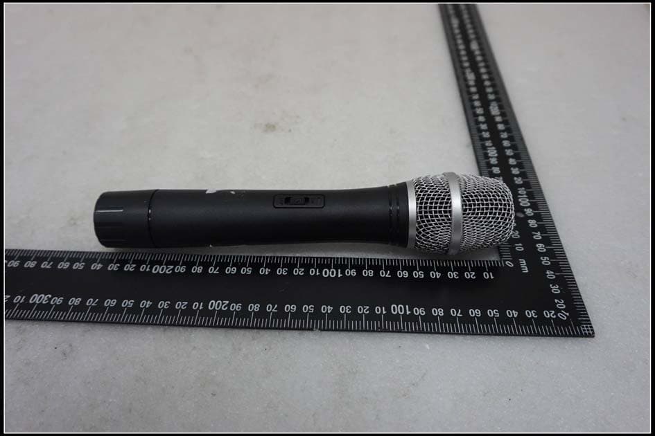
SW6TWM301
Nov 11, 2015Wireless microphone
Equipment Class
TBF - Licensed Broadcast Transmitter Held to Face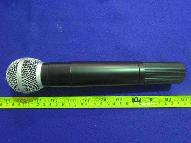
SW6MA-338
Sep 29, 2015Wireless microphone
Equipment Class
TBF - Licensed Broadcast Transmitter Held to Face