SY5HOCFGE00CARD ASSY ENTRY KEY
Continental Automotive Korea Ltd.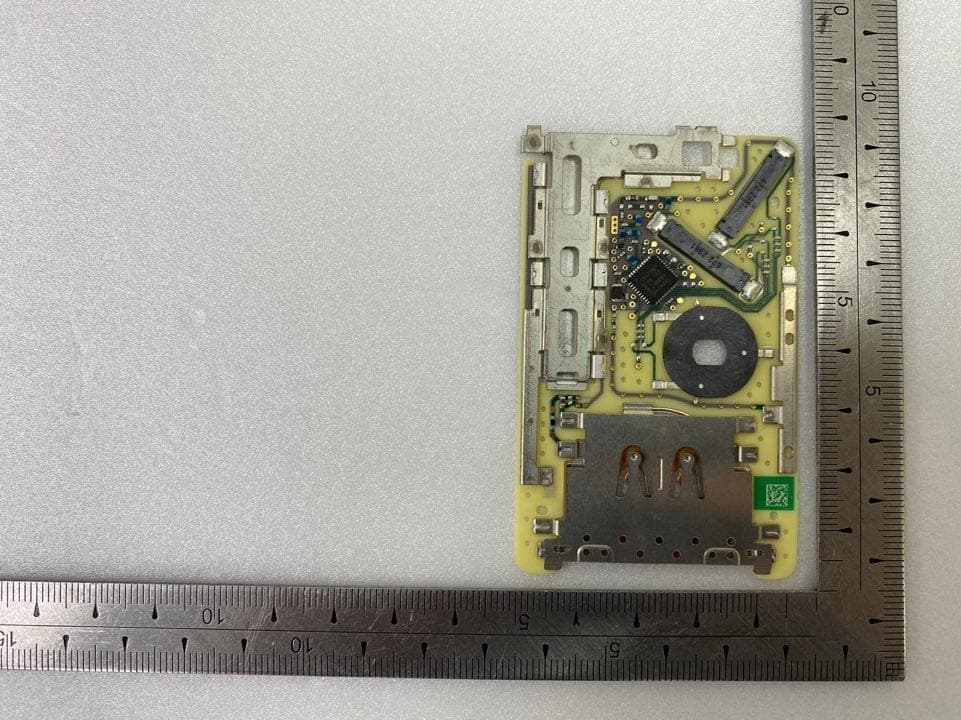
Click to zoom
Application Details
- Equipment Class
- DSC - Part 15 Security/Remote Control Transmitter
- Date of Grant
- Jul 28, 2020
- Application Purpose
- Original Equipment
- Date of Application
- Jul 28, 2020
- Equipment Note
- CARD ASSY ENTRY KEY
- Frequency Range
- 433.66000000 - 434.18000000
- Country
- South Korea
Documents & Files
Document Text
Text extracted from the exhibit documents filed with the FCC. Open a document above to read the original.
Users Manual
CASCO Identification No. : Document : User Manual for TOKEN PLUS Cardkey Project : SVI-HOCFGE00 Project Code : Version: 1.0 Date: Jul. 07. '20 Engineering change order-No.: Design Freeze No.: Number of pages: 6 Filename: Editor : JJ.Yoon Document name Project code Version: 1.0 Jul. 07. 2020 ECO / DF No. Identification No. : Document No. File: Page 2 / 6 Contents list Page 1. System configulation 3 1.1 Scope of SMART KEY SYSTEM 3 1.2 Short description of the SYSTEM 3 1.2.1 General Definition of SMART KEY 3 1.2.2 Wireless Communication 3 1.2.3 Concept Description 3 1.3 System Overview 4 1.4 Smart Card Key Operation 5 2 FCC/IC Compliance Statement 6 Editor : JJ.Yoon Document name Project code Version: 1.0 Jul. 07. 2020 ECO / DF No. Identification No. : Document No. File: Page 3 / 6 1.System configulation 1.1 Scope of SMART KEY SYSTEM The System offers the following features: passive access for two doors, driver side and passenger side as well as trunk/tailgate passive start after interior detection of the SMART Cardkey (without interior trunk and hat shelf detection) LF-RF communication passive access trunk/tailgate via the trunk lid switch at the trunk max. 6 SMART KEY FOB/Cardkey can be handled by the system communication to the engine management system via a single line interface communication to the ESCL via a single line interface 1.2 Short description of the SYSTEM 1.2.1 General Definition of SMART KEY The SMART KEY system is a system that allows the user to access and operate a vehicle in a very convenient way. To access the vehicle no traditional key or remote control unit is needed. The user carries a SMART KEY Cardkey which itself does not require any conscious actions by the user (e.g. operate a button). After being triggered the vehicle sends out a request in a limited range. If the SMART KEY Cardkey receives this request, it automatically sends a response to the vehicle. Then the system decides whether to perform a particular action (unlocking, locking...) or remain inactive. 1.2.2 Wireless Communication Electromagnetic waves are used to exchange information between the vehicle and the SMART KEY Cardkey. Both, vehicle and SMART KEY Cardkey are equipped with a transmitter, a receiver and several antennas. 1.2.3 Concept Description With this concept it is possible to have a set of interior antennas that covers the vehicle’s interior and a set of exterior antennas that covers the vehicle’s exterior. For an unambiguous separation between the vehicle’s interior and exterior it is sufficient that at least one area is covered exactly by the corresponding operating ranges of the antennas. The functions of the SMART KEY system have to be provided in a clearly defined and limited range. For the up-link from the vehicle to the SMART KEY Cardkey, a magnetic field with a frequency of 125 kHz and ASK modulation is used. Inductive antennas in and at the vehicle radiate the electromagnetic energy. Editor : JJ.Yoon Document name Project code Version: 1.0 Jul. 07. 2020 ECO / DF No. Identification No. : Document No. File: Page 4 / 6 Technical aspects of 125 kHz – magnetic field: virtually no reflections, cubical decrease of field strength allows good range control, released frequency band (ISM), high penetration, low quiescent current demand due to 125 kHz input stage (SMART KEY Cardkey), less sensitive for detuning compared to higher frequency. For the down-link from the SMART KEY Cardkey to the vehicle, the standard radio frequency (RF) is used (similar to the classic remote control functions) with FSK modulation. 1.3 System Overview Figure 1: Principle of Communication ECU sends LF challenge via exterior antenna ID tag sends identification code to RF receiver Doors are unlocked automatically User pulls open the door LF R F Editor : JJ.Yoon Document name Project code Version: 1.0 Jul. 07. 2020 ECO / DF No. Identification No. : Document No. File: Page 5 / 6 1.4 Smart Card Key Operation As below photo, this card key doesn’t have keytop on the product. Just put this card key in pocket, and when you go to your car closely, the Smart card key system acknowledge automatically. When you want to change battery, just put it as below. Please be aware battery polarity, else the battery is discharged rapidly. Editor : JJ.Yoon Document name Project code Version: 1.0 Jul. 07. 2020 ECO / DF No. Identification No. : Document No. File: Page 6 / 6 2 FCC/IC Compliance Statement FCC Compliance Statement. This device complies with part 15 of the FCC Rules. Operation is subject to the following two conditions : (1) This device may not cause harmful interference, and (2) This device must accept any interference received, including interferencethat may cause undesired operation. Do Not Any changes or modifications to the equipment not expressly approved by the party responsible for compliance could void user’s authority to operate the equipment. FCC Information to User This equipment has been tested and found to comply with the limits for a Class B digital device, pursuant to Part 15 of the FCC Rules. These limits are designed to provide reasonable protection against harmful interference in a residential installation. This equipment generates, uses and can radiate radio frequency energy and, if not installed and used in accordance with the instructions, may cause harmful interference to radio communications. However, there is no guarantee that interference will not occur in a particular installation. If this equipment does cause harmful interference to radio or television reception, which can be determined by turning the equipment off and on, the user is encouraged to try to correct the interference by one of the following measures: • Reorient or relocate the receiving antenna. • Increase the separation between the equipment and receiver. • Connect the equipment into an outlet on a circuit different from that to which the receiver is con- nected. • Consult the dealer or an experienced radio/TV technicia…
Text truncated - open the document above for the full version.
Cover Letter(s)
<Continental Automotive Systems Corporation> Office of Engineering Technology Federal Communications Commission 7435 Oakland Mills Road Columbia, MD 21046 Date: July 23, 2020 Subject; Request for Confidentiality FCC ID: SY5HOCFGE00 To Whom It May Concern, Pursuant to the provisions of Sections 0.457 and 0.459 of Commission's rules (47CFR0.457, 0.459), we are requesting the Commission to withhold the following attachment(s) as confidential document from public disclosure indefinitely. • Schematic Diagram • Block Diagram • Part List • Operational Description Above mentioned document contains detailed system and equipment description are considered as proprietary information in operation of the equipment. The public disclosure of above documents might be harmful to our company and would give competitor an unfair advantage in the market. In additional to above mentioned documents, pursuant to Public Notice DA 04-1705 of the Commission' s policy, in order to comply with the marketing regulations in 47 CFT §2.803 and the importation rules in 47 CFR §2.1204, while ensuring that business sensitive information remains confidential until the actual marketing of newly authorized devices. We are requesting the commission to grant shot-term confidentiality request on the following attachment(s) for 180 days after the grant as outlined in Public Notice DA 04-1705. • External Photos • Internal Photos • Test Setup Photos • User Manual It is our understanding that all measurement test reports, FCC ID label format and correspondent during certification review process cannot be granted as confidential documents and those information will be available for public review once the grant of equipment authorization is issued. Sincerely, Signature: Name: Sung-Min Jang Title: Representative
ID Label/Location Info
Page 1 of 1 IDENTIFICATION LABEL: PROPOSED FCC ID LABEL The FCC ID shall be permanently affixed in the rear side of the equipment Authorized Person - Print Name: Sung-Min Jang Date: July 23, 2020 Signature: FCC ID : SY5HOCFGE00
Internal Photos
Built-in PCB Antenna
Test Report
Page 1 of 32 Report No.: OT-207-RWD-041 It should not be reproduced except in full, without the written approval of ONETECH. EMC-003 (Rev.2) ONETECH Corp.: 43-14, Jinsaegol-gil, Chowol-eup, Gwangju-si, Gyeonggi-do, 12735, Korea (TEL: 82-31-799-9500, FAX: 82-31-799-9599) RADIO PERFORMANCE TEST REPORT Test Report No. : OT-207-RWD-041 AGR No. : A207A-065 Applicant : Continental Automotive Systems Corporation Address : 45-29, Saeum-ro, Icheon-si, Gyeonggi-Do, South Korea Manufacturer : Continental Automotive Systems Corporation Address : 45-29, Saeum-ro, Icheon-si, Gyeonggi-Do, South Korea Type of Equipment : CARD ASSY ENTRY KEY FCC ID : SY5HOCFGE00 Model No. : SVI-HOCFGE00 Serial number : N/A Total page of Report : 32 pages (including this page) Date of Incoming : July 06, 2020 Date of issuing : July 22, 2020 SUMMARY The equipment complies with the regulation; FCC PART 15 SUBPART C Section 15.209 and Section 15.231 This test report only contains the result of a single test of the sample supplied for the examination. It is not a generally valid assessment of the features of the respective products of the mass-production. Reviewed by: Approved by: Ha-Ram Lee / Manager Ki-Hong, Nam / General Manager ONETECH Corp. ONETECH Corp. Page 2 of 32 Report No.: OT-207-RWD-041 It should not be reproduced except in full, without the written approval of ONETECH. EMC-003 (Rev.2) ONETECH Corp.: 43-14, Jinsaegol-gil, Chowol-eup, Gwangju-si, Gyeonggi-do, 12735, Korea (TEL: 82-31-799-9500, FAX: 82-31-799-9599) CONTENTS ...........................................................................................................................................................................................PAGE 1. VERIFICATION OF COMPLIANCE .............................................................................................................................. 5 2. TEST SUMMARY ............................................................................................................................................................... 6 2.1 TEST ITEMS AND RESULTS .............................................................................................................................................. 6 2.2 ADDITIONS, DEVIATIONS, EXCLUSIONS FROM STANDARDS ............................................................................................ 6 2.3 RELATED SUBMITTAL(S) / GRANT(S) ............................................................................................................................. 6 2.4 PURPOSE OF THE TEST .................................................................................................................................................... 6 2.5 TEST METHODOLOGY ..................................................................................................................................................... 6 2.6 TEST FACILITY ................................................................................................................................................................ 6 3. GENERAL INFORMATION ............................................................................................................................................. 7 3.1 PRODUCT DESCRIPTION .................................................................................................................................................. 7 3.2 ALTERNATIVE TYPE(S)/MODEL(S); ALSO COVERED BY THIS TEST REPORT. ................................................................. 7 4. EUT MODIFICATIONS ..................................................................................................................................................... 8 5. SYSTEM TEST CONFIGURATION ................................................................................................................................ 8 5.1 JUSTIFICATION ................................................................................................................................................................ 8 5.2 PERIPHERAL EQUIPMENT ............................................................................................................................................... 8 5.3 MODE OF OPERATION DURING THE TEST ....................................................................................................................... 8 5.4 CONFIGURATION OF TEST SYSTEM .............................................................................................................................. 11 5.5 ANTENNA REQUIREMENT ............................................................................................................................................. 11 6. PRELIMINARY TEST ..................................................................................................................................................... 12 6.1 AC POWER LINE CONDUCTED EMISSIONS TESTS ........................................................................................................ 12 6.2 GENERAL RADIATED EMISSIONS TESTS ...................................................................................................................... 12 7. BANDWIDTH MEASUREMENT ................................................................................................................................... 13 7.1 OPERATING ENVIRONMENT .......................................................................................................................................... 13 7.2 TEST SET-UP .................................................................................................................................................................. 13 7.3 TEST EQUIPMENT USED ................................................................................................................................................. 13 7.4 TEST DATA .......................................................................................................…
Text truncated - open the document above for the full version.
Test Setup Photos
Page 1 of 3 - Radiated Emission Test (Below 30 MHz) Page 2 of 3 - Radiated Emission Test (30 MHz ~ 1 GHz) Page 3 of 3 - Radiated Emission Test (Above 1 GHz)
Contact Information
Applicant
Sung-Min Jang(Representative)
Technical Contact
Test Firm
ONETECH Corp.Ki Hong Nam
Technical Specifications
| # | Rule Parts | Frequency Range | Power Output |
|---|---|---|---|
| 1 | 15.231 | 433.66 MHz - 434.18 MHz | - |
Other Applications from Continental Automotive Korea Ltd.
SY5SLAVE
Jun 03, 2026UNIT.ASSY-UWB&BLE
Equipment Class
UWB - Ultra Wideband TransmitterSY5UWB
Jun 02, 2026UNIT.ASSY-UWB
Equipment Class
UWB - Ultra Wideband TransmitterSY5MASTER
Jun 02, 2026UNIT.ASSY-UWB&BLE
Equipment Class
UWB - Ultra Wideband Transmitter
SY5KA4FGE09
May 07, 2021Smart Key Fob
Equipment Class
DSC - Part 15 Security/Remote Control Transmitter
SY5IBU21N
Nov 30, 2020IBU(Integrated Body Control Unit)
Equipment Class
DCD - Part 15 Low Power Transmitter Below 1705 kHz