SY5KA4FGE07Smart Key Fob
Continental Automotive Korea Ltd.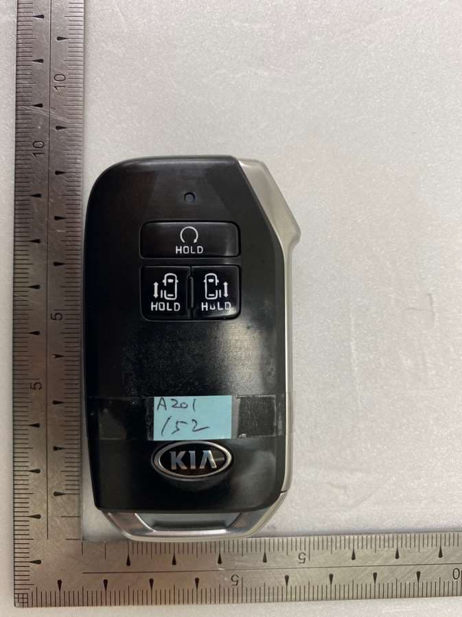
Click to zoom
Application Details
- Equipment Class
- DSC - Part 15 Security/Remote Control Transmitter
- Date of Grant
- Mar 08, 2020
- Application Purpose
- Original Equipment
- Date of Application
- Mar 08, 2020
- Equipment Note
- Smart Key Fob
- Frequency Range
- 433.92000000 - 433.92000000
- Country
- South Korea
Documents & Files
Document Text
Text extracted from the exhibit documents filed with the FCC. Open a document above to read the original.
Users Manual
CASCO Identification No. : Document : User Manual for TOKEN/TOKEN PLUS Fob Model : SVI-KA4FGE07 Project Code : Version: 1.0 Date: Sep. 20. '19 Engineering change order-No.: Design Freeze No.: Number of pages: 6 Filename: Editor : KS.Kim Document name Project code Version: 1.0 Sep. 20. 2019 ECO / DF No. Identification No. : Document No. File: Page 2 / 6 Contents list Page 1. System configulation 3 1.1 Scope of SMART KEY SYSTEM 3 1.2 Short description of the SYSTEM 3 1.2.1 General Definition of SMART KEY 3 1.2.2 Wireless Communication 3 1.2.3 Concept Description 3 1.3 System Overview / Block Diagram 4 1.4 Smart Key Fob button operation 5 2 FCC/IC Compliance Statement 6 Editor : KS.Kim Document name Project code Version: 1.0 Sep. 20. 2019 ECO / DF No. Identification No. : Document No. File: Page 3 / 6 1.System configulation 1.1 Scope of SMART KEY SYSTEM The System offers the following features: passive access for two doors, driver side and passenger side as well as trunk/tailgate passive start after interior detection of the SMART KEY FOB (without interior trunk and hat shelf detection) LF-RF communication passive access trunk/tailgate via the trunk lid switch at the trunk max. 4 SMART KEY FOBs can be handled by the system communication to the engine management system via a single line interface communication to the ESCL via a single line interface 1.2 Short description of the SYSTEM 1.2.1 General Definition of SMART KEY The SMART KEY system is a system that allows the user to access and operate a vehicle in a very convenient way. To access the vehicle no traditional key or remote control unit is needed. The user carries a SMART KEY FOB which itself does not require any conscious actions by the user (e.g. operate a button). After being triggered the vehicle sends out a request in a limited range. If the SMART KEY FOB receives this request, it automatically sends a response to the vehicle. Then the system decides whether to perform a particular action (unlocking, locking...) or remain inactive. 1.2.2 Wireless Communication Electromagnetic waves are used to exchange information between the vehicle and the SMART KEY FOB. Both, vehicle and SMART KEY FOB are equipped with a transmitter, a receiver and several antennas. 1.2.3 Concept Description With this concept it is possible to have a set of interior antennas that covers the vehicle’s interior and a set of exterior antennas that covers the vehicle’s exterior. For an unambiguous separation between the vehicle’s interior and exterior it is sufficient that at least one area is covered exactly by the corresponding operating ranges of the antennas. The functions of the SMART KEY system have to be provided in a clearly defined and limited range. For the up-link from the vehicle to the SMART KEY FOB, a magnetic field with a frequency of 125 kHz and ASK modulation is used. Inductive antennas in and at the vehicle radiate the electromagnetic energy. Editor : KS.Kim Document name Project code Version: 1.0 Sep. 20. 2019 ECO / DF No. Identification No. : Document No. File: Page 4 / 6 Technical aspects of 125 kHz – magnetic field: virtually no reflections, cubical decrease of field strength allows good range control, released frequency band (ISM), high penetration, low quiescent current demand due to 125 kHz input stage (SMART KEY FOB), less sensitive for detuning compared to higher frequency. For the down-link from the SMART KEY FOB to the vehicle, the standard radio frequency (RF) is used (similar to the classic remote control functions) with FSK modulation. 1.3 System Overview / Block Diagram Figure 1: Principle of Communication ECU sends LF challenge via exterior antenna ID tag sends identification code to RF receiver Doors are unlocked automatically User pulls open the door L F R F Editor : KS.Kim Document name Project code Version: 1.0 Sep. 20. 2019 ECO / DF No. Identification No. : Document No. File: Page 5 / 6 1.4 Smart Key Fob button operation Lock Remote Start Door open/close (Left button) Unlock ; Driver’s rear side door Door open/close (Right button) Hold (Trunk) ; Passenger’s rear side door Panic You can lock, unlock, open trunk and so on your vehicle with this remote transmitter. Lock - When you push this button, all the doors will be locked. - You can not lock any of the doors with this remote transmitter if any door is open or the key is in the fob holder. Unlock - When you push this button, all the doors will be unlocked. - You can not unlock any of the doors with this remote transmitter if any door is open or the key is in the fob holder. HOLD(Trunk) - When you push this button and hold more than 1 second, the trunk will be opened. Remote Start - When you push and hold this button for about 3 second, vechicle will be started. Door open/close (Left button) - When you push and hold this button for about 1 second, - Driver’s rear side door will be opened/closed. Door open/close (Right button) - When you push and hold this button for about 1 second, - Passenger’s rear side door will be opened/closed. Panic - When you push this button for about 1 second, Horn will alarm. Editor : KS.Kim Document name Project code Version: 1.0 Sep. 20. 2019 ECO / DF No. Identification No. : Document No. File: Page 6 / 6 2 FCC/IC Compliance Statement FCC Compliance Statement. This device complies with part 15 of the FCC Rules. Operation is subject to the following two conditions : (1) This device may not cause harmful interference, and (2) This device must accept any interference received, including interferencethat may cause undesired operation. Do Not Any changes or modifications to the equipment not expressly approved by the party responsible for compliance could void user’s authority to operate the equipment. IC Compliance Statement. Le present appareil est conforme aux CNR d’Industrie Canada applicables aux appareils radio exempts de licence. L’exploitation est autorisee aux deux conditions suivantes : (1) l’appareil ne doit pas produire de b…
Text truncated - open the document above for the full version.
Cover Letter(s)
SCS-F18: Project and Product Certification Representative Authorization Letter Page 1 of 2 Rev 6.0 775 Montague Expressway Milpitas, CA 95035 Tel: 408-526-1188 Fax: 408-526-1088 Email: [email protected] Project and Product Certification Representative Authorization Letter Reason for Amendment (current / obsolete) Revision History Approved Date From To Initial Release (obsolete) 1.0 1.0 Nov-14-2006 Revised wording (obsolete) 1.0 2.0 Sept–25-2007 Updated company template (obsolete) 2.0 3.0 Jan-31-2012 Updated letter information (obsolete) 3.0 4.0 May-23-2014 Added FCC ID field (obsolete) 4.0 5.0 Sep-16-2014 Updated company name & logo (current) 5.0 6.0 Jun-27-2018 SCS-F18: Project and Product Certification Representative Authorization Letter Page 2 of 2 Rev 6.0 Continental Automotive Systems Corporation (March 02, 2020) To: BVCPS, INC. 775 Montague Expressway, Milpitas, CA 95035 USA Dear Sir/Madam, Re: Product Certification Representative Authorization Letter We, _____ Continental Automotive Systems Corporation _____ hereby authorize Bureau Veritas Consumer Product Services, Inc. to act as a Certification Body for certifying for the following project(s): FCC ID: SY5KA4FGE07 Product Description: Smart Key Fob Model: SVI-KA4FGE07 Sincerely, ______________________________ Client’s signature Client’s name / title : Sung-Min Jang / Representative Contact information / address : 45-29, Saeum-ro, Icheon-si, Gyeonggi-do, 467-080, Korea Telephone: 82-31-645-4864 Fax No.: 82-31-637-0371 E-mail: [email protected]
Cover Letter(s)
SCS-F19: Confidentiality Request Letter Page 1 of 3 Rev 6.0 775 Montague Expressway Milpitas, CA 95035 Tel: 408-526-1188 Fax: 408-526-1088 Email: [email protected] Confidentiality Request Letter Reason for Amendment (current / obsolete) Revision History Approved Date From To Initial Release (obsolete) 1.0 1.0 Nov-14-2006 Adding CFR 2.459 (obsolete) 1.0 2.0 August – 11 - 2008 Updated company template & Added text box (obsolete) 2.0 3.0 Jan-31-2012 Added IC confidentiality letter form (obsolete) 3.0 4.0 March-26-2015 Corrections to STC form. Added reference to KDB (obsolete) 4.0 5.0 Nov-19-2015 Updated company logo (current) 5.0 6.0 Jun-26-2019 SCS-F19: Confidentiality Request Letter Page 2 of 3 Rev 6.0 Continental Automotive Systems Corporation (March 02, 2020) To: Federal Communications Commission Authorization and Evaluation Division 7435 Oakland Mills Road Columbia, MD Subject: Permanent Confidentiality Request for FCC ID: SY5KA4FGE07 Pursuant to sections 0.457 and 0.459 of CFR 47, we respectfully request permanent confidential treatment of the following Exhibits accompanying this application as: Block Diagram Schematics Operational Description The above materials contain trade secrets and proprietary information not customarily released to the public. The public disclosure of these materials may be harmful to the applicant and provide unjustified benefits to its competitors. The applicant understands that disclosure of this application and all accompanying documentation will not be made before the date of the Grant for this application. Sincerely, ______________________________ Client’s signature Client’s name / title : Sung-Min Jang / Representative Contact information / address : 45-29, Saeum-ro, Icheon-si, Gyeonggi-do, 467-080, Korea Telephone: 82-31-645-4864 Fax No.: 82-31-637-0371 E-mail: [email protected] SCS-F19: Confidentiality Request Letter Page 3 of 3 Rev 6.0 Continental Automotive Systems Corporation (March 02, 2020) To: Federal Communications Commission Office of Engineering and Technology Equipment Authorization Division 7345 Oakland Mills Road Columbia, Maryland 21046 Subject: Short Term Confidentiality Request for FCC ID: SY5KA4FGE07 To Whom It May Concern: Pursuant to sections 0.457 and 0.459 of CFR 47, and to avoid premature release of sensitive information prior to marketing or release of the product to the public, the applicant requests the following documents contained in this certification application be temporarily withheld from public disclosure for an initial period of 45 or 180 days; or for a specified date of / / not to exceed 180 days from the Grant Date. See KDB 726920. User Manual Internal Photos Test Setup photos External Photos The above materials contain trade secrets and proprietary information not customarily released to the public. The public disclosure of these materials may be harmful to the applicant and provide unjustified benefits to its competitors. Sincerely, ______________________________ Client’s signature Client’s name / title : Sung-Min Jang / Representative Contact information / address : 45-29, Saeum-ro, Icheon-si, Gyeonggi-do, 467-080, Korea Telephone: 82-31-645-4864 Fax No.: 82-31-637-0371 E-mail: [email protected]
ID Label/Location Info
FCC ID LABEL LOCATION 1. FCC ID label drawing 2. FCC ID label location SVI-KA4FGE07 FCC ID: SY5KA4FGE07 Made in Korea
Test Report
Page 1 of 23 Report No.: OT-203-RWD-012 It should not be reproduced except in full, without the written approval of ONETECH. EMC-003 (Rev.2) ONETECH Corp.: 43-14, Jinsaegol-gil, Chowol-eup, Gwangju-si, Gyeonggi-do, 12735, Korea (TEL: 82-31-799-9500, FAX: 82-31-799-9599) RADIO PERFORMANCE TEST REPORT Test Report No. : OT-203-RWD-012 AGR No. : A201A-152 Applicant : Continental Automotive Systems Corporation Address : 45-29, Saeum-ro, Icheon-City, Gyeonggi-Do, Korea Manufacturer : Continental Automotive Systems Corporation Address : 45-29, Saeum-ro, Icheon-City, Gyeonggi-Do, Korea Type of Equipment : Smart Key Fob FCC ID : SY5KA4FGE07 Model No. : SVI-KA4FGE07 Serial number : N/A Total page of Report : 23 pages (including this page) Date of Incoming : January 31, 2020 Date of issuing : March 02, 2020 SUMMARY The equipment complies with the regulation; FCC PART 15 SUBPART C Section 15.209 and Section 15.231 This test report only contains the result of a single test of the sample supplied for the examination. It is not a generally valid assessment of the features of the respective products of the mass-production. Reviewed by: Approved by: Ha-Ram Lee / Assistant Manager Jae-Ho Lee / Chief Engineer ONETECH Corp. ONETECH Corp. Page 2 of 23 Report No.: OT-203-RWD-012 It should not be reproduced except in full, without the written approval of ONETECH. EMC-003 (Rev.2) ONETECH Corp.: 43-14, Jinsaegol-gil, Chowol-eup, Gwangju-si, Gyeonggi-do, 12735, Korea (TEL: 82-31-799-9500, FAX: 82-31-799-9599) CONTENTS ...........................................................................................................................................................................................PAGE 1. VERIFICATION OF COMPLIANCE .............................................................................................................................. 5 2. TEST SUMMARY ............................................................................................................................................................... 6 2.1 TEST ITEMS AND RESULTS .............................................................................................................................................. 6 2.2 ADDITIONS, DEVIATIONS, EXCLUSIONS FROM STANDARDS ............................................................................................ 6 2.3 RELATED SUBMITTAL(S) / GRANT(S) ............................................................................................................................. 6 2.4 PURPOSE OF THE TEST .................................................................................................................................................... 6 2.5 TEST METHODOLOGY ..................................................................................................................................................... 6 2.6 TEST FACILITY ................................................................................................................................................................ 6 3. GENERAL INFORMATION ............................................................................................................................................. 7 3.1 PRODUCT DESCRIPTION .................................................................................................................................................. 7 3.2 ALTERNATIVE TYPE(S)/MODEL(S); ALSO COVERED BY THIS TEST REPORT. ................................................................. 7 4. EUT MODIFICATIONS ..................................................................................................................................................... 8 5. SYSTEM TEST CONFIGURATION ................................................................................................................................ 8 5.1 JUSTIFICATION ................................................................................................................................................................ 8 5.2 PERIPHERAL EQUIPMENT ............................................................................................................................................... 8 5.3 MODE OF OPERATION DURING THE TEST ....................................................................................................................... 8 5.4 CONFIGURATION OF TEST SYSTEM .............................................................................................................................. 10 5.5 ANTENNA REQUIREMENT ............................................................................................................................................. 10 6. PRELIMINARY TEST ..................................................................................................................................................... 11 6.1 AC POWER LINE CONDUCTED EMISSIONS TESTS ........................................................................................................ 11 6.2 GENERAL RADIATED EMISSIONS TESTS ...................................................................................................................... 11 7. BANDWIDTH MEASUREMENT ................................................................................................................................... 12 7.1 OPERATING ENVIRONMENT .......................................................................................................................................... 12 7.2 TEST SET-UP .................................................................................................................................................................. 12 7.3 TEST EQUIPMENT USED ................................................................................................................................................. 12 7.4 TEST DATA ..........................................................................................................…
Text truncated - open the document above for the full version.
Test Setup Photos
Page 1 of 3 - Radiated Emission Test (Below 30 MHz) Page 2 of 3 - Radiated Emission Test (Below 1 GHz) Page 3 of 3 - Radiated Emission Test (Above 1 GHz)
Contact Information
Applicant
Sung-Min Jang(Representative)
Test Firm
ONETECH Corp.Ki Hong Nam
Technical Specifications
| # | Rule Parts | Frequency Range | Power Output |
|---|---|---|---|
| 1 | 15.231 | 433.92 MHz - 433.92 MHz | - |
Other Applications from Continental Automotive Korea Ltd.
SY5SLAVE
Jun 03, 2026UNIT.ASSY-UWB&BLE
Equipment Class
UWB - Ultra Wideband TransmitterSY5UWB
Jun 02, 2026UNIT.ASSY-UWB
Equipment Class
UWB - Ultra Wideband TransmitterSY5MASTER
Jun 02, 2026UNIT.ASSY-UWB&BLE
Equipment Class
UWB - Ultra Wideband Transmitter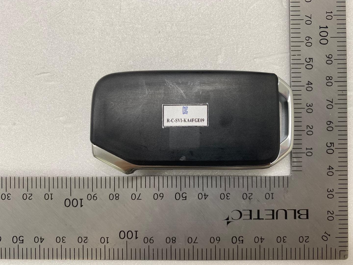
SY5KA4FGE09
May 07, 2021Smart Key Fob
Equipment Class
DSC - Part 15 Security/Remote Control Transmitter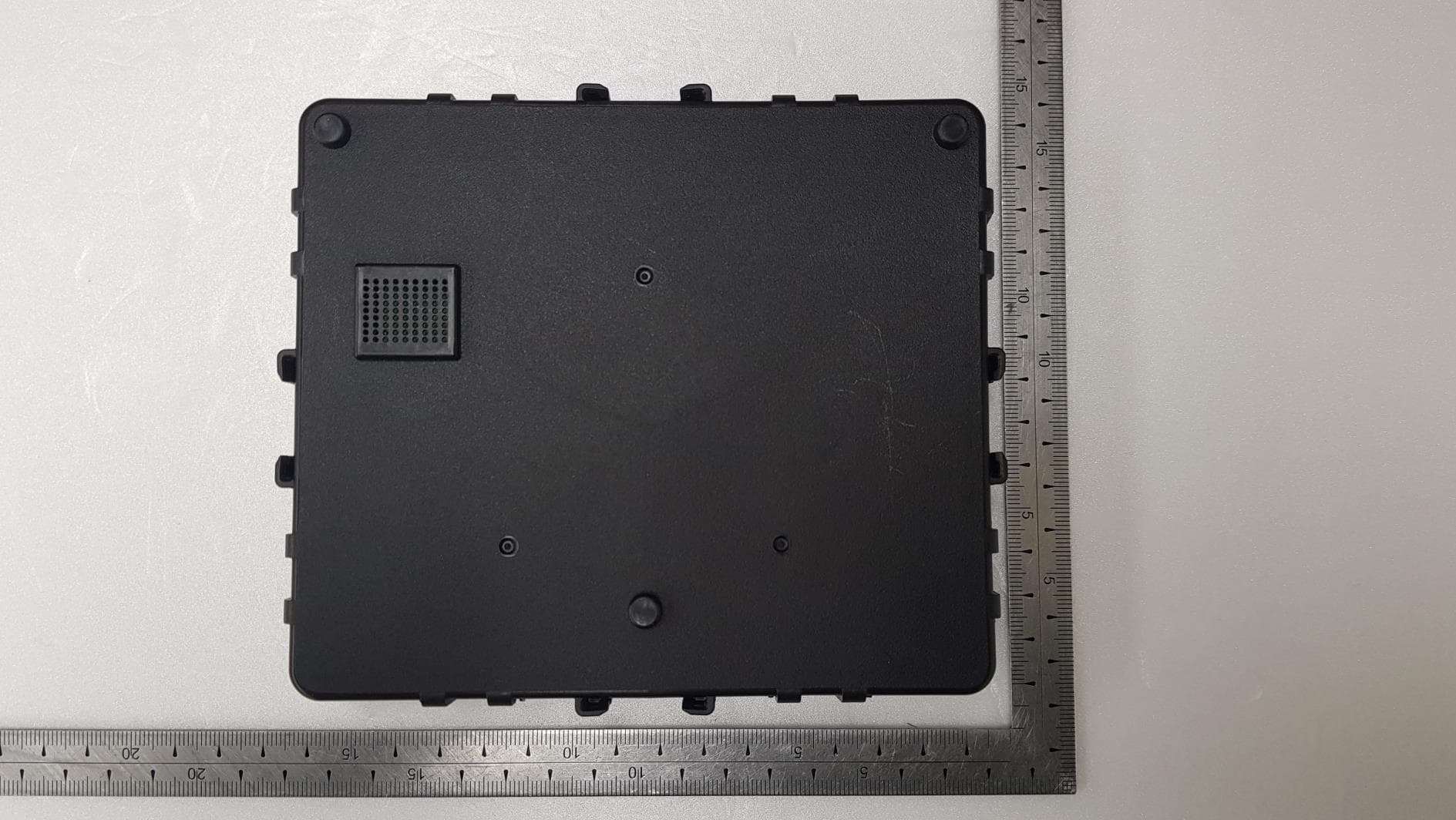
SY5IBU21N
Nov 30, 2020IBU(Integrated Body Control Unit)
Equipment Class
DCD - Part 15 Low Power Transmitter Below 1705 kHz