SYA78713Ear tag reader for livestock
ID-ology DBA Remote Ag Data, Inc.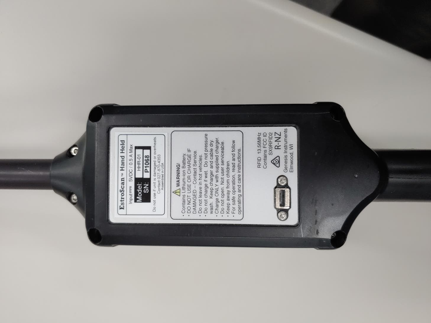
Click to zoom
Application Details
- Equipment Class
- DXX - Part 15 Low Power Communication Device Transmitter
- Date of Grant
- Jul 20, 2020
- Application Purpose
- Original Equipment
- Date of Application
- Jul 20, 2020
- Equipment Note
- Ear tag reader for livestock
- Frequency Range
- 13.56000000 - 13.56000000
- Country
- United States
Documents & Files
Document Text
Text extracted from the exhibit documents filed with the FCC. Open a document above to read the original.
Attestation Statements
Test Lab Attestation Letter Date of Test: March 4 thru April 2, 2020 Applicant Name: I.D.ology FCC ID: SYA78713 Test Item: Ear Tag Reader Model: EstroScan II Name of Engineer Performing Test: Joseph Strzelecki, Richard Tichgelaar, Dave Jarvis Radiometrics Midwest Corporation Statement of Compliance: Radiometrics declares that this Unit has been tested in accordance with the test method identified in this test report and that we observed it being tested. We also declare that the Unit complies with the relevant limits. All instrumentation and accessories used to test this unit for compliance to the indicated test method are calibrated regularly in accordance with ISO 17025:2005 requirements by laboratories accredited by A2LA, NVLAP, or ACLAS for the measurement parameters. The measurements were made at: Radiometrics Midwest Corporation 12 Devonwood Avenue Romeoville IL 60446 Test Lab Witness- Joseph Strzelecki Signature of Test Lab Witness: 07/09/2020 Full Name, Typed: Joseph R Strzelecki Title of Witness: Senior EMC Engineer Email Address: [email protected] Phone No.: 815-293-0772 Test Lab Stamp:
Cover Letter(s)
Page 1 of 1 RP-9254AL 12 E Devonwood Ave SOL VING A WAV E OF EMI COMP LIANCE PR OB LE MS Romeoville, IL 60446 Tel: (815) 293-0772 Federal Communications Commission July 13, 2020 Authorization and Evaluation Division 7435 Oakland Mills Rd. Columbia, MD 21046 Reference FCC ID: SYA78713 Organization: I.D.ology 1. Long Term Confidentiality Pursuant to Sections 0.457 and 0.459 of the Commission’s Rules, I.D.ology hereby requests long-term confidential treatment of information accompanying this application as outlined below: Exhibit Type File Name Circuit Schematics 7a ID-Ology RFID Reader Board Schematics 9254 7b ID-Ology DLP Board Schematics 9254 Block Diagram 8 ID-Ology Block Diagram 9254 EUT description (Operational Description) 10 ID-Ology EUT Description 9254 The above materials contain trade secrets and proprietary information not customarily released to the public. The public disclosure of these materials may be harmful to the applicant and provide unjustified benefits to its competitors. The applicant understands that pursuant to Section 0.457 of the Rules, disclosure of this application and all accompanying documentation will not be made before the date of the Grant for this application. Pursuant to DA04-1705 June 15, 2004 of the Commission’s public notice, we also request temporary confidential treatment of information accompanying this application as outlined below: Exhibit Type File Name Internal Photos 4 ID-Ology Internal Photos 9254 Please hold confidential for 180 days Authorized Signature Joseph Strzelecki Senior EMC Engineer Radiometrics Midwest Corporation Authorized Agent for I.D.ology
External Photos
Authorized Agent: Radiometrics Midwest Corporation (815) 293-0772 External EUT Photographs Front of Tag Reader Back of Tag Reader Authorized Agent: Radiometrics Midwest Corporation (815) 293-0772 Front of Hand-Held Back of Hand-Held Authorized Agent: Radiometrics Midwest Corporation (815) 293-0772 Full RFID reader
ID Label/Location Info
Authorized Agent: Radiometrics Midwest Corporation (815) 293-0772 ID Label/Location Drawing of label The actual size of the label is 1.25 x 3.5 inches. The Label will be made of mylar, using 3M permanent adhesive Radiometrics Midwest Corporation (815) 293-0772 – [email protected] Drawing/Photograph showing placement of Label Location: The label will be on the back of the handle, as shown by the red box:
Internal Photos
Authorized Agent: Radiometrics Midwest Corporation (815) 293-0772 Internal EUT Photographs Top of Main PCB Authorized Agent: Radiometrics Midwest Corporation (815) 293-0772 Bottom of Main PCB Top of HF PCB Authorized Agent: Radiometrics Midwest Corporation (815) 293-0772 Bottom of HF PCB HF PCB installed Authorized Agent: Radiometrics Midwest Corporation (815) 293-0772 Main PCB installed Daughter board Daughter board Authorized Agent: Radiometrics Midwest Corporation (815) 293-0772 Battery located in handle 13.56 MHz Antenna Authorized Agent: Radiometrics Midwest Corporation (815) 293-0772 134 kHz Antenna Authorized Agent: Radiometrics Midwest Corporation (815) 293-0772 Antennas installed
RF Exposure Info
Authorized Agent: Radiometrics Midwest Corporation www.radiomet.com RF Exposure FCC ID: SYA78713 1.0 INTRODUCTION These calculations are based on the highest EIRP possible from the EUT considering maximum conducted power and antenna gain or EIRP from a radiated emissions test. Although the duty cycle is less than 100%, for all calculations, 100% will be used as a worst-case. 2.0 FCC RF EXPOSURE COMPLIANCE RESULT: In accordance with FCC KDB Publication 447498 D01 V06 Clause 4.3.1 c) for transmit frequencies below 100 MHz: 1) For test separation distances >50 mm and <200 mm, the power threshold at the corresponding test separation distance at 100 MHz in section 4.3.1 step b) is multiplied by [1 + log(100/f(MHz))] 2) For test separation distances ≤ 50 mm, the power threshold determined by the equation in c) 1) for 50 mm and 100 MHz is multiplied by ½ This table is for devices with a separation less than 50 mm MHz Max Power dBm Duty Cycle % EUT EIRP mW Min Sep mm SAR Exc Threshold at 50mm 4.3.1 a) in mW SAR Exclusion threshold per 4.3.1 b)1) in mW SAR Exclusion threshold per 4.3.1 c) 1) in mWResultNotes 13.56-19.5100.00.011250474.3474.3885.9ExemptPeak 0.1348.1100.06.412150474.3474.31837.1ExemptPeak EUT EIRP << SAR exclusion threshold per 4.3.1 c) 2) It was measured to be 103.3 dBuV/m at 125 kHz at 3 meters or 8.1 dBm or 6.4 mW EIRP. It was measured to be 75.7 dBuV/m at 13.56 MHz at 3 meters or -19.5 dBm or 0.011mW EIRP. 3.0 FCC SAR TESTING EXCLUSION: In accordance with FCC KDB Publication 447498 D01 V05R02 Clause 4.3.1(a), For 100 MHz to 6 GHz and test separation distances ≤ 50 mm, the 1-g and 10-g SAR test exclusion thresholds are determined by the following: [(max. power of channel, including tune-up tolerance, mW) / (min. test separation distance, mm)]x[√f(GHz)] ≤ 3.0 for 1-g SAR, and ≤ 7.5 for 10-g extremity SAR,30 where • f(GHz) is the RF channel transmit frequency in GHz • Power and distance are rounded to the nearest mW and mm before calculation31 • The result is rounded to one decimal place for comparison • The values 3.0 and 7.5 are referred to as numeric thresholds The test exclusions are applicable only when the minimum test separation distance is ≤ 50 mm, and for transmission frequencies between 100 MHz and 6 GHz. When the minimum test separation distance is < 5 mm, a distance of 5 mm according to 4.1 f) is applied to determine SAR test exclusion. This table is for devices with a separation less than 5 mm Authorized Agent: Radiometrics Midwest Corporation www.radiomet.com MHz Max Power dBm Duty Cycle % Average Power mW Min Sep mm SAR Exc Threshold at 5mm 4.3.1 a) SAR Exclusion threshold per 4.3.1 a) for 1-gResultNotes 24412.30100.01.7050.533.0Exempt Judgement: The product is exempt from SAR testing 4.0 MPE CALCULATION FROM FCC 1.1310 Freq. (MHz) Max Power (dBm) Max Power (mW) Max Ant Gain (dBi) Max Ant Gain above Isotropic (numeric) Duty Cycle % Max EIRP (mW) Power Density at ## cm (mW/cm^2) (S) GP Limit (mW/cm^2) MPE Ratio 13.56-19.500.0101.00100.00.010.00000.2000.0000 0.1348.106.4601.00100.06.460.00130.2000.0064 24413.902.451.631.46100.03.570.28431.0000.2843 Total0.2908 ## = 20 cm for 13.56 MHz and 134 kHz ## = 1 cm for 2441 MHz since the BT module is in the handle The maximum conducted power at 2441 MHz is 1.698 mW with a 1.63 dBi gain for an EIRP of 2.47 mW Notes on the above table: In accordance with OET 65, 97-01, Power Density is calculated by S = P*G/(4*π*R^2) Where S = power density (mW/cm2) P = power input to the antenna (mW) G = power gain of the antenna in the direction of interest relative to an isotropic radiator R = distance to the center of radiation of the antenna (cm) Since the calculated power density is less than the limit, this product fully meets the requirements for the general population.
Test Report
Radiomet.com Page 1 of 17 Electromagnetic Compatibility Test Report Tests Performed on an I.D.ology, Inc. Ear Tag/Badge RFID Reader, Model: EstroScan II Radiometrics Document RP-9254 Product Detail: FCC ID: SYA78713 IC: 5678A-20041 Equipment type: 13.56 MHz Frequency Card Reader Test Standards: US CFR Title 47, Chapter I, FCC Part 15 Subpart C FCC Part 15 CFR Title 47: 2020 Canada ISED; RSS-210, Issue 10: 2019 as required for Category I Equipment FCC Part 15.225 Tests Performed For: Test Facility: I.D.ology, Inc. 1324 W. Clairemont Av. Eau Claire, WI 54701 Radiometrics Midwest Corporation 12 Devonwood Avenue Romeoville, IL 60446 Test completion Date(s): April 2, 2020 Document RP-9254 Revisions: Rev. Issue Date Revised By 0 July 16, 2020 1 July 20, 2020 Joseph Strzelecki Radiometrics Midwest Corporation Testing of the I.D.ology, EstroScan II, Ear Tag/Badge RFID Reader RP-9254 Rev. 1 Page 2 of 17 Table of Contents 1.0 ADMINISTRATIVE DATA................................................................................................................. 3 2.0 TEST SUMMARY AND RESULTS ................................................................................................... 3 2.1 RF Exposure Compliance Requirements ...................................................................................... 3 3.0 EQUIPMENT UNDER TEST (EUT) DETAILS .................................................................................. 3 3.1 EUT Description ........................................................................................................................... 3 3.1.1 FCC Section 15.203 & RSS-GEN Antenna Requirements ..................................................... 4 3.2 Related Submittals ....................................................................................................................... 4 4.0 TESTED SYSTEM DETAILS ........................................................................................................... 4 4.1 Tested System Configuration ........................................................................................................ 4 4.2 Special Accessories ..................................................................................................................... 4 4.3 Equipment Modifications ............................................................................................................... 4 5.0 TEST SPECIFICATIONS ................................................................................................................. 4 6.0 TEST PROCEDURE DOCUMENTS ................................................................................................ 4 7.0 RADIOMETRICS’ TEST FACILITIES ............................................................................................... 5 8.0 DEVIATIONS AND EXCLUSIONS FROM THE TEST SPECIFICATIONS ....................................... 5 9.0 CERTIFICATION ............................................................................................................................. 5 10.0 TEST EQUIPMENT TABLE ........................................................................................................... 6 11.0 TEST SECTIONS........................................................................................................................... 6 11.1 AC Conducted Emissions ........................................................................................................... 6 11.2 Radiated RF Emissions .............................................................................................................. 9 11.2.1 Field Strength Calculation .................................................................................................. 10 11.2.2 Radiated Emissions Test Results ....................................................................................... 10 11.3 Magnetic Field Measurements and Decay Factor Calculations ................................................. 13 11.3.1 Magnetic Field Radiated Emissions Results (0.009 to 30 MHz) .......................................... 13 11.4 Occupied Bandwidth Data ........................................................................................................ 14 11.5 Frequency Stability ................................................................................................................... 16 11.5.1 Test Results for Frequency Stability ................................................................................... 16 12.0 MEASUREMENT INSTRUMENTATION UNCERTAINTY ............................................................ 16 13.0 REVISION HISTORY ................................................................................................................... 17 Notice: This report must not be reproduced (except in full) without the written approval of Radiometrics Midwest Corporation. Radiometrics Midwest Corporation Testing of the I.D.ology, EstroScan II, Ear Tag/Badge RFID Reader RP-9254 Rev. 1 Page 3 of 17 1.0 ADMINISTRATIVE DATA Equipment Under Test: An I.D.ology, Inc., Hand-Held Ear Tag/Badge RFID Reader Model: EstroScan II This will be referred to as the EUT in this Report Date EUT Received at Radiometrics: Test Date(s): March 4, 2020 March 4 to April 2, 2020 Test Report Written and Authorized by: Radiometrics’ Personnel Responsible for Test: 07/16/2020 Joseph Strzelecki Senior EMC Engineer NARTE EMC-000877-NE Joseph Strzelecki Senior EMC Engineer Chris E. D’Alessio EMC Technician Test Witnessed By: The tests were not witnessed by personnel from I.D.ology, Inc. 2.0 TEST SUMMARY AND RESULTS The EUT (Equipment Under Test) is a Hand-Held Ear Tag/Badge Reader, model EstroScan II, manufactured by I.D.ology, Inc. The detailed test results are presented in a separate section. The following is a summary of the test results. Emissions Tests Results per RSS-210 & FCC Part 15 Environmental Phenomena Frequency Range Test Result RF Radiated Emissions 30-1000 MHz Pass Co…
Text truncated - open the document above for the full version.
Test Setup Photos
Authorized Agent: Radiometrics Midwest Corporation (815) 293-0772 Test Setup Photographs Photographs of Radiated Emissions Test Setup Authorized Agent: Radiometrics Midwest Corporation (815) 293-0772 Authorized Agent: Radiometrics Midwest Corporation (815) 293-0772 The EUT was tested both Charging and in battery powered modes. Authorized Agent: Radiometrics Midwest Corporation (815) 293-0772 Photograph of Conducted Emissions Test Setup Photograph of OBW Test Authorized Agent: Radiometrics Midwest Corporation (815) 293-0772 Photograph of Frequency Stability Test Setup
Contact Information
Applicant
Robert Kleemeier(President)
Test Firm
Radiometrics Midwest Corp.Joseph Strzelecki
Technical Specifications
| # | Rule Parts | Frequency Range | Power Output |
|---|---|---|---|
| 2 | 15C | 13.56 MHz - 13.56 MHz | - |
Other Applications from ID-ology DBA Remote Ag Data, Inc.
SYAICR04
Mar 07, 2005Hand-held RFID reader for ISO tags with Bluetooth
Equipment Class
DXX - Part 15 Low Power Communication Device Transmitter