SYXRFVI-IIVUI-II
BMI Technologies Inc.
Click to zoom
Application Details
- Equipment Class
- DXT - Part 15 Low Power Transceiver, Rx Verified
- Date of Grant
- Mar 10, 2013
- Application Purpose
- Original Equipment
- Date of Application
- Mar 10, 2013
- Equipment Note
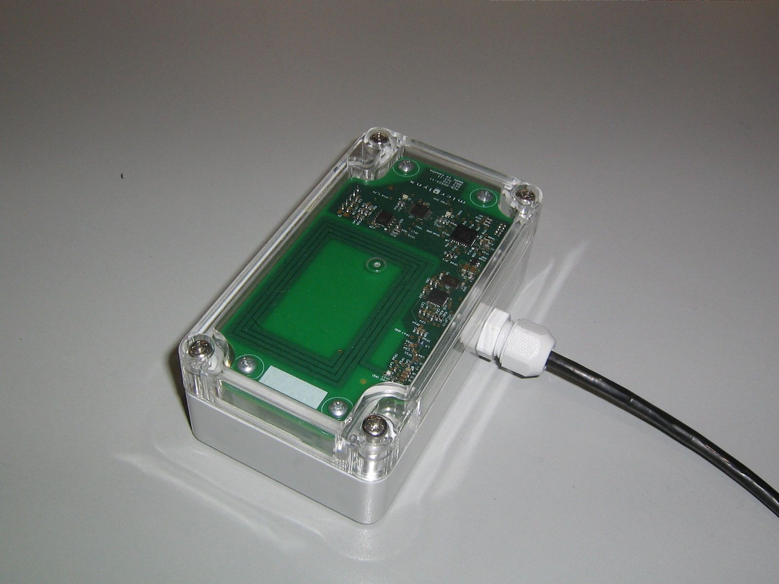
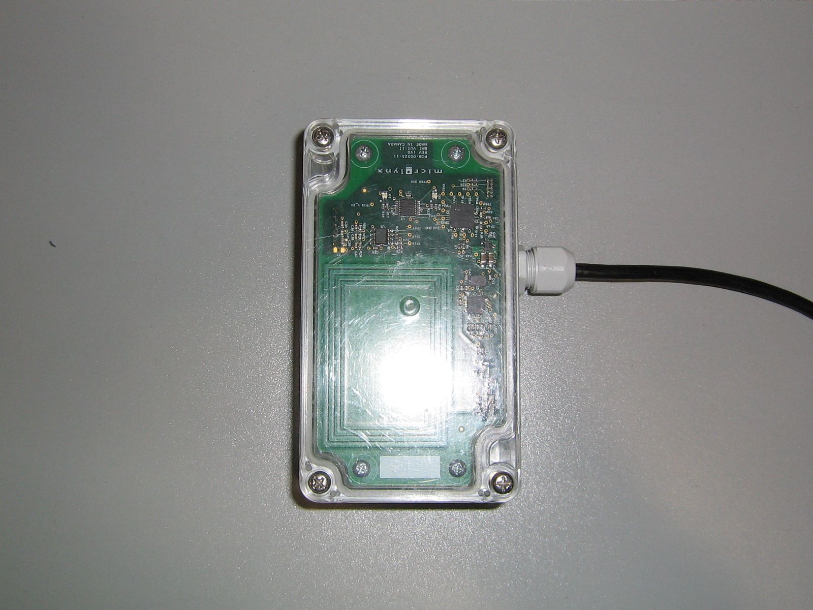
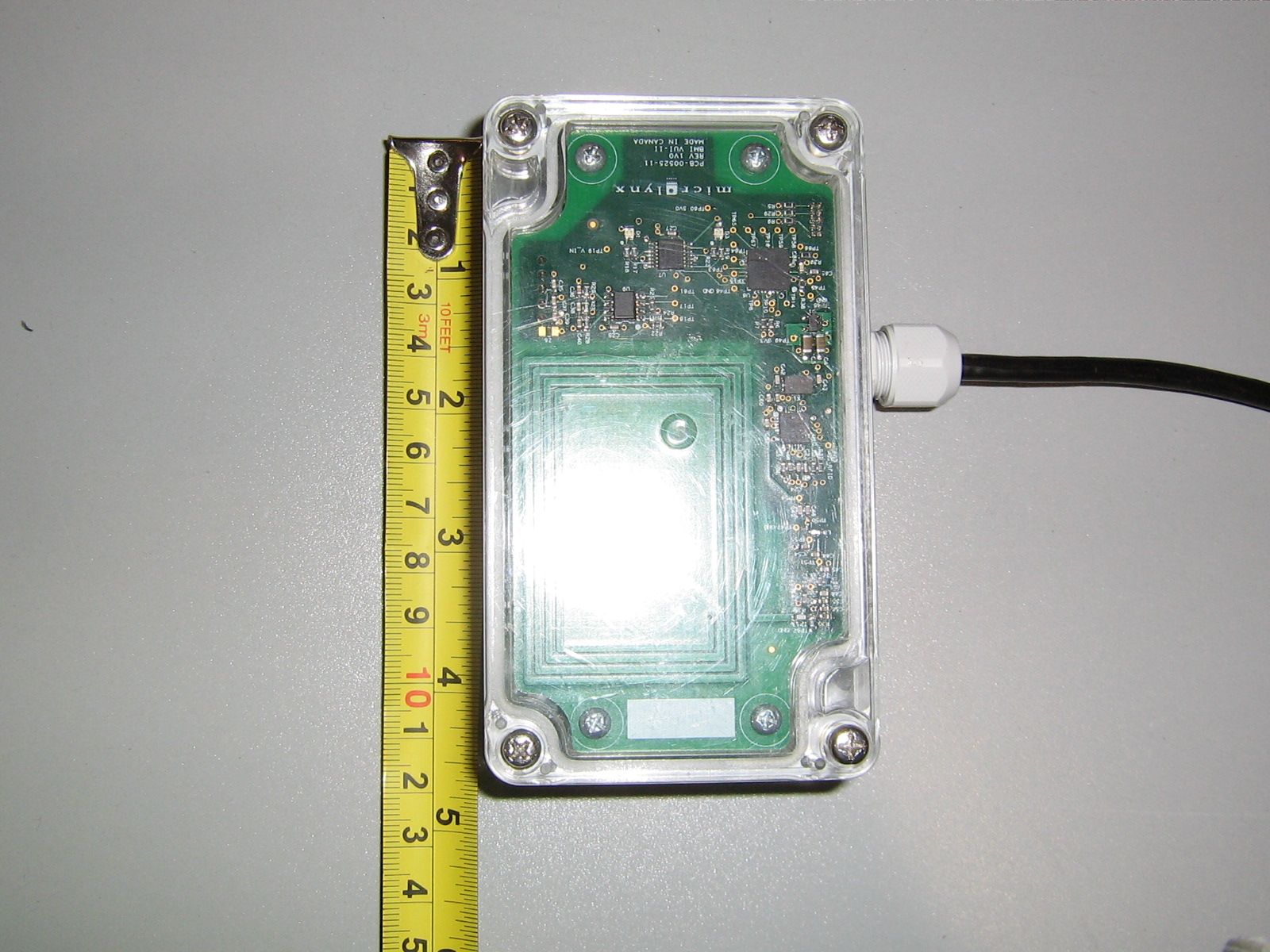
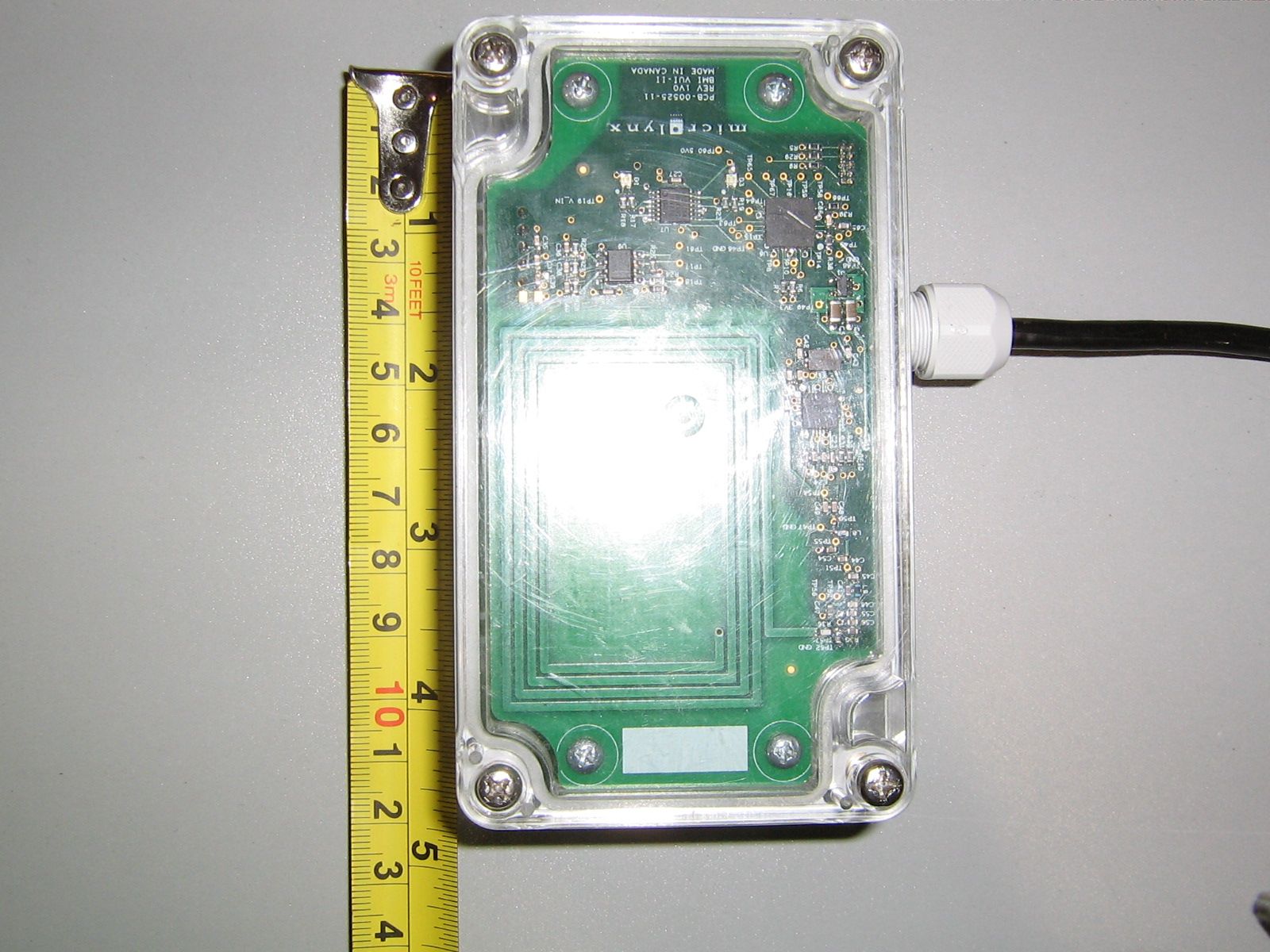
- VUI-II
- Frequency Range
- 13.56000000 - 13.56000000
- Company
- BMI Technologies Inc.
- Country
- Canada
Documents & Files
Document Text
Text extracted from the exhibit documents filed with the FCC. Open a document above to read the original.
Users Manual
BMI TECHNOLOGIES INC. #3, 7317 12 St SE, Calgary, Alberta CANADA T2H 2S6 Toll-free: 1 800 563-8867 Tel: (403) 244-3901 Fax: (403) 229-0135 INSTRUCTION MANUAL Document #RF1 Rev. 14 G FORCE PLUS RF Instruction Manual TABLE OF CONTENTS Doc #RF1 Rev. 13 i May/10 INTRODUCTION ....................................................................................................................... 5 SYSTEM DIAGRAM ........................................................................................................... 5 SYSTEM FEATURES ......................................................................................................... 5 PARTS LIST ....................................................................................................................... 6 FCC AND IC REGULATORY DECLARATIONS ................................................................. 7 Special Accessories .................................................................................................... 7 Interference ................................................................................................................ 7 Component Changes or Modifications ........................................................................ 7 RF Exposure Warning................................................................................................. 7 FCC ET DÉCLARATIONS IC RÉGLEMENTAIRES ............................................................ 8 Accessoires spéciaux ................................................................................................. 8 Interférence ................................................................................................................ 8 Les changements ou modifications de composants .................................................... 8 Avertissement d'exposition RF .................................................................................... 8 VEHICLE AND SOFTWARE INTERFACE TECHNIQUES ................................................. 9 Vehicle Interface and Cards ........................................................................................ 9 Software Interface and Cards ..................................................................................... 9 INSTRUCTION MANUAL CONVENTIONS .......................................................................10 QUICK-START ..............................................................................................................10 INSTALLATION INSTRUCTIONS ............................................................................................11 VEHICLE MONITOR AND INTERFACE ............................................................................11 Component Overview ................................................................................................11 Electrical Description .................................................................................................11 Installation Steps .......................................................................................................12 SOFTWARE AND INTERFACE ........................................................................................17 System Requirements................................................................................................17 Software Interface Installation ....................................................................................17 Software Installation ..................................................................................................17 RF TRANSCEIVERS .........................................................................................................19 Component Overview ................................................................................................19 Installation Steps for ZT802.3 ....................................................................................19 SYSTEM SETUP ......................................................................................................................21 SOFTWARE ......................................................................................................................21 Starting the Software .................................................................................................21 Navigation ..................................................................................................................22 Server Settings ..........................................................................................................23 System Settings .........................................................................................................23 Zones ........................................................................................................................25 If you are setting up a Host Transceiver ........................................................................... 26 If you are setting up a ZT 802.3 Transceiver .................................................................... 27 Authorization Groups .................................................................................................30 Add an Authorization Group .............................................................................................. 30 Create a Vehicle Inspection Checklist .............................................................................. 32 Edit the Custom Checklist ................................................................................................. 34 Edit an Authorization Group .............................................................................................. 35 Vehicles .....................................................................................................................36 Add a Vehicle .................................................................................................................... 36 Edit a Vehicle ........................................................…
Text truncated - open the document above for the full version.
Users Manual
BMI TECHNOLOGIES INC. Bay 3 7317 12 Street SW, Calgary, Alberta CANADA T2H 2S6 Toll-free: 1 800 563-8867 Tel: (403) 244-3901 Fax: (403) 229-0135 VEHICLE MONITOR INSTALLATION INSTRUCTIONS G FORCE PLUS RF Vehicle Monitor Installation Instructions 1 June/07 BMI Warranty Policy BMI Technologies Inc. (BMI) warrants to the original customer that its products are of the highest standards and every effort has been made to deliver a product that is free of defect. Should the product fail within one (1) year from date of sale, BMI will, at its discretion, repair or replace the defective product at no charge. If your product does not perform as promised, contact BMI Technical Assistance (1-800-563-8867) for an assessment of the problem. To aid in troubleshooting, be prepared to provide product Serial Number(s). Before your product can be returned, you will require a Return Goods Authorization number (RGA#). Product must be shipped at your cost via traceable means within 30 days of the issue date of the RGA. Any charges associated with shipping due to incorrect paperwork will be charged back to you. Please contact BMI for any needed assistance. Returned product cannot be accepted at BMI unless the RGA# is clearly labeled on the outside of the package. Final warranty determination is at the discretion of BMI on receipt and inspection of the returned product. No warranty applies where there is evidence of misuse, improper installation, unauthorized modifications or repairs, vandalism, fire, or contact with corrosive materials. Defacing hardware in any way, will limit warranty options to repair and return only. Defaced units will not be replaced or credited If product returned under warranty is deemed to work properly, the customer will be responsible for a $50.00 No Fault Found fee as well as freight charges to return the product. This warranty applies to product only and does not include labor or any other charges. BMI Return Policy To return unused product in its original packaging, contact BMI Order Desk (1-800-563-8867) for a Return Goods Authorization number (RGA#). Returns are accepted within 90 days of the original invoice date. Returns must be shipped at your cost via traceable means within 30 days of the issue date of the RGA. Returns cannot be accepted at BMI unless the RGA# is clearly labeled on the outside of the package. Credits issued for returned product are subject to a 25% handling fee and are at the discretion of BMI Technologies Inc. after inspection of the returned goods. No returns on keys or cards. Credits will be issued within 6-8 weeks. Please note BMI does not issue checks, credits will be applied toward the customer’s account. Non-Warranty Repairs To ship items for non-warranty repair, contact BMI Order Desk (1-800-563-8867) for a Return Goods Authorization number (RGA#) and to provide a Purchase Order number for the work to be done. Items must be shipped at your cost and cannot be accepted at BMI unless the RGA# is clearly labeled on the outside of the package. G FORCE PLUS RF Vehicle Monitor Installation Instructions June/07 2 FCC AND IC REGULATORY DECLARATIONS Federal Communications Commission (FCC) and Industry Canada (IC) regulations require the inclusion of this section in the Instruction Manual. SPECIAL ACCESSORIES The provided antenna, which operates in the 902 to 928 MHz frequency band, and antenna extension cable, must be used with the G FORCE PLUS RF Host Transceiver, G FORCE PLUS RF Zone Transceiver and G FORCE PLUS RF Vehicle Monitor. No substitutions are allowed. INTERFERENCE The G FORCE PLUS RF Vehicle Monitor antenna and the G FORCE PLUS Vehicle Interface may not be located closer than 20cm to each other. These devices comply with Part 15 of the FCC Rules. Operation is subject to the following two conditions: (1) the devices may not cause harmful interference, and (2) the devices must accept any interference received, including interference that may cause undesired operation. COMPONENT CHANGES OR MODIFICATIONS Changes or modifications not expressly approved by the party responsible for compliance could void the user’s authority to operate the G FORCE PLUS Vehicle Interface, G FORCE PLUS Data Logger, G FORCE PLUS RF Vehicle Monitor, G FORCE PLUS RF Host Transceiver, and G FORCE PLUS RF Zone Transceiver. RF EXPOSURE WARNING The following warning applies to the G FORCE PLUS Vehicle Interface, G FORCE PLUS RF Vehicle Monitor, G FORCE PLUS RF Host Transceiver, and G FORCE PLUS RF Zone Transceiver: WARNING: This device exceeds the FCC/IC requirements for RF exposure when the antenna used for this transmitter has a separation distance of at least 20 cm from all persons and must not be co-located or operating in conjunction with any other antenna or transmitter which is closer than 20 cm. The installer of this radio equipment must ensure that the antenna is located or pointed such that it does not emit RF field in excess of Health Canada limits for the general population as indicated by Safety Code 6. G FORCE PLUS RF Vehicle Monitor Installation Instructions 3 June/07 INSTALLATION INSTRUCTIONS This section provides the installation instructions for the G FORCE PLUS RF system. VEHICLE MONITOR AND INTERFACE The Vehicle Monitor and Vehicle Interface installation instructions follow. A copy is also included with each Vehicle Monitor shipped. Component Overview Electrical Description Input Fuse (F1) 12 – 60 volts 1A DC Slow Lift Interrupt Relay Fuse (F2) Max 60 volts 3.5A DC Slow Secondary Alarm Relay Fuse (F4) Max 60 volts 3A DC Slow Horn Relay Fuse (F3) Max 60 volts 3A DC Slow NOTE! Vehicle Monitor and Vehicle Interface installation may be done at the same time as the Software and Software Interface installation. G FORCE PLUS RF Vehicle Monitor Installation Instructions June/07 4 Installation Steps NOTE! Wires and cables should be installed to avoid chafing and excess slack. Cable ties, clamps, grommets, looms, sleeves, supplementary insulation, conduit, and routing are …
Text truncated - open the document above for the full version.
Block Diagram
VUI-II Block Diagram Switching Regulator RS422 Transceiver and Filter Microcontroller RFID Driver Chip Matching Circuit PCB Loop Antenna System Power 13.56 MHz Crystal 13.56 MHz Osc Out RPT - 00525 - 004 VUI - II Block Diagram Drawn by: Ken Mouratidis Microlynx Systems Ltd 26 Nov 2012 Cable to VM
Block Diagram
VUI-II Block Diagram Switching Regulator RS422 Transceiver and Filter Microcontroller RFID Driver Chip Matching Circuit PCB Loop Antenna System Power 13.56 MHz Crystal 13.56 MHz Osc Out RPT - 00525 - 004 VUI - II Block Diagram Drawn by: Ken Mouratidis Microlynx Systems Ltd 26 Nov 2012 Cable to VM
Test Report
CANADA: 16 - 211 Schoolhouse Street Coquitlam, British Columbia Canada V3K 4X9 Company Name: BMI Technologies Report Number: E10531-1201 Rev 0.0 Page 1 of 32 ELECTROMAGNETIC COMPATIBILITY TEST REPORT TO CFR 47 FCC Part 15, Subpart C, Section 15.225 Industry Canada RSS 210, Issue 8 Industry Canada RSS-Gen, Issue 3 INTENTIONAL TRANSMITTER STANDARDS FOR LICENCE-EXEMPT RADIO APPARATUS & INTENTIONAL RADIATORS OPERATING WITHIN THE BAND 13.110-14.010 MHz Report Number: E10531-1201 Issue: Revision 1.0 Date of Issue: January 29 th , 2013 Number of Pages: 32 Testing Laboratory: Quality Auditing Institute Address: #16 – 211 Schoolhouse Street, Coquitlam, BC, V3K 4X9, Canada ISO 17025 Accreditation: Standard Council of Canada: Accredited Laboratory No. 743 International Accreditation Service Inc.: Accredited Laboratory No. TL-239 This report has been completed in accordance with the requirements of ISO/IEC 17025. Test results contained in this report are within QAI Laboratories ISO/IEC 17025 accreditation. QAI Laboratories authorizes the applicant to reproduce this report provided it is reproduced in its entirety and for the use by the company’s employees only. CANADA: 16 - 211 Schoolhouse Street Coquitlam, British Columbia Canada V3K 4X9 Company Name: BMI Technologies Report Number: E10531-1201 Rev 0.0 Page 2 of 32 Applicant’s Name: BMI Technologies Address: #3 7317 12 Street SE, Calgary, AB, T2H 2S6 Phone: (403) 244-3901 Fax: Primary Contact: Clayton Johnson E-mail: [email protected] Test Specifications Standards: Industry Canada RSS 210 Issue 8, Industry Canada RSS-Gen Issue 3, CFR 47 FCC Part 15 Subpart C Section 15.225. Procedures: As called by the standards above. Non-Standard Test Methods: NA Test Item Description: Vehicle RFID Card Reader Trade Mark: Manufacturer: BMI Technologies Model Number: RFVI-II FCC ID # SYXRFVI-II IC ID # 6205A-VUI02 Company Name: BMI Technologies Report Number: E10531-1201 Rev 0.0 Page 3 of 32 Table of Contents Section I: EMC Test Description ......................................................................................................... 5 Testing Location .................................................................................................................. 5 EUT Receiving Details ........................................................................................................ 5 Environmental Test Conditions: Indoors ............................................................................. 5 EMC Test Summary ............................................................................................................ 6 Revision History .................................................................................................................. 7 Measurement Uncertainty ................................................................................................... 8 Test Equipment List ............................................................................................................ 8 Semi-Anechoic Chamber Equipment List ................................................................... 8 Measurement Software List ......................................................................................... 8 Temperature Chamber Equipment List ....................................................................... 8 Section II: Equipment Under Test Information ..................................................................................... 9 EUT Testing Information ..................................................................................................... 9 Summary of On Board Frequencies.................................................................................... 9 Auxiliary Equipment ............................................................................................................. 9 EUT Cabling Configuration ................................................................................................. 9 Appendix A: Report of Measurement Data and Plots ............................................................................ 10 Radiated Emissions 10 kHz – 30 MHz .............................................................................. 10 Carrier / Fundamental Emission ................................................................................ 12 Radiated Emissions: 10 kHz – 150 kHz .................................................................... 14 Radiated Emissions: 150 kHz – 13 MHz ................................................................... 16 Radiated Emissions: 13 MHz – 14 MHz .................................................................... 18 Radiated Emissions: 14 MHz – 30 MHz .................................................................... 20 Radiated Emissions 30 MHz – 1000 MHz ......................................................................... 22 Radiated Emissions: 30 MHz – 1000 MHz ................................................................ 24 Occupied Bandwidth ......................................................................................................... 25 Transmitter Frequency Stability ......................................................................................... 27 Frequency Vs. Voltage at 20°C ................................................................................. 28 Frequency Vs. Temperature ...................................................................................... 28 Company Name: BMI Technologies Report Number: E10531-1201 Rev 0.0 Page 4 of 32 Appendix B: EUT Photos During EMC Testing ..................................................................................... 29 Company Name: BMI Technologies Report Number: E10531-1201 Rev 0.0 Page 5 of 32 Section I: EMC Test Description Testing Location Testing Laboratory: Quality Auditing Institute Laboratory Address: #16 – 211 Schoolhouse Street, Coquitlam, BC, V3K 4X9, Canada Associated EMC Laboratory: Quality Auditing Institute: …
Text truncated - open the document above for the full version.
Contact Information
Applicant
Clayton Johnson(Head of Support)
Non-Technical Contact
Microlynx Systems LtdKen Mouratidis
[email protected](403)275-7346
Test Firm
Quality Auditing Institute Ltd.Lawrence Gibson
[email protected]604-527-8378
Technical Specifications
| # | Rule Parts | Frequency Range | Power Output |
|---|---|---|---|
| 1 | 15C | 13.56 MHz - 13.56 MHz | - |
Other Applications from BMI Technologies Inc.
SYXVUI00
Dec 14, 2005Vehicle User Interface RFID Reader
Equipment Class
DXX - Part 15 Low Power Communication Device Transmitter