SYZKR100FEarphone Guide
Kennet Co., Ltd.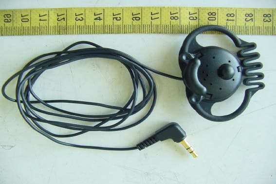
Click to zoom
Application Details
- Equipment Class
- TNT - Licensed Non-Broadcast Transmitter Worn on Body
- Date of Grant
- Mar 15, 2005
- Application Purpose
- Original Equipment
- Date of Application
- Mar 15, 2005
- Equipment Note
- Earphone Guide
- Frequency Range
- 794.81500000 - 805.31500000
- Company
- Kennet Co., Ltd.
- Country
- Japan
Documents & Files
Document Text
Text extracted from the exhibit documents filed with the FCC. Open a document above to read the original.
Users Manual
User's Guide UHF-PLL TRANSLATION TOUR-GUIDE SYSTEM 1. Power Switch and Volume Control On : Turn the button in a clockwise direction until the turn-on sound is heard. In 0.5 seconds, the receiver will be in the standby mode. Off : Turn the button completely in a counter-clockwise direction until the turn-off sound is heard. In 0.5 seconds, the receiver will stop its functioning completely. Volume Control : After the receiver is turned on, turning in a clockwise direction will increase the volume. A counter-clockwise direction will decrease the volume. Note : When the receiver is on a standby mode, do lower the volume to avoid damaging the ears when the earphone is too loud. 2. Receiving Light & Low Power Signal Light Green Light : When the receiver receives a RF signal from the emitter, the LED will indicate green light Red Light : After the receiver has been in use for some time and the battery power is insufficient, the LED will indicate red. At this time, it is necessary to change to fully-charged standard-sized batteries. 3. Earphone Output : To use a 3.5Double ear piece or single ear piece 4. CH Switch: A choice of 16 different frequencies 5. AUX OUT : Can be connected to an AMP and transmitted through a speaker. ( AUX IN : Can be connected to an MP3 and transmitted volume to receiver (receiver) Transmission) 6. Battery Box : 1. When the power signal light is red, please turn off the receiver. Make sure that the machine is not operating before removing the old batteries and changing to new ones. 2. When changing batteries, the standard AAA size must be used. Please also check that there is no power leakage in the batteries. When there is no problem, put in new batteries to ensure the quality and lifespan of the machine. Basic Operation (1) (2)(3) (4) (5) (6) Main Features Transmission : 1. This machine is certified to have met the FCC standard. 2. Transmission Output 10Mv 16ch 3. Simple Small-sized Emitter and Receiver 4. Usable without connection to external microphone 5. Built-in Antenna Rrceiver 1 This machine is certified to have met the FCC standard. 2. Specially designed for low power reception use. Light-weight and easy to operate. Noise control and 16 different frequencies to choose from. Built-in Mic. built-in microphone (TX) 1. Transmitter with built-in condenser mini mic. or external microphone (Mic. jack). or Aux - in (MP3) 2. Aux-in (MP3) ON. The External Mic. and Built-in mic. OFF. External mic. ON. The Aux-in (MP3) ON. Built-in mic. OFF Aux - in (TX) External microphone Caution for use 1. Avoid placing machine under exposure to direct sunlight or near heating origin. Avoid humid and water source areas. 2. Avoid keeping and using machine in a car with no air-condition for a long period of time. (especially in summer) 3. Please use a piece of soft damp cloth dabbed with a neutral cleansing detergent when wiping the machine exterior. Avoid using a wet cloth to avoid any damage due to liquid intrusion. 4. On rainy days or in incidents when the machine comes into contact with water, turn off the power immediately and remove the batteries. Then place the machine in a dry area until the machine is completely dry before the next usage. 5. When the machine breaks down, turn off the power immediately and remove the batteries. Then allow the professional personnel from the authorized agents or main office to fix the problem. Specifications Transmission 1. Frequency Range 740 ~ 806 MHz 16CH (250kHZ) 2. Communication System Single Emission 3. EW F3E 4. Output Power 10mW 5. Battery AAA sized 1.5V x 2 6. Operation Temperature -10 ~ + 50 Receiver 1.Receiving Frequency 740M ~ 806MHz 2.Channel Selection 16CH (250K Frequency Resolution) 3.Receiving System Phase Lock Loop 4.Audio 3.5 mm ear piece output *1 (3.5mm AUX OUT *1) 5.Output Frequency 20Mw (16 Load) 6.Operation Temperature -10 ~ + 50 7.Battery AAA sized 1.5V x 2 8.Measurement 92.7 x 62 x 21.1mm 9.Weight 87.5 g 10.Reception Distance 60M ~ 70M Note Usage in hospitals is only allowed if approval is given. The emission of this machine could affect special medical equipment. Do not turn on the power supply in specific restricted areas. Warning When on flight, do not activate the transmitter. When machine is operating, it could disrupt the flight instrument and result in a malfunction When To Change The Battery Once the power supply is turned on for some time, you should first turn off the power supply and then change the batteries if (a)there is a shortening in the reception distance (b)the sound quality deteriorate (c)the 'Weak Power Supply' signal appears (i.e. an orange light (P.S. : When the power signal is red, it will stop functioning automatically.)
External Photos
ETC Report No.:ET93R-10-109-04 Sheet 1 of 14 Sheets FCC ID.: SYZKR100F Rev. 2.0 CONSTRUCTED PHOTOS of EUT A. 744-752MHz 1. Front View of EUT 2. Rear View of EUT ETC Report No.:ET93R-10-109-04 Sheet 2 of 14 Sheets FCC ID.: SYZKR100F Rev. 2.0 CONSTRUCTED PHOTOS of EUT 3. Side View of EUT 4. SideView of EUT ETC Report No.:ET93R-10-109-04 Sheet 3 of 14 Sheets FCC ID.: SYZKR100F Rev. 2.0 CONSTRUCTED PHOTOS of EUT 5. Top View of EUT 6. Bottom View of EUT ETC Report No.:ET93R-10-109-04 Sheet 4 of 14 Sheets FCC ID.: SYZKR100F Rev. 2.0 CONSTRUCTED PHOTOS of EUT 7. Front View of Cable 8. Front View of Cable ETC Report No.:ET93R-10-109-04 Sheet 8 of 14 Sheets FCC ID.: SYZKR100F Rev. 2.0 CONSTRUCTED PHOTOS of EUT B. 794-806MHz 1. Front View of EUT 2. Rear View of EUT ETC Report No.:ET93R-10-109-04 Sheet 9 of 14 Sheets FCC ID.: SYZKR100F Rev. 2.0 CONSTRUCTED PHOTOS of EUT 3. Side View of EUT 4. SideView of EUT ETC Report No.:ET93R-10-109-04 Sheet 10 of 14 Sheets FCC ID.: SYZKR100F Rev. 2.0 CONSTRUCTED PHOTOS of EUT 5. Top View of EUT 6. Bottom View of EUT ETC Report No.:ET93R-10-109-04 Sheet 11 of 14 Sheets FCC ID.: SYZKR100F Rev. 2.0 CONSTRUCTED PHOTOS of EUT 7. Front View of Cable 8. Front View of Cable
Internal Photos
ETC Report No.:ET93R-10-109-04 Sheet 5 of 14 Sheets FCC ID.: SYZKR100F Rev. 2.0 CONSTRUCTED PHOTOS of EUT 9. Internal View of EUT (744-752MHz) ETC Report No.:ET93R-10-109-04 Sheet 6 of 14 Sheets FCC ID.: SYZKR100F Rev. 2.0 CONSTRUCTED PHOTOS of EUT 10. Component View of PCB 11. Solder View of PCB ETC Report No.:ET93R-10-109-04 Sheet 7 of 14 Sheets FCC ID.: SYZKR100F Rev. 2.0 CONSTRUCTED PHOTOS of EUT 12. Component View of PCB 13. Solder View of PCB ETC Report No.:ET93R-10-109-04 Sheet 12 of 14 Sheets FCC ID.: SYZKR100F Rev. 2.0 CONSTRUCTED PHOTOS of EUT 9. Internal View of EUT (794-806MHz) ETC Report No.:ET93R-10-109-04 Sheet 13 of 14 Sheets FCC ID.: SYZKR100F Rev. 2.0 CONSTRUCTED PHOTOS of EUT 10. Component View of PCB 11. Solder View of PCB ETC Report No.:ET93R-10-109-04 Sheet 14 of 14 Sheets FCC ID.: SYZKR100F Rev. 2.0 CONSTRUCTED PHOTOS of EUT 12. Component View of PCB 13. Solder View of PCB
Parts List/Tune Up Info
KR-100J-T Required information according to FCC 2.1033(c)(1)-(9) (1) ApplicantKENNET CO.,LTD. AddressFundex Ginza Bild. 5F, 1-9-4 Shintomi, Chou-ku, Tokyo, Japan (2) manufactureE-J ELECTRONICS CO., LTD. Address4F, NO.11, Lane 125, Sec 1, Kuo Kwang Road Ta Li City, Taichung Hsien Taiwan R .O .C . (3) FCC IDSYZKR100F (4) Installation and Operation Instructions: Please fine user’s manual attached. (5) Type of Emission172KF3E (2M+2D: 2X38+2X48=172kHz) (6) Frequency Range740-806 MHz (7) Power limit of applicable partAccording to Part 74 subpart H, the maximum permissive power is 50mW. (8) The DC voltage applied to and DC current in to the several elements of the final RF amplifying deviceBattery 1.5V(AAA Size)*2PCS (9) Tune-up Procedure KR-100J-T Tune-up Procedure 1. The modulation level can adjust by VR4. 2. The audio frequency is modulated which can get RF signal via modulator VCO. 5. Adjust VC2 to correct the reference frequency. 6. The Osc. Signal coupled to drive amplifier Q9 and power amplifier Q8 to get better RF level.
Test Report
Rev. 2.0 FCC Part 74 Subpart H EMI TEST REPORT of E.U.T. : EARPHONE GUIDE (Transmitter) MODEL : KR-100F FCC ID. : SYZKR100F Working Frequency : 740-806MHz for APPLICANT : KENNET CO., LTD. ADDRESS : Fundex Ginza Bild. 5F, 1-9-4 Shintomi, Chou-ku, Tokyo, Japan Test Performed by ELECTRONICS TESTING CENTER, TAIWAN NO. 34, LIN 5, DING FU TSUN, LINKOU HSIANG TAIPEI HSIEN, TAIWAN, R.O.C. Tel:(02) 26023052 Fax:(02)26010910 http://www.etc.org.tw ; e-mail : [email protected] Report Number : ET93R-10-109-04 ETC Report No.:ET93R-10-109-04 FCC ID.: SYZKR100F Rev. 2.0 TEST REPORT CERTIFICATION Applicant : KENNET CO., LTD. Fundex Ginza Bild. 5F, 1-9-4 Shintomi, Chou-ku, Tokyo, Japan Manufacturer : E-J ELECTRONICS CO., LTD. 4F, No. 11, Lane 125, Sec. 1, Kuo Kwang Road, Ta Li City, Taichung Hsien, Taiwan, R.O.C. Description of EUT a) Type of EUT : EARPHONE GUIDEs (Transmitter) b) Trade Name : KENNET c) Model No. : KR-100F d) Power Supply : DC 3V Batteries e) Frequency Range : 740MHz-806MHz Regulation Applied : FCC Rules and Regulations Part 74 Subpart H (2003) I HEREBY CERTIFY THAT; The data shown in this report were made in accordance with the procedures given in ANSI C63.4 and the energy emitted by the device was founded to be within the limits applicable. I assume full responsibility for accuracy and completeness of these data. Note: 1. The result of the testing report relate only to the item tested. 2. The testing report shall not be reproduced expect in full, without the written approval of ETC. Issued Date : Feb. 21, 2005 Test Engineer : (Vicent Chang) Approve & Authorized Signer : Will Yauo, Manager EMC Dept. II of ELECTRONICS TESTING CENTER, TAIWAN ETC Report No.:ET93R-10-109-04 FCC ID.: SYZKR100F Rev. 2.0 Table of Contents Page 1 GENERAL INFORMATION...................................................................................................1 1.1 Product Description....................................................................................................................1 1.2 Characteristics of Device:...........................................................................................................1 1.3 Test Methodology......................................................................................................................1 1.4 Test Facility................................................................................................................................1 2 REQUIREMENTS OF PROVISIONS.....................................................................................2 2.1 Definition....................................................................................................................................2 2.2 Frequencies Available.................................................................................................................2 2.3 Requirements for Radio Equipment on Certification.....................................................................2 2.4 Labeling Requirement.................................................................................................................3 3 OUTPUT POWER MEASUREMENT.....................................................................................4 3.1 Provision Applicable...................................................................................................................4 3.2 Measurement Procedure.............................................................................................................4 3.3 Test Data...................................................................................................................................6 3.4 Result Calculation.......................................................................................................................8 3.5 Test Equipment..........................................................................................................................8 4 MODULATION CHARACTERISTICS..................................................................................9 4.1 Provisions Applicable.................................................................................................................9 4.2 Measurement Method................................................................................................................9 4.3 Measurement Instrument...........................................................................................................10 4.4 Measurement Result.................................................................................................................10 5 OCCUPIED BANDWIDTH OF EMISSION.........................................................................14 5.1 Provisions Applicable...............................................................................................................14 5.2 Measurement Method..............................................................................................................14 5.3 Occupied Bandwidth Test Equipment.......................................................................................14 5.4 Bandwidth Measured...............................................................................................................15 6 FIELD STRENGTH OF EMISSION.....................................................................................17 6.1 Provisions Applicable...............................................................................................................17 6.2 Measurement Procedure...........................................................................................................17 6.3 Measuring Instrument...............................................................................................................18 6.4 Measuring Data........................................................................................................................19 6.5 Radiated Measurement Photos......................................................................…
Text truncated - open the document above for the full version.
Test Setup Photos
ETC Report No.:ET93R-10-109-04 Sheet 27 of 50 Sheets FCC ID.: SYZKR100F Rev. 2.0 6.5 Radiated Measurement Photos
Contact Information
Applicant
Masashi Yukishita
Test Firm
Electronics Testing Center, TaiwanWill Yauo
Technical Specifications
| # | Rule Parts | Frequency Range | Power Output | Emission | Tolerance |
|---|---|---|---|---|---|
| 2 | 74 | 794.815 MHz - 805.315 MHz | 400.00 µW | 172KF3E | 0.005 % |
Other Applications from Kennet Co., Ltd.
SYZKR24GT
Feb 26, 20122.4GHz Digital Tour Guide System
Equipment Class
DTS - Digital Transmission System