SZBCSE035RF REMOTE CONTROL
Controlled Speed Engineering Ltd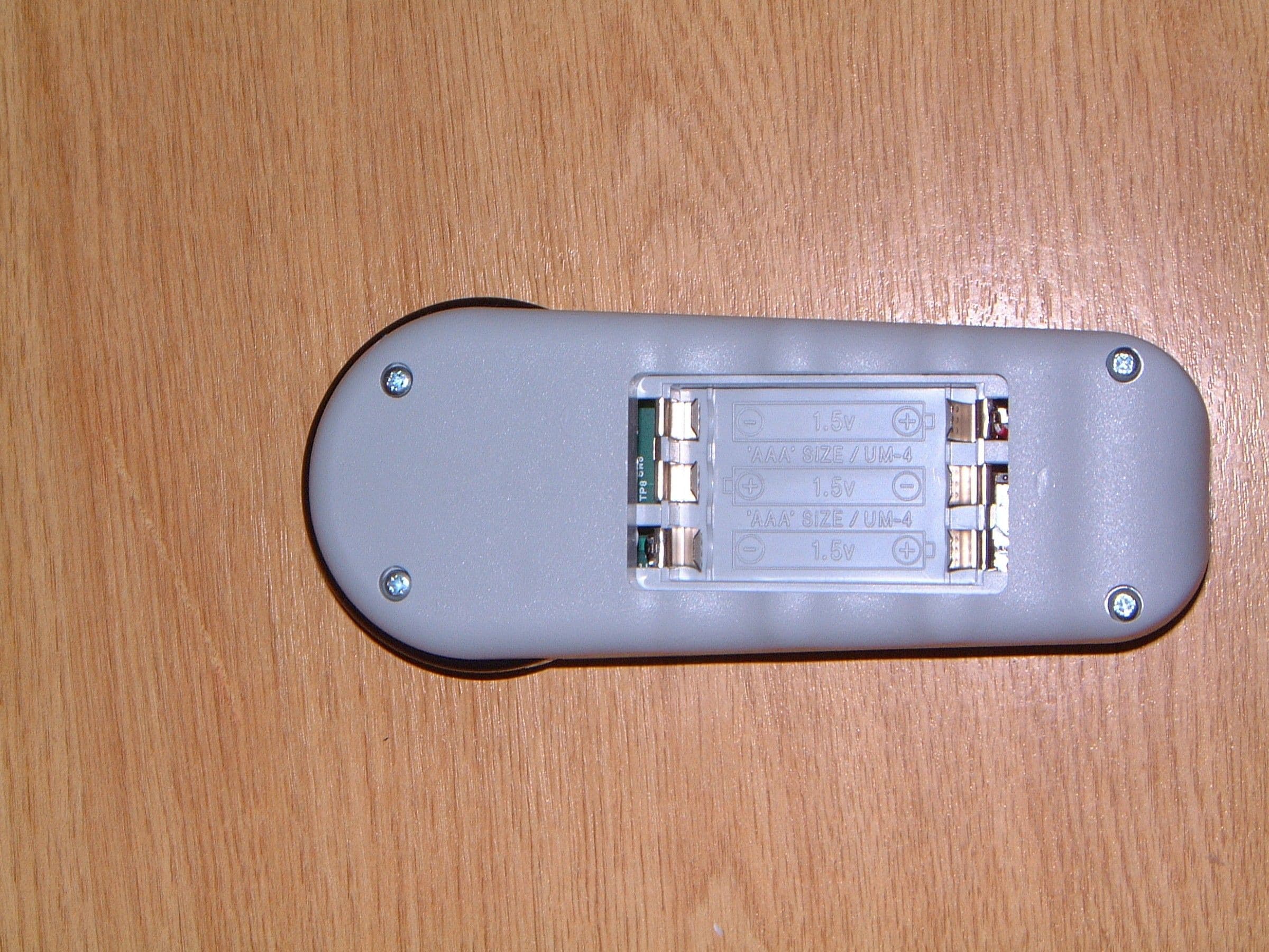
Click to zoom
Application Details
- Equipment Class
- DSC - Part 15 Security/Remote Control Transmitter
- Date of Grant
- Jun 29, 2005
- Application Purpose
- Original Equipment
- Date of Application
- Jun 29, 2005
- Equipment Note
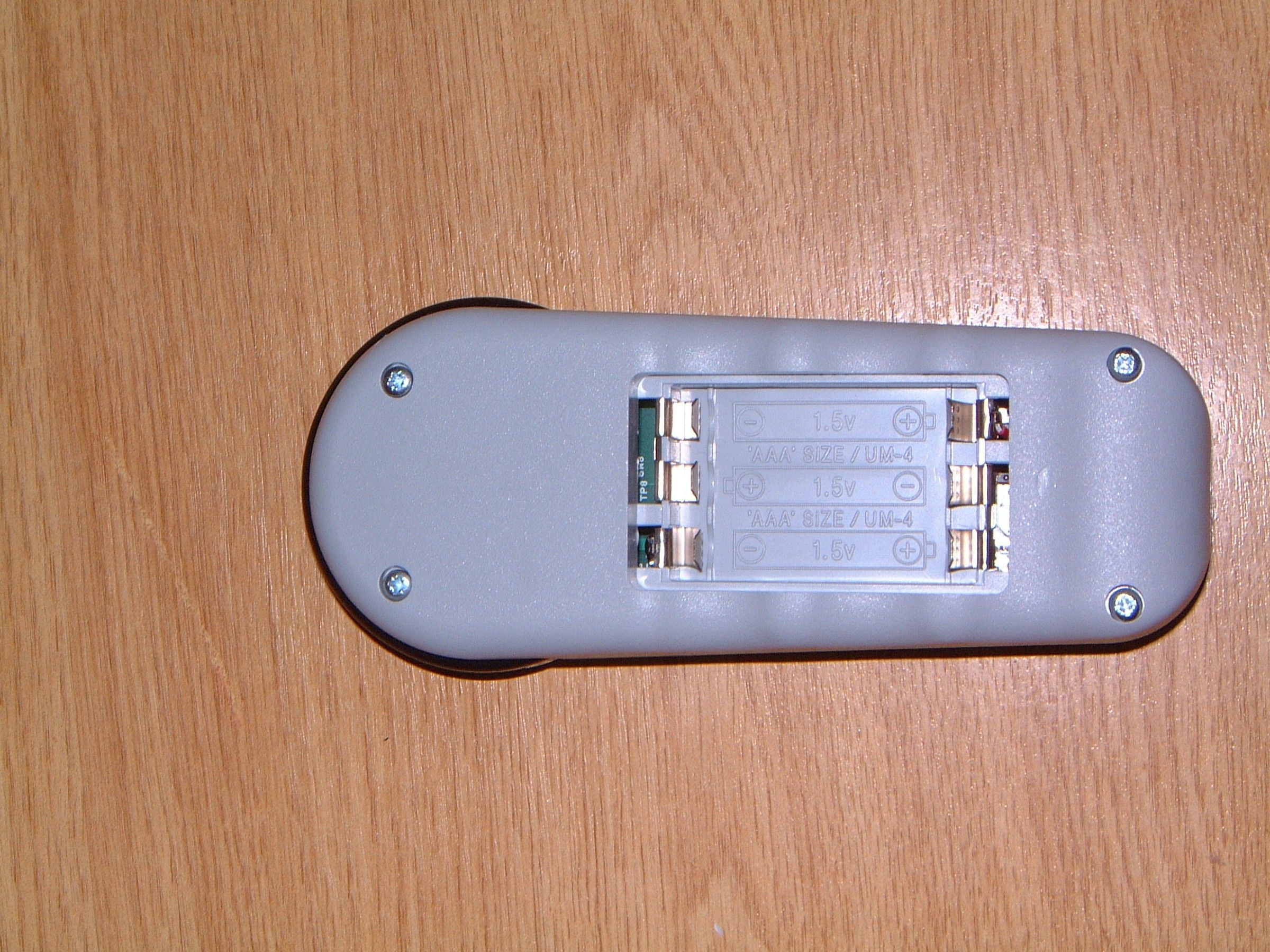
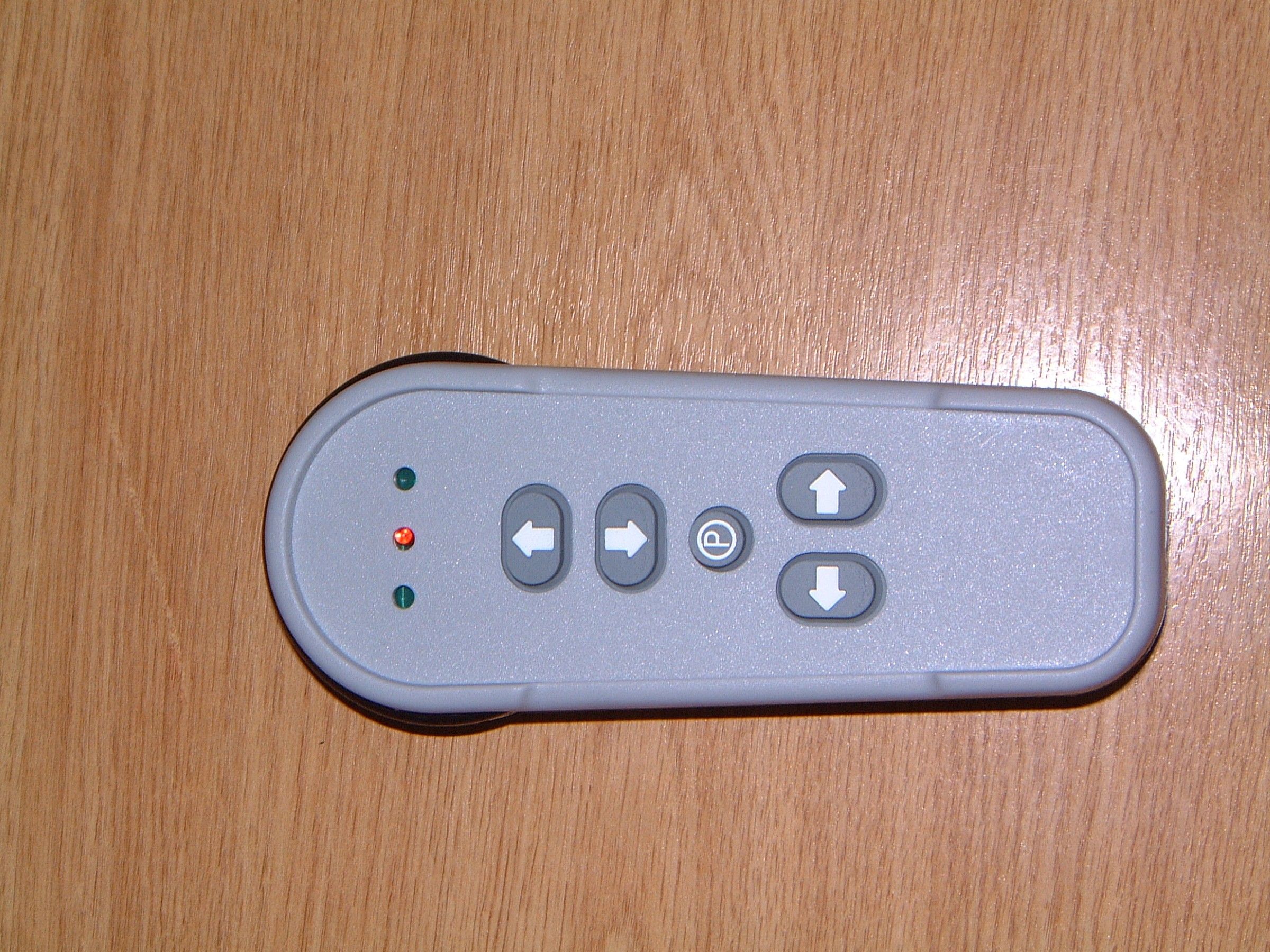
- RF REMOTE CONTROL
- Frequency Range
- 433.92000000 - 433.92000000
- Country
- United Kingdom
Documents & Files
Document Text
Text extracted from the exhibit documents filed with the FCC. Open a document above to read the original.
Users Manual
Sterling 1000 series 000137.52046/S issue 03 - 06 2005 Owners Operating Instructions 2 This manual is the intellectual copyright of Sterling Stairlifts. No changes may be made without prior consultation with Sterling. This manual may not be reprinted without the agreement of Sterling © Features of your Sterling 1000 Stairlift Thank you for selecting a Sterling stairlift. Please read these operating instructions carefully. Your Sterling stairlift has been designed and built with careful attention to detail. In order to obtain many years of trouble free use please follow the instructions, paying particular attention to the care and maintenance requirements. Sterling recommend that you do not undertake maintenance tasks other than routine care and cleaning explained in this handbook. Please contact your Sterling dealer or our Customer Service Department on Toll Free: 866 276 5483. Tel. 570 895 2480. Fax 570 895 24801. if your stairlift requires attention and we would be pleased to help you. Sterling have been accredited as conforming to the international standard of manufacturing, recognised by the award of ISO 9001. All Sterling stairlifts are built and tested to conform to the British Standard for stairlifts (BS5776) : 1996 as well as ISO 9386-2 and also carry the CE mark. Sterling are audited regularly to ensure we continue to conform to ISO 9001 and this provides you with the assurance of using a high quality and well manufactured product. IntroductionBritish Standards Contents Introduction2 British Standards2 Features of your Sterling 10003 Operating your Sterling4 Key Switch4 On/Off switch4 Operating lever5 Hand Control6 Hand Control (Radio Control)6 Folding your stairlift6 Folding linked seat and footrest8 Folding the powered footrest8 Operating the Swivel. (Not on perch seats)9 Operating the Powered Swivel9 Hinged Track - Powered (Optional)11 Hinged Track - Manual (Optional)11 Trapped articles11 Emergency hand winding instructions11 Servicing12 Battery Care and Charging12 Routine Care and Cleaning12 Warnings and Precautions13 Appendix 1 - Wiring diagram LH14 Appendix 2 - Wiring diagram RH15 Appendix 3 - PCB Dip Switch Settings16 Appendix 4 - Certificate of conformity19 3 This manual is the intellectual copyright of Sterling Stairlifts. No changes may be made without prior consultation with Sterling. This manual may not be reprinted without the agreement of Sterling. © Features of your Sterling 1000 Stairlift Perch Seat Option Safety Belt Important information about your stairlift which should be completed by the installation engineer. Installed by: .................................................................................................. (Company Name) Serial No .................................................................................................................................. Date of Installation ................................................................................................................... First service due ....................................................................................................................... Dealer Stamp Folding armrests Infra red remote control Revolving and Folding Seat with easy to operate controls. Powered or manual Folding footrest with safety edges Hinged Track Powered or Manual Simple to operate Key switch and control 4 This manual is the intellectual copyright of Sterling Stairlifts. No changes may be made without prior consultation with Sterling. This manual may not be reprinted without the agreement of Sterling © On/Off switch and indicator lamp (Seat in 90º rotated position) Operating your Sterling Stairlift Key Switch Your Sterling stairlift is fitted with a key switch (Fig. 2). The stairlift cannot be operated unless the key is inserted and turned to the operating position. The keyswitch is provided to enable you to lock the stairlift to prevent it being used by others (for example children). However it can be left in the operating position if desired. If you remove your key for safety reasons, please ensure you put it in a safe place. If the keyswitch is turned off while the lift is sitting over the charge contacts the lift will still charge. Fig. 2 On/Off switch As well as a key switch your stairlift is fitted with an Off/On switch (Fig. 3) on the front panel of the lift (below the seat). Ensure that this is left in the ‘ON’ position which is indicated by the green light being illuminated. If you intend to be away from home for a long period, and decide to switch off the mains supply, it is important that you also switch off the lift from this on/off switch. This will insure that the lift batteries will remain charged while you are away. Fig. 3 Switch in operating position 5 This manual is the intellectual copyright of Sterling Stairlifts. No changes may be made without prior consultation with Sterling. This manual may not be reprinted without the agreement of Sterling. © Operating your Sterling Stairlift Operating lever Before using your stairlift, MOST IMPORTANTLY please ensure the stairs are clear of other people, pets or any objects which may obstruct your stairlift. Then next, ensure arms, footplate and seat are folded down for use, as in the interests of your safety, the stairlift will not operate if they are not in their operating position (Fig. 5). BEFORE OPERATING YOUR STAIRLIFT ALWAYS FASTEN YOUR LAP BELT. Your Sterling stairlift is operated by simply pressing and holding the operating lever in the direction you wish to travel(Fig. 4). The stairlift will automatically stop when the switch is released or the stairlift has reached the end of its travel. PLEASE NOTE: In the interest of safety, initial activation of the stairlift is delayed by 1 second from pressing and holding the operating lever, to avoid accidental operation. If the switch is released while the lift is in motion, the lift will stop and a delay of 1 second will occur before the switch will re-start the lift. When cha…
Text truncated - open the document above for the full version.
Block Diagram
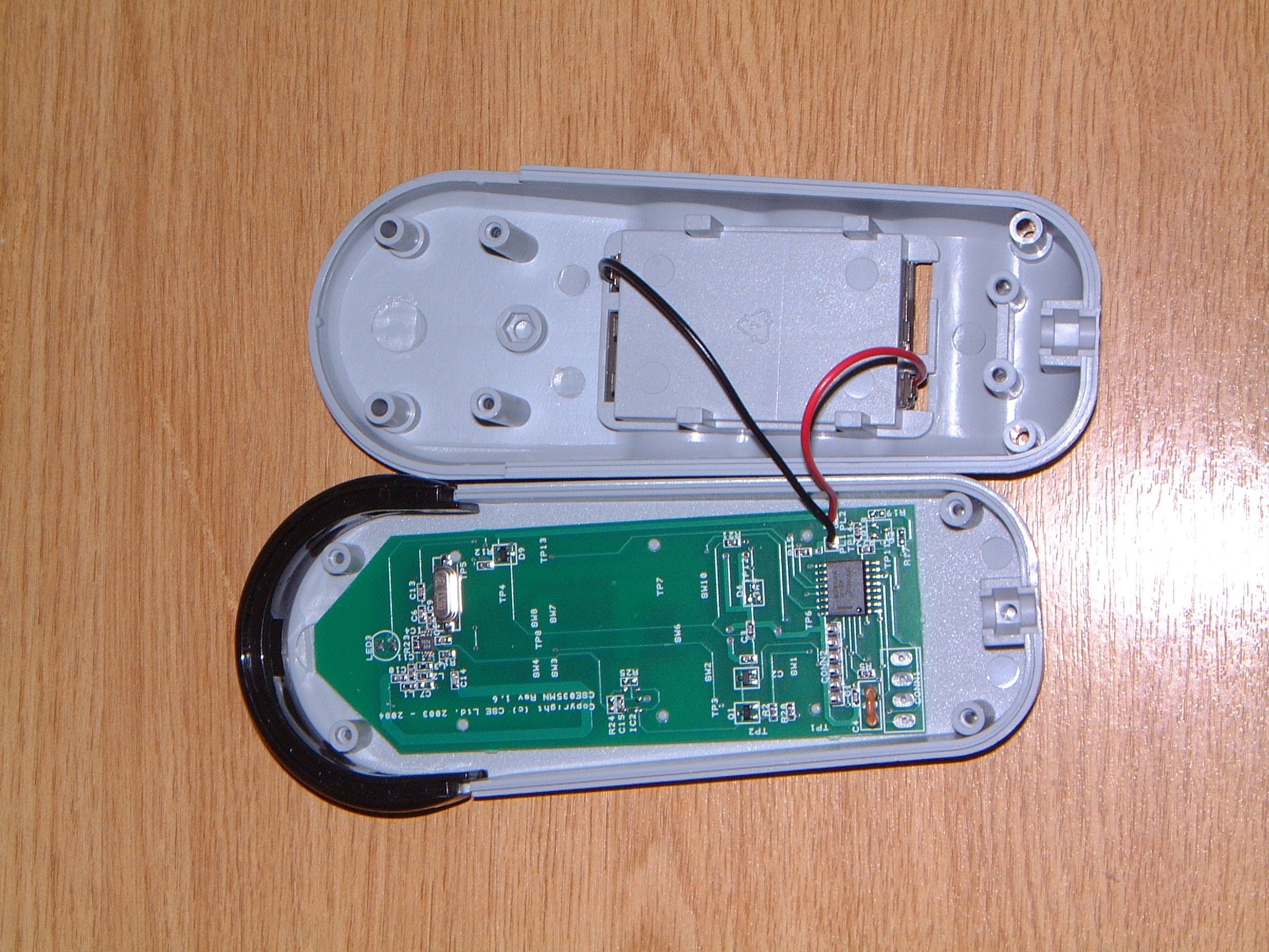
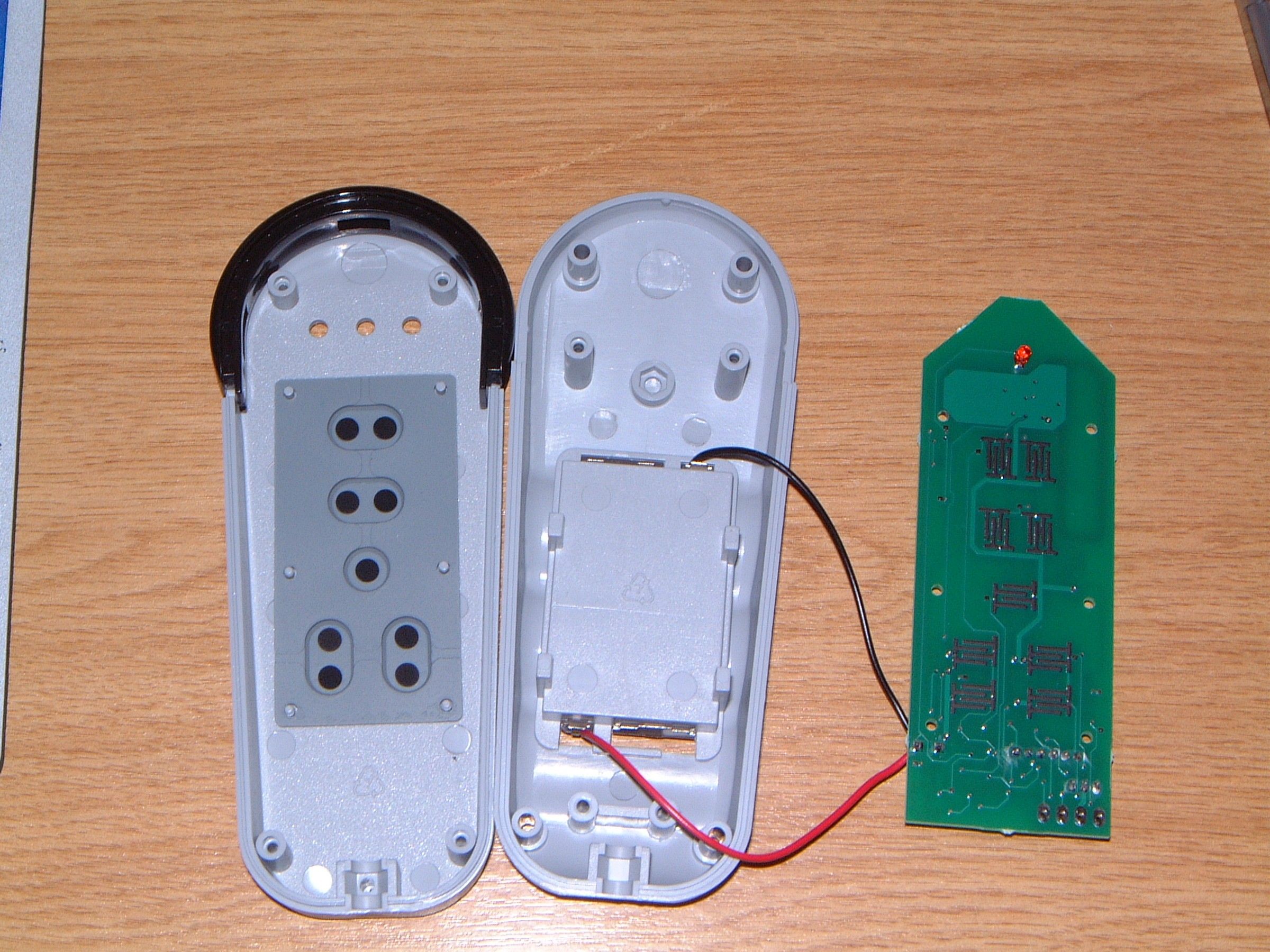
Controlled Speed Engineering Ltd FCC ID: 0012636486, Grantee code SZBCSE035 Transmitter Block Diagram Down up Park PCB Loop Antenna IN EEPROM Low Battery Detector T5754 RF Output Device 8 – BIT Microprocessor Out 2v Regulator Preliminary Specification ¾ Carrier Frequency 433MHz ¾ Operational Voltage: 4.5 ~ 2.7volts ¾ Current Consumption: <20mA (peak) ¾ Sleep Mode Current: < 10uA ¾ Antenna:2mm x 25mm x 34mm PCB loop ¾ Baud Rate: 1000bps ¾ Modulation Format: Return to Zero Frequency Shift Keying (FSK) ¾ Frequency Stability: +/- 100Hz
ID Label/Location Info
CS E Controlled Speed Engineering Ltd St Pegs House Thornhill Beck Lane Brighouse West Yorkshire HD6 4AH Tel (01484) 721981 Fax (01484) 721984 Copyright This drawing or design is confidential and is released on condition that it will not be lent copied replaced or otherwise be disclosed to any third party without the prior consent of Date File Name Drawn by Scale Title Issue No Do Not Scale Controlled Speed Engineering Ltd A. Fielden DRIVING TECHNOLOGY FORWARD 30/03/05 433 MHz FCC ID QF002/Min/CSE035/FCC_ID.Drw Revision 0 FCC ID: SZBCSE035 MINIVATOR THIS DEVICE COMPLIES WITH FCC RULES PART 15. OPERATION ISSUBJECT TO THE FOLLOWING TWO CONDITIONS: (1) THIS DEVICE MAY NOT CAUSE HARMFUL INTERFERENCE AND (2) THIS DEVICE MUST ACCEPT INTERFERENCE THAT MAYBE RECEIVED, INCLUDING INTERFERENCE THAT MAY CAUSE UNDESIRED OPERATION FCC ID: SZBCSE035 MINIVATOR THIS DEVICE COMPLIES WITH FCC RULES PART 15. OPERATION ISSUBJECT TO THE FOLLOWING TWO CONDITIONS: (1) THIS DEVICE MAY NOT CAUSE HARMFUL INTERFERENCE AND (2) THIS DEVICE MUST ACCEPT INTERFERENCE THAT MAYBE RECEIVED, INCLUDING INTERFERENCE THAT MAY CAUSE UNDESIRED OPERATION 35.0mm 33.00mm
Operational Description
OPERATIONAL DESCRIPTION Controlled Speed Engineering Ltd FCC ID: 0012636486, Grantee code SZBCSE035 ________________________________________________________________ The CSE035 is a hand held battery powered transmitter designed to remote control a stairlift. The user activates it by means of push buttons. The CSE035 transmits a wideband FM modulated data stream with approximately +/- 25kHz deviation on a nominal 433.92MHz carrier with a baud rate of 1Kbit/sec. It uses an inbuilt printed loop antenna. Of PCB dimension 2mm track width, 26mm X 34mm rectangle. The data sent is produced by a microprocessor and contains an individual code for each transmitter. It commands the stairlift to go up or down or stop. The data pulse stream is a block of 60 bits for 60 mS followed by a pause of no transmission for 40 mS . This sequence is repeated while the user presses the activating button. See Block diagram. U:\C\CONTROLLED_SZB\1114UC5\cse035 operational description.doc Rev. 1/1/03
Schematics
Thornhill Beck Lane Controlled Speed Engineering Ltd HD6 4AH driving technology forward West Yorkshire Fax (01484) 721984 CSE Brighouse LP2980-adj St Pegs House Tel (01484) 721981
Test Report
|---------- ( Cambridge Ltd. ) ----------| Testing EMCEMC Consultancy EMC Training or : 01223 241140 (accounts) 23, Headington Drive, Cambridge. CB1 9HE Tel : 01954 251974 (test site) Fax : 01954 251907 email: [email protected] web : www.dbtechnology.co.uk REPORT ON ELECTROMAGNETIC COMPATIBILITY TESTS Performed at: TWENTY PENCE TEST SITE Twenty Pence Road, Cottenham, Cambridge U.K. CB4 8PS on Controlled Speed Engineering CSE035 dated 28 January 2005 Document History DSCAFCC ID correctedAll24/05/052 Initial release03/02/051 Approved by Revised by Description of modifications Affected page(s) DateIssue Based on report template: v031111 1 of 14 Page: Test Report T1351 Test No: FCC ID: SZBCSE035 R1989 2 Report No: Issue No: This report shall not be reproduced except in full, without the written approval of: dB Technology (Cambridge) Ltd. Equipment Under Test (EUT):CSE035 Test Commissioned by:Controlled Speed Engineering St Pegs House Thornhill Beck Lane Brighouse N. Yorkshire Representative:Alan Hurst Test Started:27 January 2005 Test Completed:27 January 2005 Test Engineer:Dave Smith Date of Report:28 January 2005 Report: Written by:Dave SmithChecked by:Derek Barlow Signature:Signature: Date:28th January 2005Date:3rd February 2005 dB Technology can only report on the specific unit(s) tested at its site. The responsibility for extrapolating this data to a product line lies solely with the manufacturer. Test Standards Applied CFR 47 : 2004Code of Federal Regulations: Pt 15 Subpart C - Radio Frequency Devices - Intentional Radiators 2 of 14 Page: Test Report T1351 Test No: FCC ID: SZBCSE035 R1989 2 Report No: Issue No: This report shall not be reproduced except in full, without the written approval of: dB Technology (Cambridge) Ltd. Emissions Test Results Summary CFR 47 : 2004PASS TestPortMethodLimitPASS/FAILNotes Conductedac powerANSI C63.4:2001CISPR22(B)N/A#1 CISPR22(B) Emissions conducted Radiated ANSI C63.4:2001FCC(C)PASSFCC(C) Emissions radiated fcc_v040903 #1Test not applicable because EUT was battery powered and had no ac power port. 3 of 14 Page: Test Report T1351 Test No: FCC ID: SZBCSE035 R1989 2 Report No: Issue No: This report shall not be reproduced except in full, without the written approval of: dB Technology (Cambridge) Ltd. Contents 14 PLOT 4 Emission Bandwidth ............................................................. 13 PLOT 3 Duty Cycle ..................................................................... 12 PLOT 2 Radiated Emissions - 1GHz to 5GHz ................................................ 11 PLOT 1 Radiated Emissions - 25MHz to 1GHz ............................................... 104.2 Radiated Emissions Results - above 1GHz................................................ 94.1 Radiated Emissions Results - below 1GHz................................................. 8 4 Test Data ................................................................................ 83.2 Emissions Bandwidth.................................................................... 83.1 Radiated Emissions - Fundamental and Spurious........................................... 8 3 Tests ................................................................................... 7 2 Test Equipment .......................................................................... 6 Photograph 1 Arrangement of EUT .......................................................... 6 Figure 1 Arrangement of EUT .............................................................. 51.3 EUT Operating Modes................................................................... 51.2 Modifications to EUT.................................................................... 51.1 General................................................................................ 5 1 EUT Details ............................................................................. 4 of 14 Page: Test Report T1351 Test No: FCC ID: SZBCSE035 R1989 2 Report No: Issue No: This report shall not be reproduced except in full, without the written approval of: dB Technology (Cambridge) Ltd. 1 EUT Details 1.1 General The EUT was a CSE035 remote control unit for a stair lift. The unit is an intentional transmitter operating at 433.9MHz. The transmitter operation is periodic and intended to operate under the provisions of CFR 47 part 15.231. The unit was battery powered and had no ports for the connection of external cables. Details of the EUT and associated peripherals used during the tests are listed below. Figure 1 shows the interconnections between the EUT and peripherals. ItemManufacturerModelDescriptionSerial No:Notes CSECSE035EUT 1.2 Modifications to EUT Details of any modifications that were required to achieve compliance are listed below. The modification numbers are referred to in the results sections as appropriate. ModDetailsImplemented for No: 1 Resistor value changed to reduce carrier level.Harmonic levels 1.3 EUT Operating Modes The EUT was tested in the following operating mode or modes. Generally, operating modes are chosen that will exercise the functions of the EUT as fully as possible and in a manner likely to produce maximum emission levels or susceptibility. Individual test result sheets reference the operating mode of the EUT. OperatingDetails Mode 1 Button held down to produce continuous transmissions. 5 of 14 Page: Test Report T1351 Test No: FCC ID: SZBCSE035 R1989 2 Report No: Issue No: This report shall not be reproduced except in full, without the written approval of: dB Technology (Cambridge) Ltd. Figure 1 Arrangement of EUT EUT had no ports for connection to external cables. Photograph 1 Arrangement of EUT 6 of 14 Page: Test Report T1351 Test No: FCC ID: SZBCSE035 R1989 2 Report No: Issue No: This report shall not be reproduced except in full, without the written approval of: dB Technology (Cambridge) Ltd. 2 Test Equipment The test equipment used during the tests was one or more of the items listed below. Individual test result sheets indicate whic…
Text truncated - open the document above for the full version.
Test Setup Photos
Figure 1 Arrangement of EUT EUT had no ports for connection to external cables. Photograph 1 Arrangement of EUT 6 of 14 Page: Test Report T1351 Test No: FCC ID: SZBCSE035MN R1989 1 Report No: Issue No: This report shall not be reproduced except in full, without the written approval of: dB Technology (Cambridge) Ltd.
Contact Information
Applicant
Lucas Richard Bigham(Technical Manager)
Test Firm
DB TechnologyDave Smith
Technical Specifications
| # | Rule Parts | Frequency Range | Power Output |
|---|---|---|---|
| 1 | 15.231 | 433.92 MHz - 433.92 MHz | - |
Other Applications from Controlled Speed Engineering Ltd
SZBCSE305
Apr 11, 2005RF REMOTE CONTROL
Equipment Class
DSC - Part 15 Security/Remote Control Transmitter