SZBCSE305RF REMOTE CONTROL
Controlled Speed Engineering Ltd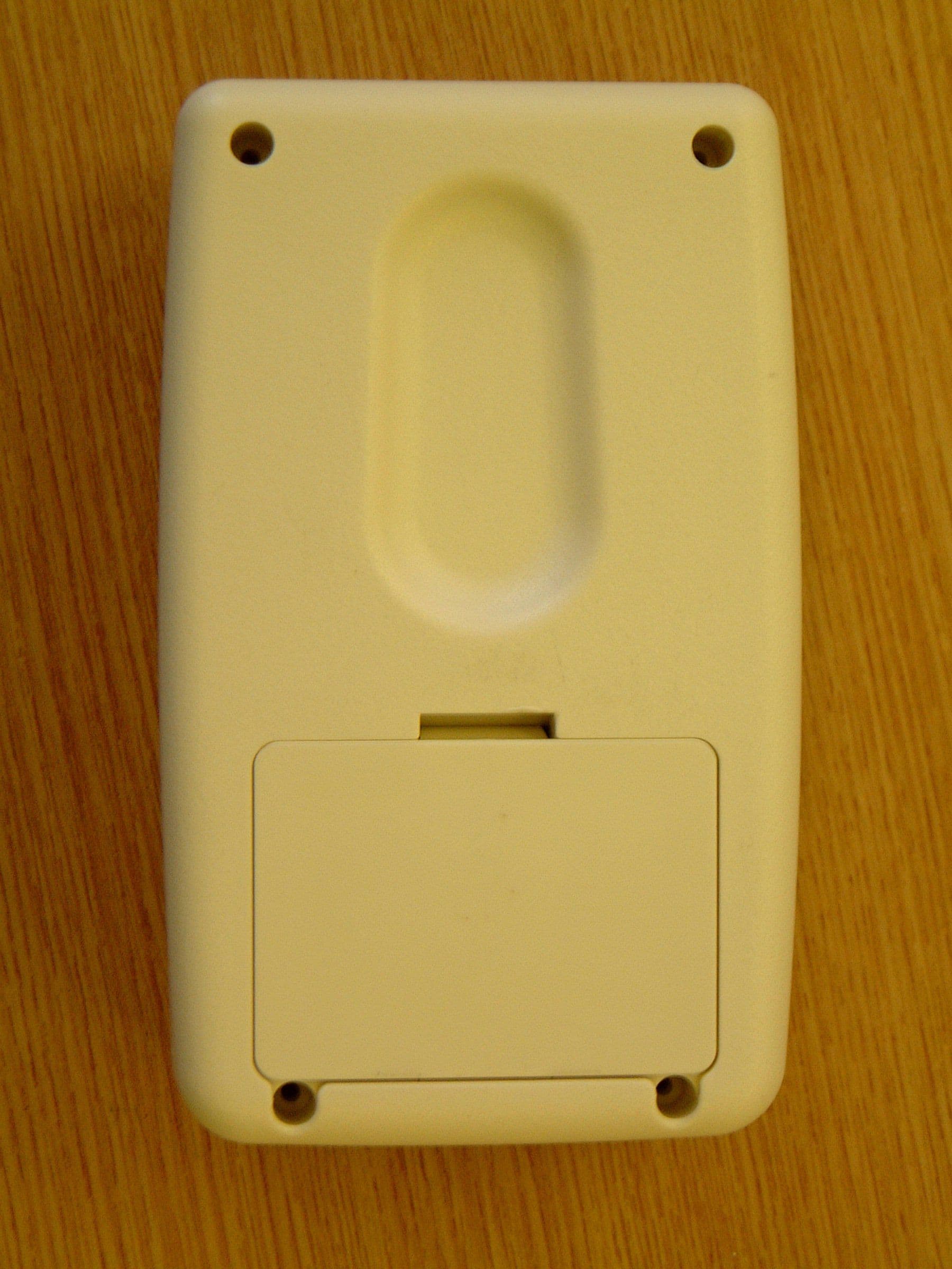
Click to zoom
Application Details
- Equipment Class
- DSC - Part 15 Security/Remote Control Transmitter
- Date of Grant
- Apr 11, 2005
- Application Purpose
- Original Equipment
- Date of Application
- Apr 11, 2005
- Equipment Note
- RF REMOTE CONTROL
- Frequency Range
- 433.92000000 - 433.92000000
- Country
- United Kingdom
Documents & Files
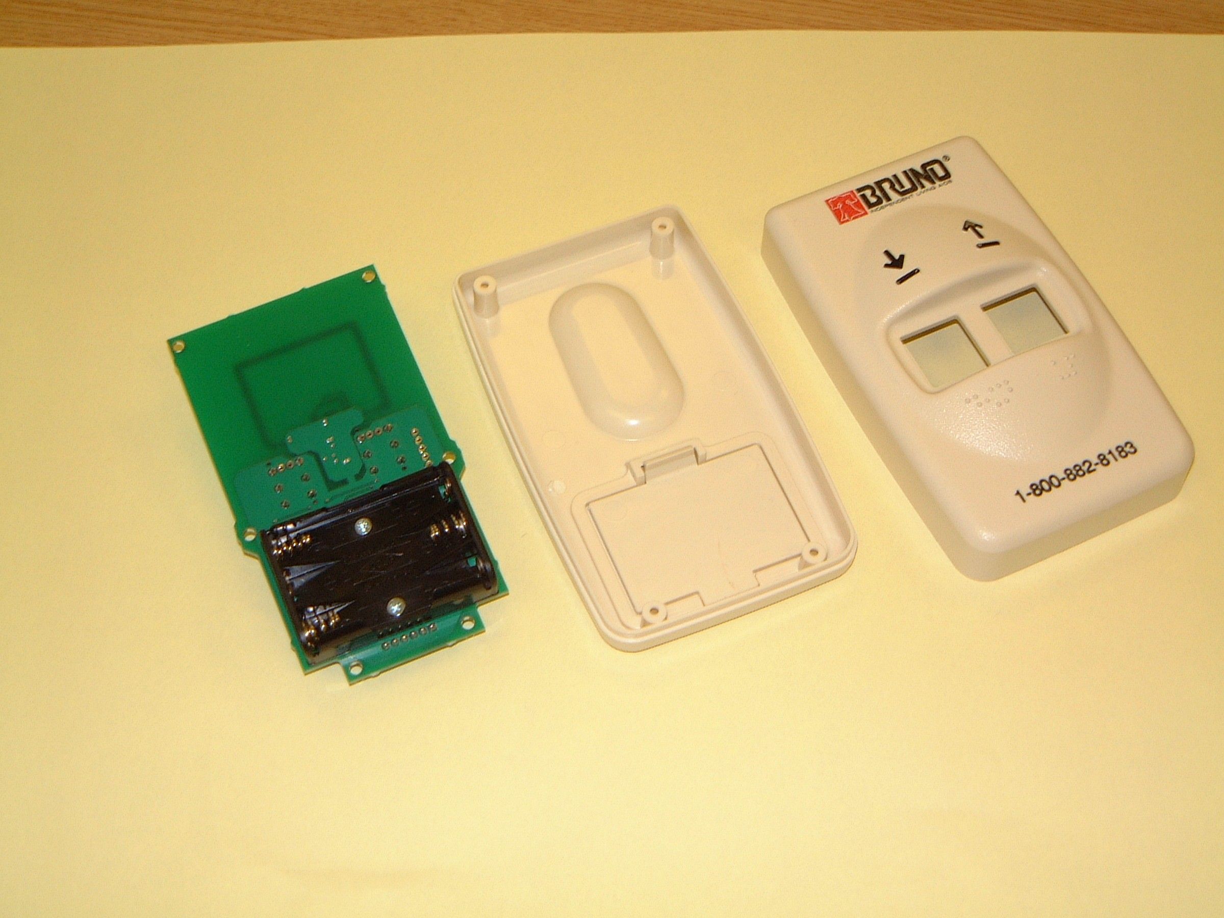
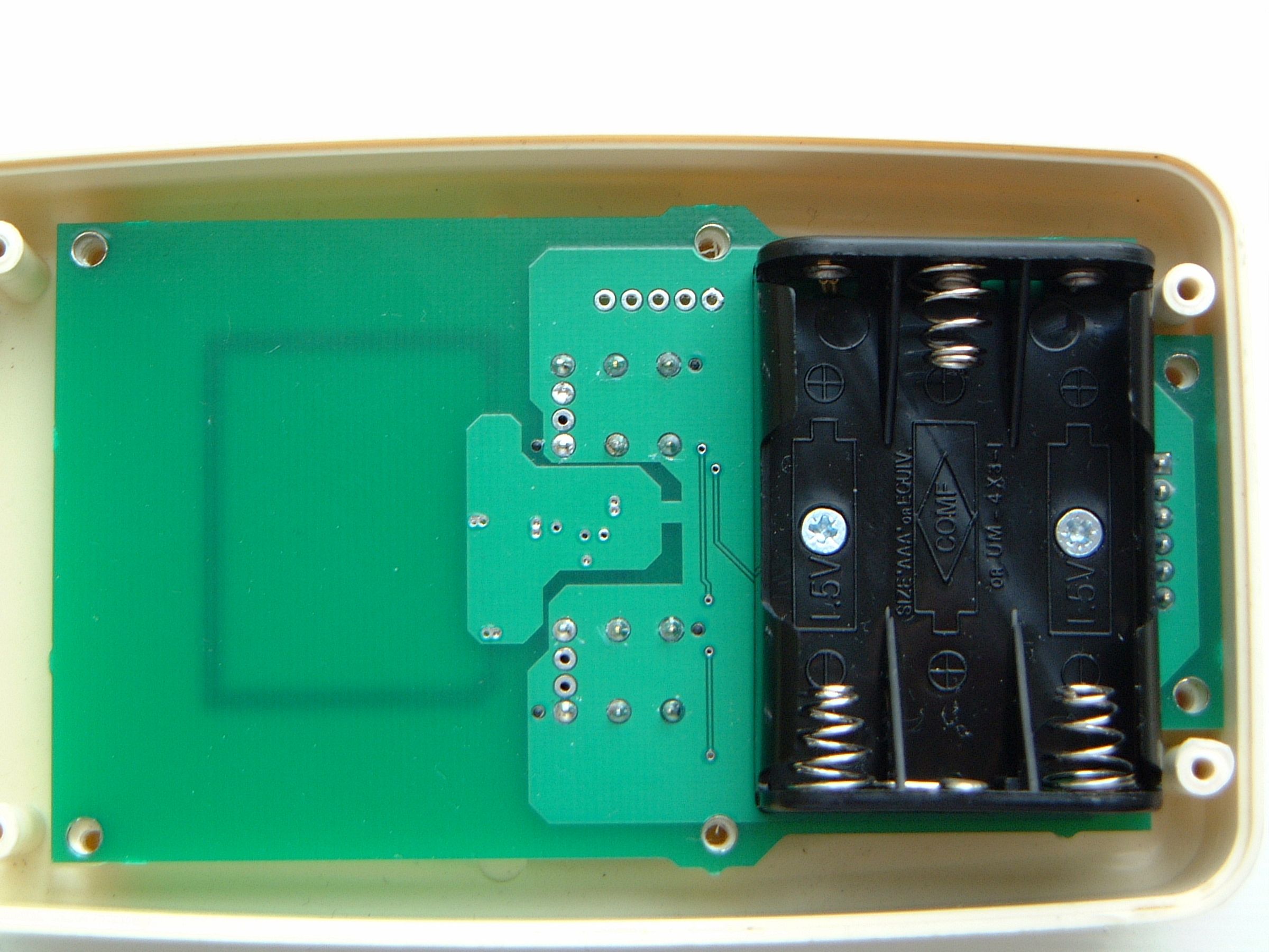
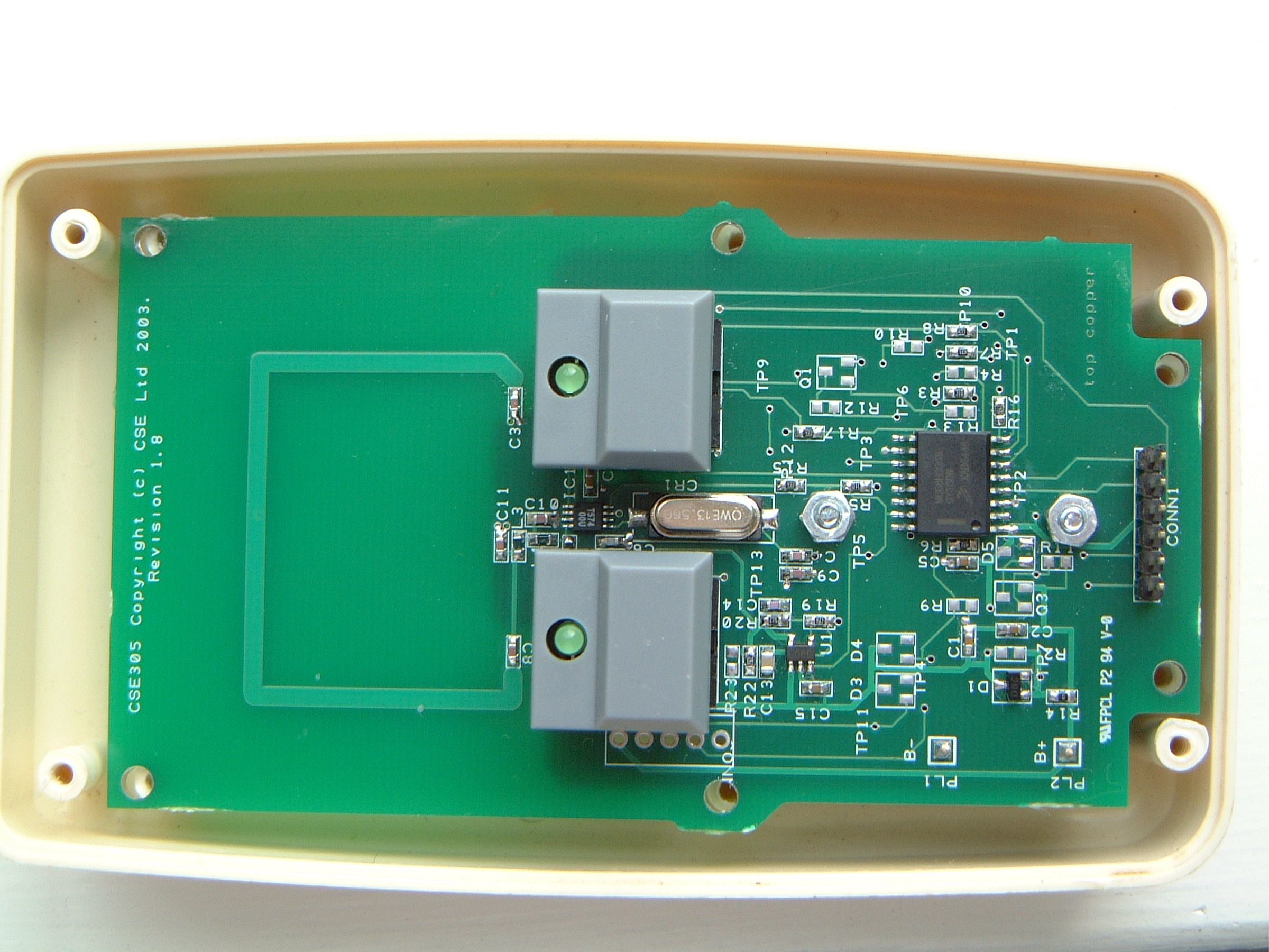
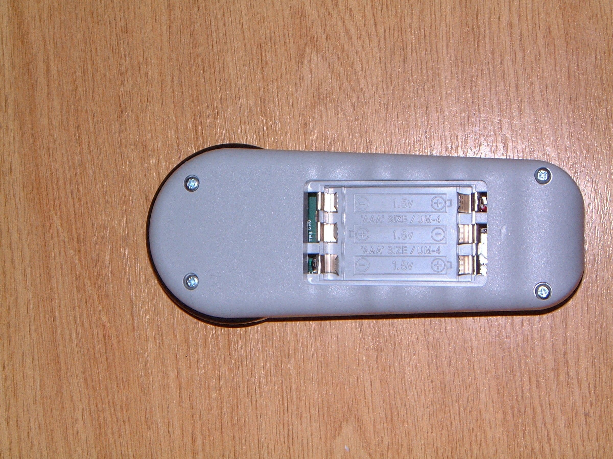
Document Text
Text extracted from the exhibit documents filed with the FCC. Open a document above to read the original.
Users Manual
1 ©2005,1998 Bruno Independent Living Aids, Inc.® CRE-2100 NRUL 04-04-2005 FCC REGULATIONS This equipment has been tested and found to comply with the limits for a Class B digital device, pursuant to Part 15 of the FCC rules. These limits are designed to provide reasonable protection against harmful interference in a residential installation. This equipment generates, uses, and can radiate radio frequency energy, and if not installed and used in accordance with the instructions, may cause harmful interference to radio communications. However, there is no guar - antee that interference will not occur in a particular installation. If this equip- ment does cause harmful interference to radio or television reception, which can be determined by turning the equipment off and on, the user is encouraged to try to correct the interference by one or more of the of the following mea - sures: •Reorient or relocate receiving antenna. •Increase separation between equipment and receiver. •Consult your dealer or an experienced radio/TV technician. THIS DEVICE COMPLIES WITH FCC RULES PART 15. OPERATION IS SUBJECT TO THE FOLLOWING TWO CONDITIONS: (1) THIS DEVICE MAY NOT CAUSE HARMFUL INTERFERENCE AND, (2) THIS DEVICE MUST ACCEPT INTERFERENCE THAT MAY BE RECEIVED, INCLUDING INTERFERENCE THAT MAY CAUSE UNDESIRED OPERATION. UNDERWRITERS LABORATORIES, INC. REGULATIONS: THIS ELEVATOR INSTALLATION IS TO BE COMPLETED BY QUALIFIED PERSONNEL ONLY. This lift is intended to be installed in accordance with the current editions of the U.S. National Electric Code NFPA-70 and the Standard for Platform Lifts and Stairway Chairlifts, ANSI/ASME A18.1-1999. REGULATORY INFORMATION 2 ©2005,1998 Bruno Independent Living Aids, Inc.® CRE-2100 NRUL 04-04-2005 MOUNTING THE STANDARD CALL/SEND TRANSMITTER Two mounting possibilities exist for the standard call/send transmitter: 1. Velcro ® 2. bracket. The Velcro® strips as well as the bracket and mounting hardware are provided. Mounting with Velcro® strips: 1. Determine the mounting location. 2. Peel off the backing on the Velcro® strips and attach one half of the strip to the mounting location and the mating half to the back of the transmitter. 3. To mount the transmitter, gently press the Velcro® strip on the transmitter against the mating strip on the mounting location. Mounting with bracket and hardware: 1. Mount the bracket to the back of the transmitter using the (4) screws provided. 2. Position the bracket/transmitter unit in the mounting location on the wall and mark the top and bottom bracket holes. 3. Drill a pilot hole slightly smaller than the anchors provided. 4. Gently pound the anchors into the wall with a rubber mallet. 5. Position the bracket/transmitter unit on the wall so that the top/bottom bracket holes align with the anchors. 6. Secure the bracket/transmitter to the wall using the screws provided. standard transmitter mounted with Velcro® standard transmitter mounted with bracket INSTALLATION 3 ©2005,1998 Bruno Independent Living Aids, Inc.® CRE-2100 NRUL 04-04-2005 MOUNTING THE COMMERCIAL CALL/SEND TRANSMITTER commercial call/send transmitter 1. Install the key-controlled call/send transmitters as shown below. 2. The distan ce between the key switch and the floor should measure approximately 48”. 3. Install one tr ansmitter at the top of the stairs, and one at the bottom. NOTE: Codes may vary from one municipality to another. Check pertinent local codes in force before beginning installation of the call/send transmitter. INSTALLATION 4 ©2005,1998 Bruno Independent Living Aids, Inc.® CRE-2100 NRUL 04-04-2005 TESTING THE CALL/SEND TRANSMITTER 1. Using the rocker switch on the seat arm - rest, run the unit up and down the rail. NOTE: The unit should travel noticeably faster going up than down. 2. Check for smooth operation and travel. 3. Now, using one of the remote call/send transmitters, run the unit up and down the rail. 4. Repeat Step 3 with the other transmitter. 5. Check for smooth operation and travel. Soft Start Feature The controller includes a soft start feature which causes a short delay between the time the rocker switch on the armrest is depressed and the initiation of carriage movement. This is normal! TESTING THE UNIT COMPONENTS 1. When the installation is complete, test the operation of the following components: a. rocker switch b. footrest safety switches c. carriage limit switches d. seat safety switch. CUSTOMER EDUCATION Before leaving the installation site, be sure that the customer fully understands the correct and safe operation of the Stairway Elevator. Have the customer operate the unit while you are there to answer any questions or concerns. Remind the customer to always use the seat positioning belt. NOTE: This unit includes equipment covered by FCC regulations. Any changes or modifications to the call/send transmitter or re - ceiver, unless expressly approved by Bruno Independent Liv- ing Aids, Inc.® (the party responsible for ensuring its equip- ment complies with FCC regulations), could void the user’s authority to operate the equipment. INSTALLATION 5 ©2005,1998 Bruno Independent Living Aids, Inc.® CRE-2100 NRUL 04-04-2005 circuit board learn/erase LED switch (S4) LEARNING THE CALL/SEND TRANSMITTER The (2) remote call/send transmitters shipped with the unit have been “learned” in the fac - tory. No adjustment is required. Should you need to add or replace a remote, you will have to “learn” that remote. To do so, follow the instructions below. Learning a remote call/send transmitter 1. On the circuit board, locate the Learn/Erase switch (S4) and its LED. Please refer to the illustration in the lower left corner. 2. While holding down switch (S4) on the circuit board (Learn/Erase LED is on), press the UP or DOWN button on the transmitter until the circuit board LED goes out (approx. 2 to 5 seconds). Release S4 and the transmitter button. The remote is now “learned”. 3. Repeat Steps 1 and 2 for any other remote call/send transmitter(s) t…
Text truncated - open the document above for the full version.
Block Diagram
Controlled Speed Engineering Ltd FCC ID: SZBCSE305 Transmitter Block Diagram Down up PCB Loop Antenna EEPROM Low Battery Detector T5754 RF Output Device 8 – BIT Microprocessor Remote Key Switch 2v Regulator Preliminary Specification ¾ Carrier Frequency 433MHz ¾ Operational Voltage: 4.5 ~ 2.7volts ¾ Current Consumption: <20mA (peak) ¾ Sleep Mode Current: < 10uA ¾ Antenna:2mm x 25mm x 34mm PCB loop ¾ Baud Rate: 1000bps ¾ Modulation Format: Return to Zero Frequency Shift Keying (FSK) ¾ Frequency Stability: +/- 100Hz
Cover Letter(s)
ΑΒΧ∆ΕΦ BS EN ISO 9001:2001 approved Timco Engineering Inc. Our ref: CSEFCC002 FRN N 0 : 0012636486 Grantee Code: SZBCSE305 Dear sir With regard to our application for FCC compatibility under CFR 47 : 2004 Code of Federal Regulations: Pt 15 Subpart C – Radio Frequency Devices-International Radiators. I am applying for PERMANENT confidentiality for the CSE305 radio remote control for the following : 1 The design schematics. 2 PCB layout This application has been presented in support of the above design, we feel the design overcomes the power output requirements of the FCC regulations in a unique design combination of PCB layout and electronic design, and therefore wish to maintain our right to confidentiality thus protecting our design from publication in the public domain. Yours faithfully A. Fielden Quality Manager / Senior Development Engineer Controlled Speed Engineering Ltd St Pegs House Beck Lane, Brighouse, West Yorkshire, HD6 4AH Telephone: (01484) 721981 Fax: (01484) 721984 E-mail: [email protected] WWW,controlledspeed.co.uk VAT Registration No.763 9579 71 Registered in England No. 2711409
Cover Letter(s)
LOW POWER Tx 15.231 for CERTIFICATION Code: DSC (Tx) APPLICANT: CONTROLLED SPEED ENGINEERING LTD. Job #: 621UC5 Customer’s Name: CONTROLLED SPEED ENGINEERING LTD. Contact Name: ANTHONYFIELDENQUALITY MANAGER Contact Phone: -148-440-4107 Contact Fax: -148-472-1984 Contact Email: [email protected] Equipment Description: RF REMOTE CONTROL FCC Id: SZBCSE305 Model #: CSE305 Company # & UPN: -CSE305 Rule Section : 15.231 Scope: A1 Composite device? ______Modular Approval? ______ RSS 210 6.1 Center frequency of the lowest channel to the highest channel. Confidential request per Section 0.459 ______ NA FOR CANADA Class II permissive change statement? _________ Do the changes require a new application?. REQUIRED EXHIBIT FILENAME TO USE 731 form filled out (You can download form from our web site) (model)731Form ___OK___ FCC ID label sample (model)LabelSmpl ___X___ FCC ID label location information (model)LabelLoc ___X___ External Photos, preferably in pdf format as one file, page 1 & 2 etc. (model)ExtPho ___X___ Internal Photos, preferably in pdf format, as above (model)IntPho ___X___ Test set-up photos (model)Tsup ___X___ Operational Description (model)OpDes ___X___ Block diagrams (model)BlkDia ___X___ Schematics (model)Schem ___OK___ Test Report in MS-Word, ASCII or PDF format (model)TestRpt ___X___ Users Manual, preferably in MS Word or PDF format (model)UserMan ___X___ Parts List, if applicable (model)PartsLst ______ IC- Cover Letter (model)CoverLetter ______ IC- Annex I (model)Annex I ______ IC- Annex II (model)Annex II ______ Acknowledgement of IC Listing Requirements ______ Canadian Maintenance Facility Name Contact Name Address Phone number Email ______ SCOPE OF WORK Description of Test Standard Comments NEEDED Radiated Emission ANSI C63.4-2000 1 Place for up to 1MHz 2 Places up to 10MHz 3 places of over 10MHz X Power Line Conducted ANSI C63.4-2000 or RSS 212- 5.0 IC only requires down to 450kHz. X Occupied Bandwidth ANSI C63.4-2000-0.25% RSS 210 6.1.1(c) In addition to the 0.25% BW we need the 20dB BW for the emission designator X Duty Cycle Pulses X Requirements: Periodic operation except as specified in Section 15.231(e). Transmission of a control signal only. Toys are not permitted. Continuous transmission such as voice and, video not permitted. Data transmissions are permitted, as long as it is sent with a control signal. Recognition codes for sensor identification allowed. 5 second transmission limitation. Manual transmission must deactivate 5 seconds after release. Automatic transmissions must cease 5 seconds after activation. 5 second transmission limitation exceptions. Transmissions at regular predetermined intervals are not permitted. Polling or supervision transmissions to determine system integrity of transmitters used in security or safety applications are allowed if the periodic rate of transmission does not exceed one transmission of not more than one second duration per hour for each transmitter. *** Transmissions with a non-predetermined(random) delay time every few seconds are not allowed. Transmissions during emergencies involving fire, security, and safety of life, when activated to signal an alarm, may operate during the pendency of the alarm condition. Fundamental and spurious limits are listed in the table of Section 15.231(b). Average limit or alternatively Quasi peak. Spurious limit is 20 dB below the fundamental limit. Frequency tolerance requirement for devices in 40.66-40.70 MHz. Continuous transmissions during non safety of life conditions are not permitted. e.g. Asset protection is not considered a Safety of life Condition Toggle switches that lock the button in the on position and causes transmission greater than 5 seconds is prohibited. Common in Crane controllers. Data transmission prohibited. Transmission of temperature, pressure and elapsed time are considered data and are not allowed. Section 2.1033: ______ A copy of the installation and operating instruction to be furnished the user. User information? Should be read for consistency. (6)A description of the Tx’d signal, ie: Control, FM, or Etc. ______ Duty Cycle: Was duty cycle cal. Correctly. See FCC Procedure __ok____ FCC 15.19: label requirements: Example shown below. need (Country of Origin) FCC ID: _____________ THIS DEVICE COMPLIES WITH PART 15 OF THE FCC RULES. OPERATION IS SUBJECT TO THE FOLLOWING TWO CONDITIONS: (1) THIS DEVICE MAY NOT CAUSE HARMFUL INTERFERENCE, AND (2) THIS DEVICE MUST ACCEPT ANY INTERFERENCE RECEIVED, INCLUDING INTERFERENCE THAT MAY CAUSE UNDESIRED OPERATION. *NOTE: If the device is too small for the 2 part warning to fit, then it must be placed in the user’s manual. Section 15.21 INFORMATION TO USER: THE USER’S MANUAL OR INSTRUCTION MANUAL FOR AN INTENTIONAL OR UNINTENTIONAL RADIATOR SHALL CAUTION THE USER THAT CHANGES OR MODIFICATIONS NOT EXPRESSLY APPROVED BY THE PARTY RESPONSIBLE FOR COMPLIANCE COULD VOID THE USER'S AUTHORITY TO OPERATE THE EQUIPMENT. A SAMPLE STATEMENT IS BELOW: ok NOTE: THE MANUFACTURER IS NOT RESPONSIBLE FOR ANY RADIO OR TV INTERFERENCE CAUSED BY UNAUTHORIZED MODIFICATIONS TO THIS EQUIP- MENT. SUCH MODIFICATIONS COULD VOID THE USER’S AUTHORITY TO OPERATE THE EQUIPMENT. IC- LABELLING: RSP100 & CB-03 take precedent over the equipment standard. RSP 100: 4. Labelling of Certified Radio Equipment: Certified radio equipment must be labelled with a unique certification/registration number, which consists of the Company Number (CN), assigned by the Bureau, followed by the Unique Product Number (UPN), assigned by the TAC or Certificate holder. The certification/registration number shall appear as follows: “IC: XXXXXX-YYYYYYYY” Where: • “XXXXXX-YYYYYYYY” is the certification/registration number; • “XXXXXX” is the Company Number (CN), made of at most 6 alphanumeric characters (A-Z, 0-9), assigned by Industry Canada; • “YYYYYYYY” is the Unique Product Number (UPN), made of at most 8 alphanumeric characters • The letters "IC" have no other meani…
Text truncated - open the document above for the full version.
ID Label/Location Info
FCC ID: SZBCSE305 BRUNO INDEPENDENT LIVING AIDS, INC. MODEL NO. SRE-00909A, SRE-00909AE THIS DEVICE COMPLIES WITH FCC RULES PART 15. OPERATIONIS SUBJECT TO THE FOLLOWING TWO CONDITIONS: (1) THISDEVICE MAY NOT CAUSE HARMFUL INTERFERENCE AND (2) THIS DEVICE MUST ACCEPT ANY INTERFERENCE THAT MAYBE RECEIVED, INCLUDING INTERFERENCE THAT MAY CAUSEUNDESIRED OPERATION. FCC I D: SZBCSE305 BRUNO I NDEPENDENT LIVING AI DS, INC. MODEL NO. SRE-00909A, SRE-00909AE THI S DEVI CE COMPLIES WI TH FCC RULES PART 15. OPERATIONI S SUBJ ECT TO THE FOLLO WI NG TWO CONDI TI ONS: (1) THISDEVI CE MAY NO T CAUSE HARMFUL INTERFERENCE AND (2) THI S DEVI CE MUST ACCEPT ANY INTERFERENCE THAT MAYBE RECEI VED, I NCLUDI NG I NTERFERENCE THAT MAY CAUSEUNDESIRED O PERATI ON. DOWN UP OFF ON
Operational Description
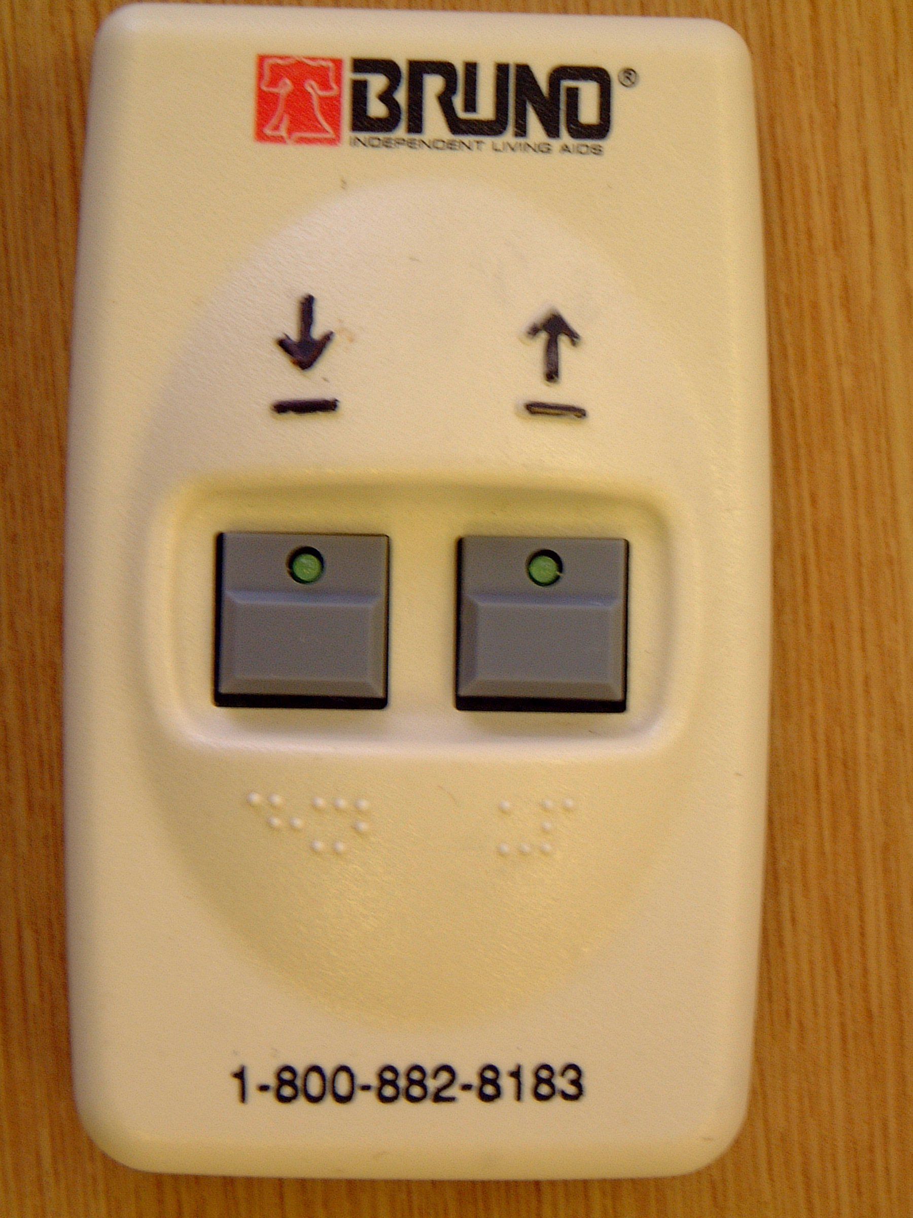
OPERATIONAL DESCRIPTION Controlled Speed Engineering Ltd FCC ID: SZBCSE305 ________________________________________________________________ The CSE305 is a hand held battery powered transmitter designed to remote control a stairlift. The user activates it by means of push buttons. The CSE305 transmits a wideband FM modulated data stream with approximately +/- 25kHz deviation on a nominal 433.92MHz carrier with a baud rate of 1Kbit/sec. It uses an inbuilt printed loop antenna. Of PCB dimension 2mm track width, 26mm X 34mm rectangle. The data sent is produced by a microprocessor and contains an individual code for each transmitter. It commands the stairlift to go up or down or stop. The data pulse stream is a block of 60 bits for 60 mS followed by a pause of no transmission for 40 mS . This sequence is repeated while the user presses the activating button. See Block diagram. U:\C\CONTROLLED_SZB\621UC5\operational description.doc Rev. 1/1/03
Test Report
|---------- ( Cambridge Ltd. ) ----------| Testing EMCEMC Consultancy EMC Training or : 01223 241140 (accounts) 23, Headington Drive, Cambridge. CB1 9HE Tel : 01954 251974 (test site) Fax : 01954 251907 email: [email protected] web : www.dbtechnology.co.uk REPORT ON ELECTROMAGNETIC COMPATIBILITY TESTS Performed at: TWENTY PENCE TEST SITE Twenty Pence Road, Cottenham, Cambridge U.K. CB4 8PS on Controlled Speed Engineering CSE305 dated 28 January 2005 Document History Initial release03/02/051 Approved by Revised by Description of modifications Affected page(s) DateIssue Based on report template: v031111 1 of 14 Page: Test Report T1351 Test No: FCC ID: SZBCSE305 R1988 1 Report No: Issue No: This report shall not be reproduced except in full, without the written approval of: dB Technology (Cambridge) Ltd. Equipment Under Test (EUT):CSE305 Test Commissioned by:Controlled Speed Engineering St Pegs House Thornhill Beck Lane Brighouse N. Yorkshire Representative:Alan Hurst Test Started:27 January 2005 Test Completed:27 January 2005 Test Engineer:Dave Smith Date of Report:28 January 2005 Report: Written by:Dave SmithChecked by:Derek Barlow Signature:Signature: Date:28th January 2005Date:3rd February 2005 dB Technology can only report on the specific unit(s) tested at its site. The responsibility for extrapolating this data to a product line lies solely with the manufacturer. Test Standards Applied CFR 47 : 2004Code of Federal Regulations: Pt 15 Subpart C - Radio Frequency Devices - Intentional Radiators 2 of 14 Page: Test Report T1351 Test No: FCC ID: SZBCSE305 R1988 1 Report No: Issue No: This report shall not be reproduced except in full, without the written approval of: dB Technology (Cambridge) Ltd. Emissions Test Results Summary CFR 47 : 2004PASS TestPortMethodLimitPASS/FAILNotes Conductedac powerANSI C63.4:2001CISPR22(B)N/A#1 CISPR22(B) Emissions conducted Radiated ANSI C63.4:2001FCC(C)PASSFCC(C) Emissions radiated fcc_v040903 #1Test not applicable because EUT was battery powered and had no ac power port. 3 of 14 Page: Test Report T1351 Test No: FCC ID: SZBCSE305 R1988 1 Report No: Issue No: This report shall not be reproduced except in full, without the written approval of: dB Technology (Cambridge) Ltd. Contents 14 PLOT 4 Emission Bandwidth ............................................................. 13 PLOT 3 Duty Cycle ..................................................................... 12 PLOT 2 Radiated Emissions - 1GHz to 5GHz ................................................ 11 PLOT 1 Radiated Emissions - 25MHz to 1GHz ............................................... 104.2 Radiated Emissions Results - above 1GHz................................................ 94.1 Radiated Emissions Results - below 1GHz................................................. 8 4 Test Data ................................................................................ 83.2 Emissions Bandwidth.................................................................... 83.1 Radiated Emissions - Fundamental and Spurious........................................... 8 3 Tests ................................................................................... 7 2 Test Equipment .......................................................................... 6 Photograph 1 Arrangement of EUT .......................................................... 6 Figure 1 Arrangement of EUT .............................................................. 51.3 EUT Operating Modes................................................................... 51.2 Modifications to EUT.................................................................... 51.1 General................................................................................ 5 1 EUT Details ............................................................................. 4 of 14 Page: Test Report T1351 Test No: FCC ID: SZBCSE305 R1988 1 Report No: Issue No: This report shall not be reproduced except in full, without the written approval of: dB Technology (Cambridge) Ltd. 1 EUT Details 1.1 General The EUT was a CSE305 remote control unit for a stair lift. The unit is an intentional transmitter operating at 433.9MHz. The transmitter operation is periodic and intended to operate under the provisions of CFR 47 part 15.231. The unit was battery powered and had no ports for the connection of external cables. Details of the EUT are listed below. ItemManufacturerModelDescriptionSerial No:Notes CSECSE305EUT 1.2 Modifications to EUT Details of any modifications that were required to achieve compliance are listed below. The modification numbers are referred to in the results sections as appropriate. ModDetailsImplemented for No: 1 Resistor value changed to reduce carrier level.Harmonic levels 1.3 EUT Operating Modes The EUT was tested in the following operating mode or modes. Generally, operating modes are chosen that will exercise the functions of the EUT as fully as possible and in a manner likely to produce maximum emission levels or susceptibility. Individual test result sheets reference the operating mode of the EUT. OperatingDetails Mode 1 Button held down to produce continuous transmissions. 5 of 14 Page: Test Report T1351 Test No: FCC ID: SZBCSE305 R1988 1 Report No: Issue No: This report shall not be reproduced except in full, without the written approval of: dB Technology (Cambridge) Ltd. Figure 1 Arrangement of EUT EUT had no ports for connection to external cables. Photograph 1 Arrangement of EUT 6 of 14 Page: Test Report T1351 Test No: FCC ID: SZBCSE305 R1988 1 Report No: Issue No: This report shall not be reproduced except in full, without the written approval of: dB Technology (Cambridge) Ltd. 2 Test Equipment The test equipment used during the tests was one or more of the items listed below. Individual test result sheets indicate which items were used. Ref No:DetailsSerial Number A12Chase Bilog CBL6111A1012 A5Chase Bilog CBL6111A1760 A8EMCO 3115 DR Guide6070 PRE3dB Tech 100M-20G 36d…
Text truncated - open the document above for the full version.
Test Setup Photos
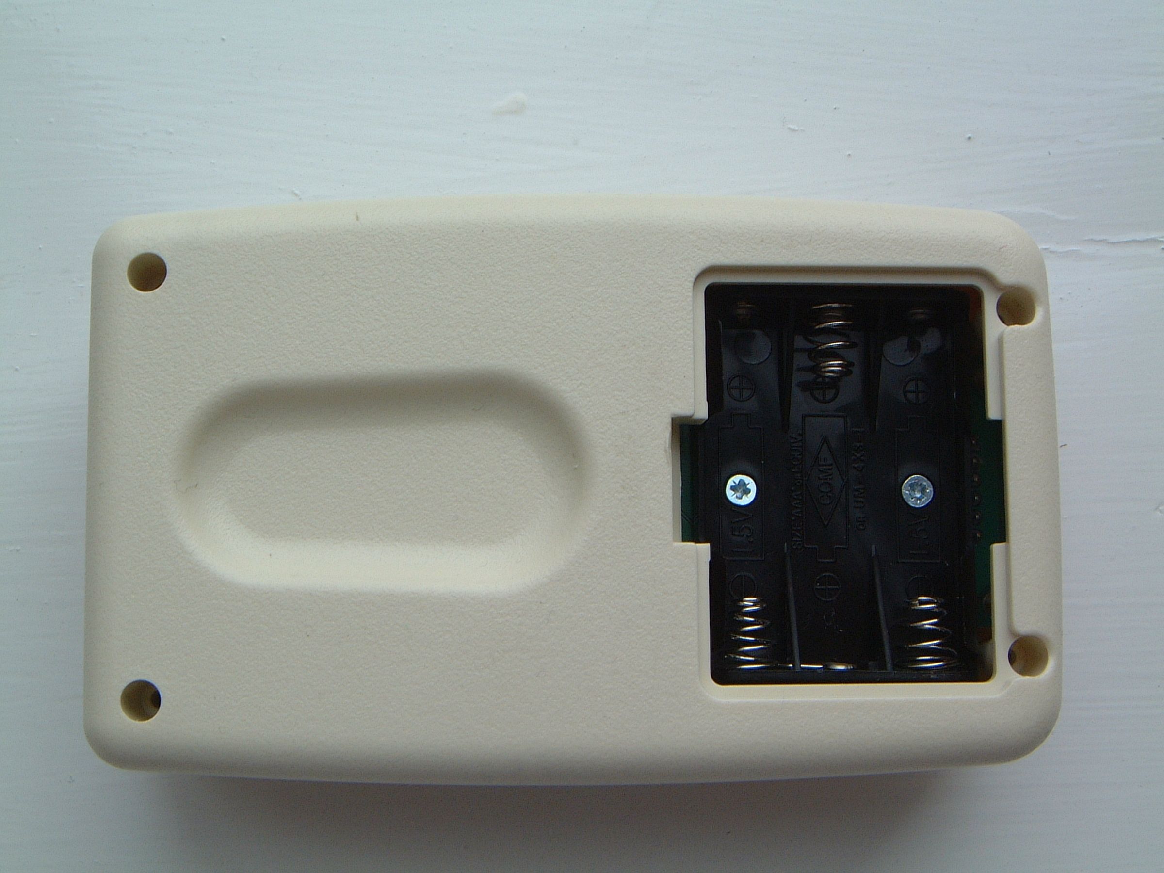
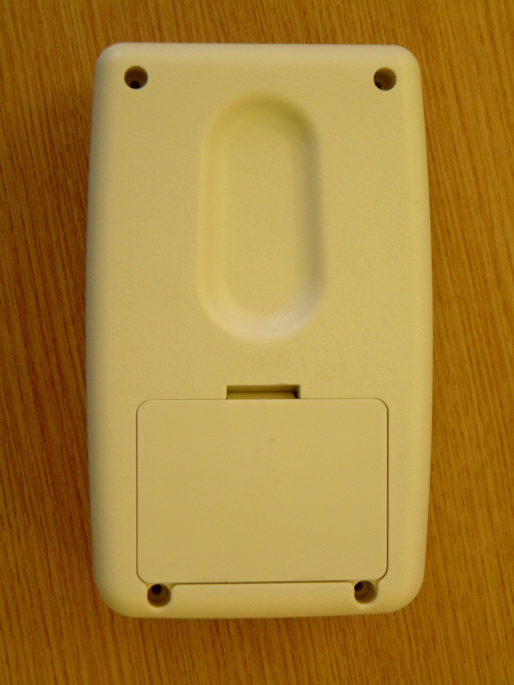
Figure 1 Arrangement of EUT EUT had no ports for connection to external cables. Photograph 1 Arrangement of EUT 6 of 14 Page: Test Report T1351 Test No: FCC ID: SZBCSE305 R1988 1 Report No: Issue No: This report shall not be reproduced except in full, without the written approval of: dB Technology (Cambridge) Ltd.
Contact Information
Applicant
Lucas Richard Bigham(Technical Manager)
Test Firm
DB TechnologyDave Smith
Technical Specifications
| # | Rule Parts | Frequency Range | Power Output |
|---|---|---|---|
| 1 | 15.231 | 433.92 MHz - 433.92 MHz | - |
Other Applications from Controlled Speed Engineering Ltd
SZBCSE035
Jun 29, 2005RF REMOTE CONTROL
Equipment Class
DSC - Part 15 Security/Remote Control Transmitter