T24-RLR13Remote Control
Holtzbrinck Publishers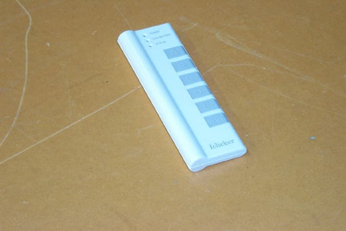
Click to zoom
Application Details
- Equipment Class
- DTS - Digital Transmission System
- Date of Grant
- Jun 04, 2006
- Application Purpose
- Original Equipment
- Date of Application
- Jun 01, 2006
- Equipment Note
- Remote Control
- Frequency Range
- 905.50000000 - 923.00000000
- Company
- Holtzbrinck Publishers
- Country
- United States
Documents & Files
Document Text
Text extracted from the exhibit documents filed with the FCC. Open a document above to read the original.
Users Manual
i>clicker Remote FCC Changes or modifications not expressly approved by Holtzbrinck Publishers could void the user's authority to operate this equipment. This device complies with part 15 of the FCC Rules. Operation is subject to the following two conditions: (1) This device may not cause harmful interference, and (2) this device must accept any interference received, including interference that may cause undesired operation. FCC ID: T24-RLR13 Note: This equipment has been tested and found to comply with the limits for a Class B digital device, pursuant to part 15 of the FCC Rules. These limits are designed to provide reasonable protection against harmful interference in a residential installation. This equipment generates, uses and can radiate radio frequency energy and, if not installed and used in accordance with the instructions, may cause harmful interference to radio communications. However, there is no guarantee that interference will not occur in a particular installation. If this equipment does cause harmful interference to radio or television reception, which can be determined by turning the equipment off and on, the user is encouraged to try to correct the interference by one or more of the following measures: —Reorient or relocate the receiving antenna. —Increase the separation between the equipment and receiver. —Connect the equipment into an outlet on a circuit different from that to which the receiver is connected. —Consult the dealer or an experienced radio/TV technician for help. i>clicker Remote IC IC: 6495A-RLR13 i>clicker Remote Instructions POWER Solid blue light = Your i>clicker is on. VOTE STATUS Green = Vote received and confirmed. Red flashing = Vote not received or your instructor has not begun polling; please try again. LOW BATTERY A flashing red light indicates that less than 10 hours of battery power remain. Press key in slot on back of your remote to release battery cover and replace 3 AAA batteries. Your remote will shut off automatically after 90 minutes. REGISTRATION Your unique remote ID is located on the sticker below. CHANGE FREQUENCY Press and hold ON/OFF button until power light flashes. Enter 2-key frequency code provided by your instructor.
Users Manual
i>clicker Remote FCC Changes or modifications not expressly approved by Holtzbrinck Publishers could void the user's authority to operate this equipment. This device complies with part 15 of the FCC Rules. Operation is subject to the following two conditions: (1) This device may not cause harmful interference, and (2) this device must accept any interference received, including interference that may cause undesired operation. FCC ID: T24-RLR13 Declaration of Conformity: Note: This equipment has been tested and found to comply with the limits for a Class B digital device, pursuant to part 15 of the FCC Rules. These limits are designed to provide reasonable protection against harmful interference in a residential installation. This equipment generates, uses and can radiate radio frequency energy and, if not installed and used in accordance with the instructions, may cause harmful interference to radio communications. However, there is no guarantee that interference will not occur in a particular installation. If this equipment does cause harmful interference to radio or television reception, which can be determined by turning the equipment off and on, the user is encouraged to try to correct the interference by one or more of the following measures: —Reorient or relocate the receiving antenna. —Increase the separation between the equipment and receiver. —Connect the equipment into an outlet on a circuit different from that to which the receiver is connected. —Consult the dealer or an experienced radio/TV technician for help. The antenna used for this transmitter must not be co-located or operating in conjunction with any other antenna or transmitter i>clicker Remote IC IC: 6495A-RLR13 i>clicker Remote Instructions POWER Solid blue light = Your i>clicker is on. VOTE STATUS Green = Vote received and confirmed. Red flashing = Vote not received or your instructor has not begun polling; please try again. LOW BATTERY A flashing red light indicates that less than 10 hours of battery power remain. Press key in slot on back of your remote to release battery cover and replace 3 AAA batteries. Your remote will shut off automatically after 90 minutes. REGISTRATION Your unique remote ID is located on the sticker below. CHANGE FREQUENCY Press and hold ON/OFF button until power light flashes. Enter 2-key frequency code provided by your instructor.
Attestation Statements
HOLTZBRINCK PUBLISHERS HOLTZBRINCK PUBLISHERS 41 Madison Avenue, New York, NY 10010 Tel: 212-576-9400 To whom it may concern: Holtzbrinck Publishers intends to market this product consistent with all exhibits provided for review to date. The principle source for the information to the user beyond the packaging, provided as an exhibit) will be the product website www.iclicker.com We acknowledge that any change in this violates the terms of our FCC Grant of Certification for the product (FCC ID:T24-RLR13). Thank you for your attention to this matter. Lawrence Jankovic Vice President
Cover Letter(s)
HOLTZBRINCK PUBLISHERS HOLTZBRINCK PUBLISHERS 41 Madison Avenue, New York, NY 10010 Tel: 212-576-9400 Letter Of Agency Thursday, May 11, 2006 American Telecommunications Certification Body, Inc. 6731 Whittier Avenue Suite C110 McLean, VA 22101 To Whom It May Concern: Please be advised that Holtzbrinck Publishers authorizes NCEE Labs to act on our behalf, until otherwise notified, for applications submitted to American Telecommunications Certification Body, Inc. (ATCB). We certify that we are not subject to denial of federal benefits that includes FCC benefits, pursuant to Section 5301 of the Anti-Drug Abuse ACT of 1988, U.S.C. 862. Further, no party, as defined in 47 CFR 1.2002(b), to the application is subject to denial of federal benefits, that includes FCC benefits. Thank you for your attention to this matter. Lawrence Jankovic Vice President
Cover Letter(s)
HOLTZBRINCK PUBLISHERS HOLTZBRINCK PUBLISHERS 41 Madison Avenue, New York, NY 10010 Tel: 212- 576- 9400 Request for Confidentiality Thursday, May 11, 2006 American Telecommunications Certification Body, Inc. 6731 Whittier Avenue Suite C110 McLean, VA 22101 RE: Certification Application FCC ID: T24-RLR13 and T24-TMX13 Please be advised that the following exhibits are being held confidential on behalf of Holtzbrinck Publishers: • Remote Block Diagram • Remote Schematic • Description of Circuit Functions for Remote The application contains technical information that Holtzbrinck Publishers deems to be trade secrets and proprietary. If made public, the information might be used to the disadvantage of the applicant in the market place. Thank you for your attention to this matter. Lawrence Jankovic Vice President
Cover Letter(s)
C M Y CM MY CY CMY K iclicker_package_back.pdf 5/29/06 12:37:13 PMiclicker_package_back.pdf 5/29/06 12:37:13 PM
External Photos
Figure 1 - EUT External View, Front Side Figure 2 - EUT External View, Back Side
ID Label/Location Info
25.4 mm NOTE: OUTLINE BORDERS ARE FOR ALIGNMENT/REGISTRATION ONLY AND SHOULD NOT BE PRINTED. TEXT COLOR: BLACK BACKGROUND COLOR: WHITE SCALE: 1/1 PROPRIETARY USE PURSUANT TO COMPANY INSTRUCTIONS TITLE: SCALE: ARTMASTER NO. REVISION: DATE:SHEET: C ALL RIGHTS RESERVED OF AS SHOWN 1 1 2 103M31 INSTRUCTION LABEL GRAPHICS 5/10/06 INSTRUCTIONS POWER Solid blue light = Your i>clicker is on. VOTE STATUS Green = Vote received and confirmed. Red flashing = Vote not received or your instructor has not begun polling; please try again. LOW BATTERY A flashing red light indicates that less than 10 hours of battery power remain. Press key in slot on back of your remote to release battery cover and replace 3 AAA batteries. Your remote will shut off automatically after 90 minutes. REGISTRATION Your unique remote ID is located on the sticker below. CHANGE FREQUENCY Press and hold ON/OFF button until power light flashes. Enter 2-key frequency code provided by your instructor. NEED HELP? www.iclicker.com 25.4 mm NOTE: OUTLINE BORDERS ARE FOR ALIGNMENT/REGISTRATION ONLY AND SHOULD NOT BE PRINTED. SCALE: 1/1 SCALE: 4/1 PROPRIETARY USE PURSUANT TO COMPANY INSTRUCTIONS TITLE: SCALE: ARTMASTER NO. REVISION: DATE:SHEET: C ALL RIGHTS RESERVED OF AS SHOWN 1 1 3 103M36 FCC GRAPHICS 5/15/06 This device complies with part 15 of the FCC rules. Operation is subject to the following two conditions: (1) This device may not cause harmful interference, and (2) This device must accept any interference received, including interference that may cause undesired operation. IC: 6495A-RLR13 FCC ID: T24-RLR13
Internal Photos
Figure 1 - EUT Internal Photo, Back Side Figure 2 - EUT Internal Photos, Back Side, Bottom Detail Figure 3 - EUT Internal Photo, Back Side, Top Detail Figure 4 - EUT Internal Photo, Front Side Figure 5 - EUT Internal Photo, Back Side, Bottom Detail Figure 6 - EUT Internal Photo, Back Side , Top Detail
RF Exposure Info
RF Exposure Statement 1. Standard Applicable According to 1.1307 (b)(1), systems operating under the provisions of this section shall be operated in a manner that ensure that the public is not exposed to radio frequency energy level in excess of the Commission’s guideline. This is a portable device. 2. Measurement Result: This a a portable/mobile device and the max peak output power is 14.6 dBm (.02884 W). Lower that low threshold 60/f GHz mW (28.84 mW), d<2.5 cm general population category. The SAR measurement is not necessary.
Test Report
EMC Test Report Company: Holtzbrinck Publishers 41 Madison Ave. New York, NY 10010 Contact: Lawrence Jankovic Product: i>clicker remote FCC ID: T24-RLR13 IC: 6495A-RLR13 Test Report No: R032806-01-01 APPROVED BY: Doug Kramer _________________________ Senior Test Engineer DATE: 19 May 2006 Total Pages: 45 The Nebraska Center for Excellence in Electronics (NCEE) authorizes the above named company to reproduce this report provided it is reproduced in its entirety for use by the company’s employees only. Any use that a third party makes of this report, or any reliance on or decisions made based on it, are the responsibility of such third parties. NCEE accepts no responsibility for damages, if any, suffered by any third party as a result of decisions made or actions based on this report. This report applies only to the items tested. NCEE is a FCC and Industry Canada registered lab. FCC #100875, IC #4294 NCEE Labs R032806-01-01 FCC ID: T24-RLR13 IC: 6495A-RLR13 Page 2 of 45 1.0 Summary of test results 1.1 Test Results 1.2 Test Methods 1.2.1 Conducted Emissions 1.2.2 Radiated Emissions 2.0 Description 2.1 Equipment under test 2.2 Laboratory description 2.3 Description of test modes 2.4 Applied standards 2.5 Description of support units 2.6 Configuration of system under test 3.0 Test equipment used 4.0 Detailed Results 4.1 Unique antenna requirement 4.2 Radiated emissions 4.3 Bandwidth 4.4 Maximum peak output power 4.5 Power spectral density 4.6 Bandedges Appendix A – Test photos Appendix B – Sample calculation Appendix C – RF exposure evaluation Appendix D – Table of figures NCEE Labs R032806-01-01 FCC ID: T24-RLR13 IC: 6495A-RLR13 Page 3 of 45 1.0 Summary of test results 1.1 Test Results The EUT has been tested according to the following specifications: APPLIED STANDARDS: FCC Part 15, Subpart C Standard Section Test Type and Limit Result Remark 15.203 Unique Antenna Requirement Pass PCB Antenna 15.209 Radiated Emission Pass Meets the requirement of the limit. 15.247(a)(2) Spectrum Bandwidth of a Direct Sequence Spread Spectrum System, Limit: Min. 500kHz Pass Meets the requirement of the limit. 15.247(b) Maximum Peak Output Power, Limit: Max. 30dBm Pass Meets the requirement of the limit. 15.247(c) Transmitter Radiated Emissions, Limit: Table 15.209 Pass Meets the requirement of the limit. 15.247(d) Power Spectral Density, Limit: Max. 8dBm Pass Meets the requirement of the limit. 15.247(c) Band Edge Measurement, Limit: 20dB less than the peak value of fundamental frequency Pass Meets the requirement of the limit. NCEE Labs R032806-01-01 FCC ID: T24-RLR13 IC: 6495A-RLR13 Page 4 of 45 1.2 Test Methods 1.2.1 Conducted Emissions The EUT was powered by 3 AAA batteries and had no connection to the public mains. Conducted emissions measurements were therefore not required on the EUT. 1.2.2 Radiated Emissions Compliance to CFR 47 Parts 15.209 and 15.247 was tested in accordance with the methods of ANSI/IEEE C63.4: 2003. Several configurations were examined and the results presented represent a worst-case scenario. The EUT was placed on a wooden table approximately 80cm high and centered on a 4m diameter turntable. The table was rotated to find the angles of maximum emissions and the receiving antenna was moved from 1m to 4m in both vertical and horizontal positions. The EUT was tested while sitting both vertically and horizontally. The horizontal configuration produced the highest emissions, and that position was used for all radiated testing. All measurements were taken at a distance of 3m from the EUT for Part 15.209 intentional radiator measurements, and 3m for 15.247 measurements of the fundamental frequency in the 902MHz to 928MHz band and subsequent harmonics. NCEE Labs R032806-01-01 FCC ID: T24-RLR13 IC: 6495A-RLR13 Page 5 of 45 2.0 Description 2.1 Equipment under test The Equipment Under Test (EUT) was a i>clicker remote, which is designed to communicate directly with the i>clicker base. The device allows students in a classroom to select an answer to multiple-choice questions and have their selected answer sent over a 900MHz wireless link to the i>clicker base located within the classroom. EUT Received Date: 26 April 2006 EUT Tested Date: 1 - 5 May, 2006 PRODUCT i>clicker Remote MODEL RLR13 POWER SUPPLY 3 AAA Batteries MODULATION TYPE FSK, 240 kHz peak deviation RADIO TECHNOLOGY Half-duplex RF Link TRANSFER RATE 152.34kb/s modulation rate 750 packets per second, maximum 0.4ms packet length FREQUENCY RANGE 905.5 MHz – 923 MHz NUMBER OF CHANNELS 16 MAXIMUM OUTPUT POWER 15 dBm, ANTENNA TYPE Internal, PCB mounted, ¼ wave 0 dBi gain DATA CABLE N/A I/O PORTS N/A ASSOCIATED DEVICES N/A NOTE: 1. For more detailed features description, please refer to the manufacturer's specifications or User's Manual. 2.2 Laboratory description All testing was performed at the NCEE Lincoln facility, which is a FCC and IC registered lab. This site has been fully described in previously submitted reports. Laboratory environmental conditions varied slightly throughout the tests: Relative humidity of 45 ± 4% Temperature of 20 ± 3° Celsius NCEE Labs R032806-01-01 FCC ID: T24-RLR13 IC: 6495A-RLR13 Page 6 of 45 2.3 Description of test modes Channel Frequency Channel Frequency AA 917.0 MHz CA 922.0 MHz AB 913.0 MHz CB 923.0 MHz AC 914.0 MHz CC 907.0 MHz AD 915.0 MHz CD 908.0 MHz BA 916.0 MHz DA 905.5 MHz BB 919.0 MHz DB 909.0 MHz BC 920.0 MHz DC 911.0 MHz BD 921.0 MHz DD 910.0 MHz NOTE: 1. Channel DA, AC and CB were chosen to represent frequencies at the lowest, middle and highest possible transmitting frequencies, respectively. 1. Below 1 GHz, channels DA, AC, and CB were tested individually 2. Above 1 GHz, channels DA, AC, and CB were tested individually. 2.4 Applied standards The EUT is a digital transmission device operating between 902 MHz and 928 MHz. According to the specifications of the manufacturer, it must comply with the requirements of the following standards: FCC Part 15, Subpart C. (15.247) using ANSI/IEEE C63.…
Text truncated - open the document above for the full version.
Test Setup Photos
NCEE Labs R032806-01-01 FCC ID: T24-RLR13 IC: 6495A-RLR13 Page 38 of 45 Figure 16 - Radiated Emissions Test Setup, EUT Vertical Figure 17 - Radiated Emissions Test Setup, EUT Horizontal (worst-case) NCEE Labs R032806-01-01 FCC ID: T24-RLR13 IC: 6495A-RLR13 Page 39 of 45 Figure 18 - Radiated Emissions Test Setup, EUT Horizontal (worst-case)
Contact Information
Applicant
Troy Williams(President)
Technical Contact
Nebraska Center for Excellence in ElectronicsDoug Kramer
[email protected]402-472-5880
4740 Discovery Dr. · Lincoln, Nebraska · United States
Test Firm
Nebraska Center for Excellence in ElectronicsNic Johnson
Technical Specifications
| # | Rule Parts | Frequency Range | Power Output |
|---|---|---|---|
| 1 | 15C | 905.5 MHz - 923 MHz | 29.00 mW |
Other Applications from Holtzbrinck Publishers
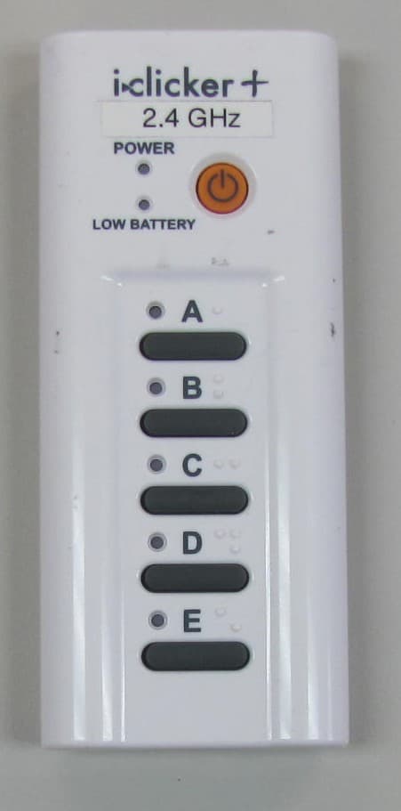
T24-ICL24
May 28, 20142.4 GHz i clicker Remote
Equipment Class
DXX - Part 15 Low Power Communication Device Transmitter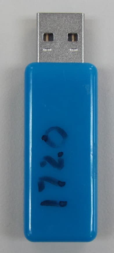
T24-ICL24B
May 28, 2014i clicker Base Unit
Equipment Class
DXX - Part 15 Low Power Communication Device Transmitter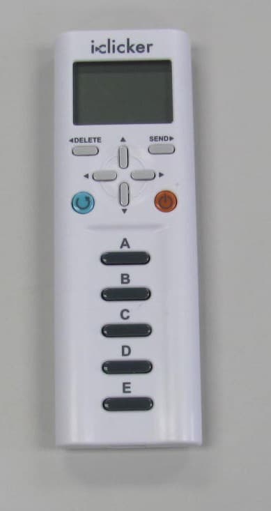
T24-RLR15
Aug 16, 2012Wireless handheld classroom response device for students
Equipment Class
DTS - Digital Transmission SystemT24-TMX14
Jan 11, 2011Wireless Audience Response Device
Equipment Class
DTS - Digital Transmission System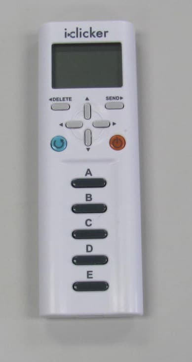
T24-RLR14
Sep 20, 2010Wireless audience response device
Equipment Class
DTS - Digital Transmission System