T24-TMX14Wireless Audience Response Device
Holtzbrinck PublishersApplication Details
- Equipment Class
- DTS - Digital Transmission System
- Date of Grant
- Jan 11, 2011
- Application Purpose
- Original Equipment
- Date of Application
- Jan 11, 2011
- Equipment Note
- Wireless Audience Response Device
- Frequency Range
- 903.50000000 - 923.00000000
- Company
- Holtzbrinck Publishers
- Country
- United States
Documents & Files
Document Text
Text extracted from the exhibit documents filed with the FCC. Open a document above to read the original.
Users Manual
Base Receiver 1 of 1 GETTING STARTED 1. Plug the USB cable (provided) into the port labeled “To Computer” on the side of the base. 2. Connect the USB cable to a USB port on your computer. 3. Plug the flash drive (provided) into the port labeled “Flash Memory” on the side of the base or into a USB port on your computer. 4. PC Users: From the Start menu, select Computer (or My Computer) and double click the flash drive. Mac Users: Double click the flash drive icon on your Desktop. 5. PC Users: Locate the i>clicker Win folder and open it. Mac Users: Locate the i>clicker Mac folder and open it. 6. Double-click the i>clicker program icon. Choose your course and click “Start Session.” 7. The i>clicker Session Toolbar appears in the top left corner of your computer screen. The toolbar floats over any presentation software. USING I>CLICKER IN CLASS 1. Click the Start button on the Session Toolbar to begin polling. Click the Stop button to stop polling. Note: The options on the Session Toolbar vary depending on the version of i>clicker software you use. 2. The base LCD displays the polling timer, the total vote count and the percentage of votes submitted for each answer choice. 3. Click the Results (Display) button on the Session Toolbar to view student results in the Results Chart. For more information about using i>clicker (including registration and i>grader), visit iclicker.com . CAUTION: Use only the approved power adapter: 5.0 Volts D.C.-1 Amp. To order an adapter, contact [email protected]. NOTE: This equipment has been tested and found to comply with the limits for a Class B digital device, pursuant to Part 15 of the FCC Rules. These limits are designed to provide reasonable protection against harmful interference in a residential installation. This equipment generates, uses and can radiate radio frequency energy and, if not installed and used in accordance with the instructions, may cause harmful interference to radio communications. However, there is no guarantee that interference will not occur in a particular installation. If this equipment does cause harmful interference to radio or television reception, which can be determined by turning the equipment off and on, the user is encouraged to try to correct the interference by one or more of the following measures: - Reorient or relocate the receiving antenna. - Increase the separation between the equipment and receiver. - Connect the equipment into an output on a circuit different from that to which the receiver is connected. - Consult the dealer or an experienced radio/TV technician for help. This product complies with FCC OET Bulletin 65 radiation exposure limits set forth for an uncontrolled environment.
ID Label/Location Info
Authorized Agent: Radiometrics Midwest Corporation (815) 293-0772 ID Label/Location Bottom of iClickr • • Size to be 100 x 65 millimeters Drawing of label
Test Report
Radiometrics Midwest Corporation - www.Radiomet.com Page 1 of 22 Electromagnetic Compatibility Test Report Tests Performed on a MacMillan Publishing, Inc. 900 MHz Transciever, i>clickr Model TMX14 Radiometrics Document RP-6895 Product Detail: FCC ID: T24-TMX14 IC: 6495A-TMX14 Equipment type: 900 MHz Digital transmission system. Test Standards: US CFR Title 47, Chapter I, FCC Part 15 Subpart C FCC Part 15 CFR Title 47: 2008 Industry Canada RSS-210, Issue 7: 2007 as required for Category I Equipment This report concerns: Original Grant for Certification FCC Part 15.247 Tests Performed For: Test Facility: MacMillan Publishing, Inc., Division of Holtzbrinck 41 Madison Av. 38 th Floor New York City, NY 10010 Radiometrics Midwest Corporation 12 East Devonwood Romeoville, IL 60446 (815) 293-0772 Test Date(s): (Month-Day-Year) October 3 thru November 9, 2010 Document RP-6895 Revisions: Rev. Issue Date Affected Pages Revised By 0 December 1, 2010 1 January 10, 2011 1, 4, 8, 9 & 20-22 Joseph Strzelecki Radiometrics Midwest Corporation www.radiomet.com Testing of the MacMillan Publishing, Inc., i>clickr Model TMX14, Transceiver, RP-6895 Rev. 1 Page 2 of 22 Table of Contents 1 ADMINISTRATIVE DATA.................................................................................................................... 3 2 TEST SUMMARY AND RESULTS......................................................................................................3 2.1 RF Exposure Compliance Requirements ..................................................................................... 4 3 EQUIPMENT UNDER TEST (EUT) DETAILS..................................................................................... 4 3.1 EUT Description............................................................................................................................ 4 3.1.1 FCC Section 15.203 & RSS-GEN Antenna Requirements .................................................... 4 3.2 Related Submittals........................................................................................................................ 4 4 TESTED SYSTEM DETAILS .............................................................................................................. 4 4.1 Tested System Configuration ....................................................................................................... 4 4.2 Special Accessories...................................................................................................................... 5 4.3 Equipment Modifications............................................................................................................... 5 5 TEST SPECIFICATIONS AND RELATED DOCUMENTS .................................................................. 5 6 RADIOMETRICS’ TEST FACILITIES.................................................................................................. 5 7 DEVIATIONS AND EXCLUSIONS FROM THE TEST SPECIFICATIONS ......................................... 6 8 CERTIFICATION ................................................................................................................................. 6 9 TEST EQUIPMENT TABLE ................................................................................................................ 6 10 TEST SECTIONS .............................................................................................................................. 7 10.1 AC Conducted Emissions ........................................................................................................... 7 Figure 1. Conducted Emissions Test Setup .................................................................................... 9 10.2 Occupied Bandwidth ................................................................................................................... 9 10.3 Peak Output Power................................................................................................................... 13 10.4 Power Spectral Density ............................................................................................................ 13 10.5 Band-edge Compliance of RF Conducted Emissions............................................................... 13 10.6 Spurious RF Conducted Emissions .......................................................................................... 15 10.7 Spurious Radiated Emissions ................................................................................................... 18 10.7.1 Radiated Emissions Field Strength Sample Calculation .................................................... 19 Figure 2. Drawing of Radiated Emissions Setup........................................................................... 19 10.7.2 Spurious Radiated Emissions Test Results ....................................................................... 19 10.7.3 Spurious Emissions (All Except Harmonics) ...................................................................... 20 10.7.4 Spurious Radiated Emissions Test Results above 1 GHz and Fundamental .................... 22 Notice: This report must not be reproduced (except in full) without the written approval of Radiometrics Midwest Corporation. Radiometrics Midwest Corporation www.radiomet.com Testing of the MacMillan Publishing, Inc., i>clickr Model TMX14, Transceiver, RP-6895 Rev. 1 Page 3 of 22 1 ADMINISTRATIVE DATA Equipment Under Test: A MacMillan Publishing, Inc., 900 MHz transceiver i>clickr Model: TMX14, Serial Number: none This will be referred to as the EUT in this Report Date EUT Received at Radiometrics: (Month-Day-Year) Test Date(s): (Month-Day-Year) October 1, 2010 October 3 thru November 9, 2010 Test Report Written By: Test Witnessed By: Joseph Strzelecki Radiometrics The tests were not witnessed by MacMillan Publishing, Inc. Radiometrics’ Personnel Responsible for Test: Test Report Approved By Joseph Strzelecki Senior EMC Engineer NARTE EMC-000877-NE Chris W. Carlson Director of Engin…
Text truncated - open the document above for the full version.
Test Setup Photos
Authorized Agent: Radiometrics Midwest Corporation (815) 293-0772 Test Setup Photographs Photographs of Radiated Emissions Test Setup Authorized Agent: Radiometrics Midwest Corporation (815) 293-0772 Photographs of Conducted Emissions Test Setup Authorized Agent: Radiometrics Midwest Corporation (815) 293-0772 Photograph of Antenna Conducted Emissions Test Setup
Contact Information
Applicant
Troy Williams(President)
Test Firm
Radiometrics Midwest Corp.Joseph Strzelecki
Technical Specifications
| # | Rule Parts | Frequency Range | Power Output |
|---|---|---|---|
| 1 | 15C | 903.5 MHz - 923 MHz | 21.00 mW |
Other Applications from Holtzbrinck Publishers
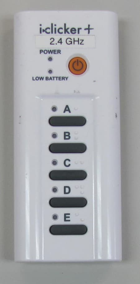
T24-ICL24
May 28, 20142.4 GHz i clicker Remote
Equipment Class
DXX - Part 15 Low Power Communication Device Transmitter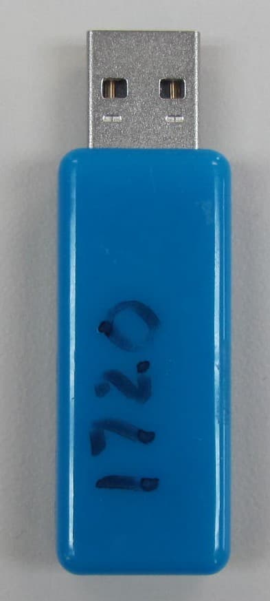
T24-ICL24B
May 28, 2014i clicker Base Unit
Equipment Class
DXX - Part 15 Low Power Communication Device Transmitter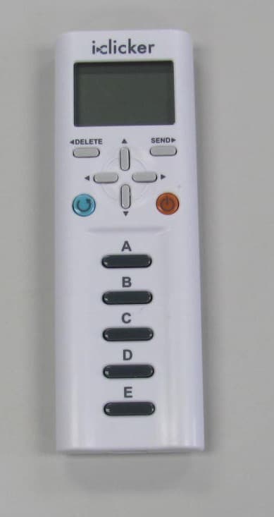
T24-RLR15
Aug 16, 2012Wireless handheld classroom response device for students
Equipment Class
DTS - Digital Transmission System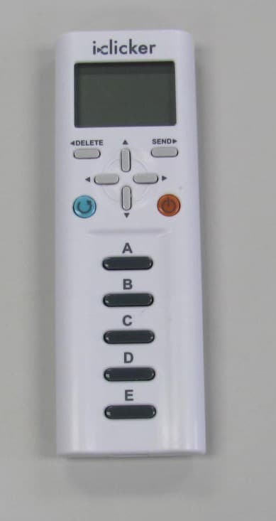
T24-RLR14
Sep 20, 2010Wireless audience response device
Equipment Class
DTS - Digital Transmission System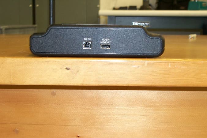
T24-TMX13
Jun 05, 2006Remote Control Base
Equipment Class
DTS - Digital Transmission System