T3G-WLP-1100F-000Outdoor Wireless LAN Access Point
Go Networks Inc.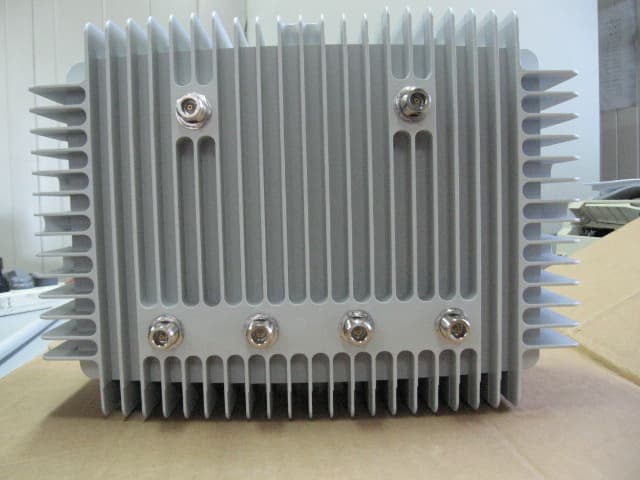
Click to zoom
Application Details
- Equipment Class
- DTS - Digital Transmission System
- Date of Grant
- Sep 24, 2006
- Application Purpose
- Original Equipment
- Date of Application
- Sep 24, 2006
- Equipment Note
- Outdoor Wireless LAN Access Point
- Frequency Range
- 5745.00000000 - 5825.00000000
- Company
- Go Networks Inc.
- Country
- United States
Documents & Files
Document Text
Text extracted from the exhibit documents filed with the FCC. Open a document above to read the original.
Users Manual
Document #: WLP22070601-R1 GO Metro Broadband Wireless Getting Started Technical Guide for WLP Wireless LAN Pico Base Station Version 2.2 GO WLP Getting Started Guide Trademarks and Licensing Agreement © 2006 GO Networks, Inc. All rights reserved. All information contained in this document is protected by international copyright treaties. No information may be copied or reproduced without the express written consent of GO Networks Inc. GO Metro Broadband Wireless, Go MBW, WLAN Sector Base Station, WLS, GO WLAN Pico Base Station, WLP, GO Wireless Network Controller, and WNC are all trademarks of GO Networks Inc. Any duplication, transmission by any method, or storage in an information retrieval system of any part of this publication for other purposes other than those stated above is strictly prohibited without the specific written permission of GO Networks, Inc. This includes, but is not limited to, transcription into any form of computer system for audio, text, print, or visual retrieval. All rights under federal copyright laws and international laws will be strictly enforced. All other trademarks and registered trademarks are the property of their respective owners. GO Networks Inc. 1943 Landings Drive • Mountain View, CA 94043 • USA Tel +1.650.962.2000 • Fax +1.650.962.2010 Email [email protected] Version 1.00 - Page 1 of 31- All contents are Copyright © 2006 GO Networks, Inc. All rights reserved. FCC Compliance Status The following information is for FCC compliance: This device complies with Part 15 of the FCC Rules. Operation is subject to the following conditions: 1. This device may not cause harmful interference, and 2. This device must accept any interference received, including interference that may cause undesired operation. This equipment has been tested and found to comply with the limits of a Class B digital device, pursuant to Part 15 of the FCC Rules. These limits are designed to provide reasonable protection against harmful interference when the equipment is operated in a residential environment, this equipment generates, uses, and radiates radio frequency energy, and if not installed and used in accordance with the instructions, may cause harmful interference. However, there is no guarantee that interference will not occur. To meet regulatory restrictions, the outdoor access point must be professionally installed. The Part 15 radio device operates on a non-interference basis with other devices operating at this frequency when using its antennas. Any changes or modifications not expressly approved by GO Networks could void the user's authority to operate the equipment. The antennas used for this transmitter must not be co-located or operating in conjunction with any other antenna or transmitter. - Page 2 of 31- All contents are Copyright © 2006 GO Networks, Inc. All rights reserved. Table of Contents Introduction ........................................................................................................................................3 Key Product Features ............................................................................................................................ 3 Organization .............................................................................................................................................. 4 GO WLAN Pico Base Station (WLP)..................................................................................................5 WLP Package Components ......................................................................................................................... 5 WLP Safety Information ............................................................................................................................... 5 RF Exposure ..............................................................................................Error! Bookmark not defined. WLP Lightning Protector ............................................................................................................................ 6 Installation ..........................................................................................................................................7 Installation Process...................................................................................................................................... 7 Site Survey ................................................................................................................................................ 7 Assembling and Mounting........................................................................................................................... 8 Mounting the Antenna................................................................................................................................ 11 Cable Connections ..................................................................................................................................... 11 Grounding Cable...................................................................................................................................... 13 Ethernet Connection ................................................................................................................................ 13 Power Connection ................................................................................................................................... 13 Console Connection ................................................................................................................................ 13 Hardware and Connectors Installation Tools ........................................................................................... 13 Power Up and Software Configuration ..................................................................................................... 14 Post-installation Testing Procedure .........................................................................................................…
Text truncated - open the document above for the full version.
Cover Letter(s)
Confidentiality Request Letter Last Update: 11/09/06 Editor: Sharon Ashkenazi Attn: Reviewing Engineer Federal Communications Commission 7435 Oakland Mills Road Columbia, MD 21046 RE: CONFIDENTIALITY REQUEST FOR WLP-1100F AND FCC ID: T3G-WLP-1100F-000 To Whom It May Concern: This letter serves as an official request for confidentiality under FCC Rule Section 0.459. We have requested that the schematic diagrams and Block Diagram required to be submitted with this application be withheld from public review The Above information contains trade secrets and proprietary information. Public disclosure of this information will be harmful to Go Networks and will provide unjust benefits to its competitors. Yours sincerely, ______________________ Oz Leave, CEO
Cover Letter(s)
TIMCO ENGINEERING INC From: Emc [[email protected]] Sent: Tuesday, September 19, 2006 5:28 AM To: [email protected] Subject: FW: TIMCO-TCB/Request for additional info - GO NETWORKS INC. - FCC ID: T3G-WLP- 1100F-000-REFERENCE: JOB 2605IC6 Importance: High REFERENCE: JOB 2605IC6 Hi Bruno, Following are responses to the items in your email below. 1. Attached is the RF block diagram as per your request in item 1 of your email. 2. Item 2 of your email: This device is a phased array system. It has a number of directions to which it can point its beam. Each transmission/reception is preformed on only one beam. The 4 antennas work as an antenna array. The method of work is point-to-multipoint (one access point working with a number of users). No simultaneous beams are transmitted (there is only one modem / MAC entity that transmits to different users one after another). 3. Item 3 of your email: This unit is a Wi-Fi unit that gives wireless connection services to multiple users. Each user (receiver) gets different data then the others. 4. Item 4 of your email: Since there are no simultaneous beams, there is no possibility of beam overlap. We will respond to the rest of the items in your email shortly. Regards David Shidlowsky Technical Writer EMC Laboratory ITL (Product Testing) Ltd. Kfar Bin Nun Israel Tel: +972-8-9797799 Fax: +972-8-9797702 Email: [email protected]/[email protected] http://www.itl.co.il http://www.i-spec.com This e-mail message may contain privileged or confidential information. If you are not the intended recipient, you may not disclose, use, disseminate, distribute, copy or rely upon this message or attachment in any way. If you received this e-mail message in error, please return by forwarding the message and its attachments to the sender. file:///V|/G/GO/2605IC6/cust%20reply%20-%2060919.htm (1 of 3)9/25/2006 10:53:01 AM TIMCO ENGINEERING INC From: Bruno Clavier [mailto:[email protected]] Sent: Friday, September 15, 2006 8:48 PM To: Emc Subject: TIMCO-TCB/Request for additional info - GO NETWORKS INC. - FCC ID: T3G-WLP-1100F-000 Importance: High TIMCO ENGINEERING INC. TCB & FCB 849 NW State Road 45 FCC Approvals Newberry, Florida 32669 Industry Canada Approvals http://www.timcoengr.com Notified Body for Europe 888.472.2424 F 352.472.2030 email: [email protected] 9/15/2006 MR. SHAIKE RAZ ISRAEL TESTING LABORATORIES 972-897-9779 x9 972-897-9770 x2 [email protected] SUBJECT: GO NETWORKS INC. - FCC ID: T3G-WLP-1100F-000 REFERENCE: JOB 2605IC6 Dear MR. RAZ: This application is on hold until these questions are resolved. Please answer all question(s) together and only respond to [email protected]. Any other method will cause unnecessary delay. DO NOT HIT REPLY! Responses should also contain the Reference information, as shown at the top of this message. If acceptable response is not received within 2 week the job will be closed & there will be additional charges to reopen. Based upon our review of this application we have the following questions: 1. Block diagram: Please provide a block diagram for the RF portion of this device. 2. Operational Description: This device appears to be a phased array system with the following characteristics: multiple beam forming configuration with simultaneous operation (x4 antennas) on the same channel, point-to-multipoint system. Please confirm. 3. Part 15.247 (c)(2)(i): Access channel - Please explain whether different information is transmitted to each receiver. file:///V|/G/GO/2605IC6/cust%20reply%20-%2060919.htm (2 of 3)9/25/2006 10:53:01 AM TIMCO ENGINEERING INC 4. Part 15.247(c)(2)(iii): Does this device have capability for beam overlap? If so, please explain compliance with the reduced power in overlapping beams. 5. Radiated and band-edges - Testing modes: Please provide more information on the testing modes to determine worst-case configuration (e.g. adaptive mode with multiple beams or single beam, etc.) 6. Manual – page 3/31: Please explain the statement about “(internal antenna)” in the last sentence of this page. 7. Manual 8/31– RF exposure: Please revise the statement to indicate specifically that the antenna(s) (not the “outdoor access point”) used for this transmitter must be installed to provide a separation distance of at least xx cm from all persons. 8. Co-location between 2.4 and 5.8GHz operation: Please explain compliance with the RF exposure limits in a co-transmitting environment of Access and Backhaul operations. 9. Backhaul operation at 5.7GHz – test report page 84/141pdf: This a P2MP operation. According to 15.247(b)(4), the power reduction should be 1dB for every dBi in excess of 6dBi. The levels reported appears to be above the limit of 25.5dB. Please explain. Sincerely, Bruno Clavier file:///V|/G/GO/2605IC6/cust%20reply%20-%2060919.htm (3 of 3)9/25/2006 10:53:01 AM
Cover Letter(s)
TIMCO ENGINEERING INC From: Emc [[email protected]] Sent: Thursday, September 21, 2006 4:49 AM To: [email protected] Cc: Ronen Akerman Subject: FW: TIMCO-TCB/Request for additional info - GO NETWORKS INC. - FCC ID: T3G-WLP- 1100F-000-JOB 2605IC6 Importance: High REFERENCE: JOB 2605IC6 Hi Bruno, The following are our responses to items 5, 8, and 9 in your email below. This completes the responses to all nine items . 1. Item 5: The product supports only single beam mode and this was used during the tests. The E.U.t. was set for maximum transmitted power (e.g. directig the beam to bore site) . 2. Item 8: a. We reviewd the requirements of Section 1.1307(b)(3) concerning fixed mounted antenna, co- located with other antennas. b. The power density for each transmitter of the E.U.T. is one order of magnitude below the FCC limit, and therefore also the RF exposure co-location requirements are met. 3 . Item 9: The RF output power was reduced below the limit (see pages 82-84 of the revised test report) Maximum RF power is now 24.8 dBm (0.7 dB below the limit). Corrective action details: The maximum RF power was limited to 24.8 dBm via the software. 4 . Please let us know if you need any additiona information. Regards Shaike Raz EMC Laboratory Manager EMC Laboratory ITL (Product Testing) Ltd. Kfar Bin Nun Israel Tel: +972-8-979-7799 Fax: +972-8-979-7702 Email: [email protected]/[email protected] http://www.itl.co.il This e-mail message may contain privileged or confidential information. If you are not the intended recipient, you may not disclose, use, disseminate, distribute, copy or rely upon this message or attachment in any way. If you received this e-mail message in error, please return by forwarding the message and its attachments to the sender. file:///V|/G/GO/2605IC6/cust%20reply%20-%2060922.htm (1 of 3)9/25/2006 10:53:00 AM TIMCO ENGINEERING INC From: Bruno Clavier [mailto:[email protected]] Sent: Friday, September 15, 2006 8:48 PM To: Emc Subject: TIMCO-TCB/Request for additional info - GO NETWORKS INC. - FCC ID: T3G-WLP-1100F-000 Importance: High TIMCO ENGINEERING INC. TCB & FCB 849 NW State Road 45 FCC Approvals Newberry, Florida 32669 Industry Canada Approvals http://www.timcoengr.com Notified Body for Europe 888.472.2424 F 352.472.2030 email: [email protected] 9/15/2006 MR. SHAIKE RAZ ISRAEL TESTING LABORATORIES 972-897-9779 x9 972-897-9770 x2 [email protected] SUBJECT: GO NETWORKS INC. - FCC ID: T3G-WLP-1100F-000 REFERENCE: JOB 2605IC6 Dear MR. RAZ: This application is on hold until these questions are resolved. Please answer all question(s) together and only respond to [email protected]. Any other method will cause unnecessary delay. DO NOT HIT REPLY! Responses should also contain the Reference information, as shown at the top of this message. If acceptable response is not received within 2 week the job will be closed & there will be additional charges to reopen. Based upon our review of this application we have the following questions: 1. Block diagram: Please provide a block diagram for the RF portion of this device. 2. Operational Description: This device appears to be a phased array system with the file:///V|/G/GO/2605IC6/cust%20reply%20-%2060922.htm (2 of 3)9/25/2006 10:53:00 AM TIMCO ENGINEERING INC following characteristics: multiple beam forming configuration with simultaneous operation (x4 antennas) on the same channel, point-to-multipoint system. Please confirm. 3. Part 15.247 (c)(2)(i): Access channel - Please explain whether different information is transmitted to each receiver. 4. Part 15.247(c)(2)(iii): Does this device have capability for beam overlap? If so, please explain compliance with the reduced power in overlapping beams. 5. Radiated and band-edges - Testing modes: Please provide more information on the testing modes to determine worst-case configuration (e.g. adaptive mode with multiple beams or single beam, etc.) 6. Manual – page 3/31: Please explain the statement about “(internal antenna)” in the last sentence of this page. 7. Manual 8/31– RF exposure: Please revise the statement to indicate specifically that the antenna(s) (not the “outdoor access point”) used for this transmitter must be installed to provide a separation distance of at least xx cm from all persons. 8. Co-location between 2.4 and 5.8GHz operation: Please explain compliance with the RF exposure limits in a co-transmitting environment of Access and Backhaul operations. 9. Backhaul operation at 5.7GHz – test report page 84/141pdf: This a P2MP operation. According to 15.247(b)(4), the power reduction should be 1dB for every dBi in excess of 6dBi. The levels reported appears to be above the limit of 25.5dB. Please explain. Sincerely, Bruno Clavier file:///V|/G/GO/2605IC6/cust%20reply%20-%2060922.htm (3 of 3)9/25/2006 10:53:00 AM
External Photos
External Photographs of Tested E.U.T. Figure 1 Top View Figure 2 Bottom View
ID Label/Location Info
Figure 1. Location of Label on EUT
ID Label/Location Info
Figure 1. FCC Label
Internal Photos
Internal Photographs of Tested E.U.T. Figure 1 Top Cover With BB Card Internal View Figure 2 Top Cover With RF Card Internal View Figure 3 Top Cover Internal View Figure 4 Bottom Cover With Heat Sink Plate Internal View Figure 5 Bottom Cover With IF Card and Power Supply Internal View Figure 6 BB Card Component Side Figure 7 BB Card Print Side Figure 8 IF Card in E.U.T. Figure 9 IF Card Bottom side Figure 10 IF Card Top Side Figure 11 Mini PCI Card Component Side Figure 12 Mini PCI Card Print Side Figure 13 RF Card Component Side With Shield Figure 14 RF Card Component Side Without Shield Figure 15 RF Card Print Side
Operational Description
The WL-1100F employs 2 WLAN channels simultaneously and independently. One of these WLAN channels (named the access channel) is used primarily for providing access to WLAN stations. The other channel (named the back haul channel) is used solely for providing a connection between different WLP deployed in the same vicinity. A WLAN Station (STA) can associate to the access channel and transmit / receive data from it. The WLP's access channel employs a multi element (4) antenna with a beam steering algorithm to steer a directional beam in the direction of the STA from which it is receiving information / to which it is transmitting information. The beam steering is preformed digitally on the Base Band (BB) signal. In transmission the BB signal is duplicated 4 times. Each "copy" of the signals is modified digitally and transmitted to a separate RF chain. Each of the 4 RF chains performs up – conversion and amplification separately and drives one of the 4 antenna elements. A similar performance happens in reception. The back haul (BH) channel is a non-beam forming channel. It is made up of a single RF chain ending with 2 antennas which are selectable via a RF switch. This provides the BH channel with selection diversity of about 3dB.
Test Report
Cert. No. 1152.01 Electrical (EMC) Test Report E67910.01 GO Networks Inc. Page 1 of 141 FCC ACC M Ver 1.1 05Mayl 2000 DATE: 21 September 2006 I.T.L. (PRODUCT TESTING) LTD. FCC EMC/Radio Test Report for GO Networks Inc. Equipment under test: Outdoor Wireless LAN Access Point MBW-WLP-1100F Written by: _____________________________ D. Shidlowsky, Documentation Approved by: _____________________________ E. Pitt, Test Engineer Approved by: ____________________________ I. Raz, EMC Laboratory Manager This report must not be reproduced, except in full, without the written permission of I.T.L. (Product Testing) Ltd. This report relates only to items tested. Cert. No. 1152.01 Electrical (EMC) Test Report E67910.01 GO Networks Inc. Page 2 of 141 FCC ACC M Ver 1.1 05Mayl 2000 Measurement/Technical Report for GO Networks Inc. Outdoor Wireless LAN Access Point MBW-WLP-1100F FCC ID: T3G-WLP-1100F-000 21 September 2006 This report concerns: Original Grant x Class II change Class B verification Class A verification Class I change Equipment type: Radio Transmitter Request Issue of Grant: x Immediately upon completion of review Limits used: CISPR 22 Part 15 x Measurement procedure used is ANSI C63.4-2003. Application for Certification Applicant for this device: prepared by: (different from "prepared by") Ishaishou Raz Oz Leave ITL (Product Testing) Ltd. GO Networks Inc. Kfar Bin Nun 1943 Landings Drive D.N. Shimshon 99780 Mountain View California Israel USA e-mail [email protected] Tel: 650-962-2000 Fax: 650-962-2010 e-mail: [email protected] Test Report E67910.00 GO Networks Inc. Page 3 of 141 FCC ACC M Ver 1.1 05Mayl 2000 TABLE OF CONTENTS 1. GENERAL INFORMATION ------------------------------------------------------------------------------- 6 1.1 Administrative Information.................................................................................6 1.2 List of Accreditations .........................................................................................7 1.3 Product Description ...........................................................................................8 1.4 Test Methodology..............................................................................................9 1.5 Test Facility .......................................................................................................9 1.6 Measurement Uncertainty .................................................................................9 2. PRODUCT LABELING -----------------------------------------------------------------------------------10 3. SYSTEM TEST CONFIGURATION--------------------------------------------------------------------11 3.1 Justification......................................................................................................11 3.2 EUT Exercise Software ...................................................................................11 3.3 Special Accessories ........................................................................................11 3.4 Equipment Modifications .................................................................................11 3.5 Configuration of Tested System ......................................................................12 4. BLOCK DIAGRAM-----------------------------------------------------------------------------------------13 4.1 Schematic Block/Connection Diagram............................................................13 4.2 Theory of Operation ........................................................................................13 5. SPURIOUS RADIATED EMISSION IN THE RESTRICTED BANDS BELOW 1 GHZ (2.4 GHZ TRANSMITTER) -------------------------------------------------------------------------------14 5.1 Test Specification ............................................................................................14 5.2 Test Procedure................................................................................................14 5.3 Test Results ....................................................................................................15 5.4 Test Instrumentation Used, Radiated Measurements ....................................16 5.5 Field Strength Calculation ...............................................................................17 6. SPURIOUS RADIATED EMISSION IN THE RESTRICTED BAND, ABOVE 1 GHZ (2.4 GHZ TRANSMITTER) -------------------------------------------------------------------------------18 6.1 Radiated Emission Above 1 GHz....................................................................18 6.2 Test Data .........................................................................................................19 6.3 Test Instrumentation Used, Radiated Measurements Above 1 GHz ..............24 7. MAXIMUM TRANSMITTED PEAK POWER OUTPUT (2.4 GHZ TRANSMITTER) -------25 7.1 Test procedure ................................................................................................25 7.2 Results table....................................................................................................30 7.3 Test Equipment Used......................................................................................31 8. PEAK POWER OUTPUT OUT OF 2400-2483.5 MHZ BAND (2.4 GHZ TRANSMITTER) --------------------------------------------------------------------------------------------32 8.1 Test procedure ................................................................................................32 8.2 Results table....................................................................................................48 8.3 Test Equipment Used......................................................................................49 9. 6 DB MINIMUM BANDWIDTH (2.4 GHZ TRANSMITTER)--------------------------------------50 9.1 Test procedure ................................................................................................50 9.2 Results table.................................................................................…
Text truncated - open the document above for the full version.
Test Setup Photos
Conducted and Radiated Measurement Photos Figure 1. Conducted Emission From AC Mains Test Front Figure 2. Conducted Emission From AC Mains Test Side Figure 3. Spurious Radiated Emission Test Front
Contact Information
Applicant
Oren Avraham(Project Manager)
Test Firm
Israel Testing LaboratoriesIIan Cohen
Technical Specifications
| # | Rule Parts | Frequency Range | Power Output |
|---|---|---|---|
| 2 | 15C | 5.75 GHz - 5.83 GHz | 302.00 mW |
Other Applications from Go Networks Inc.
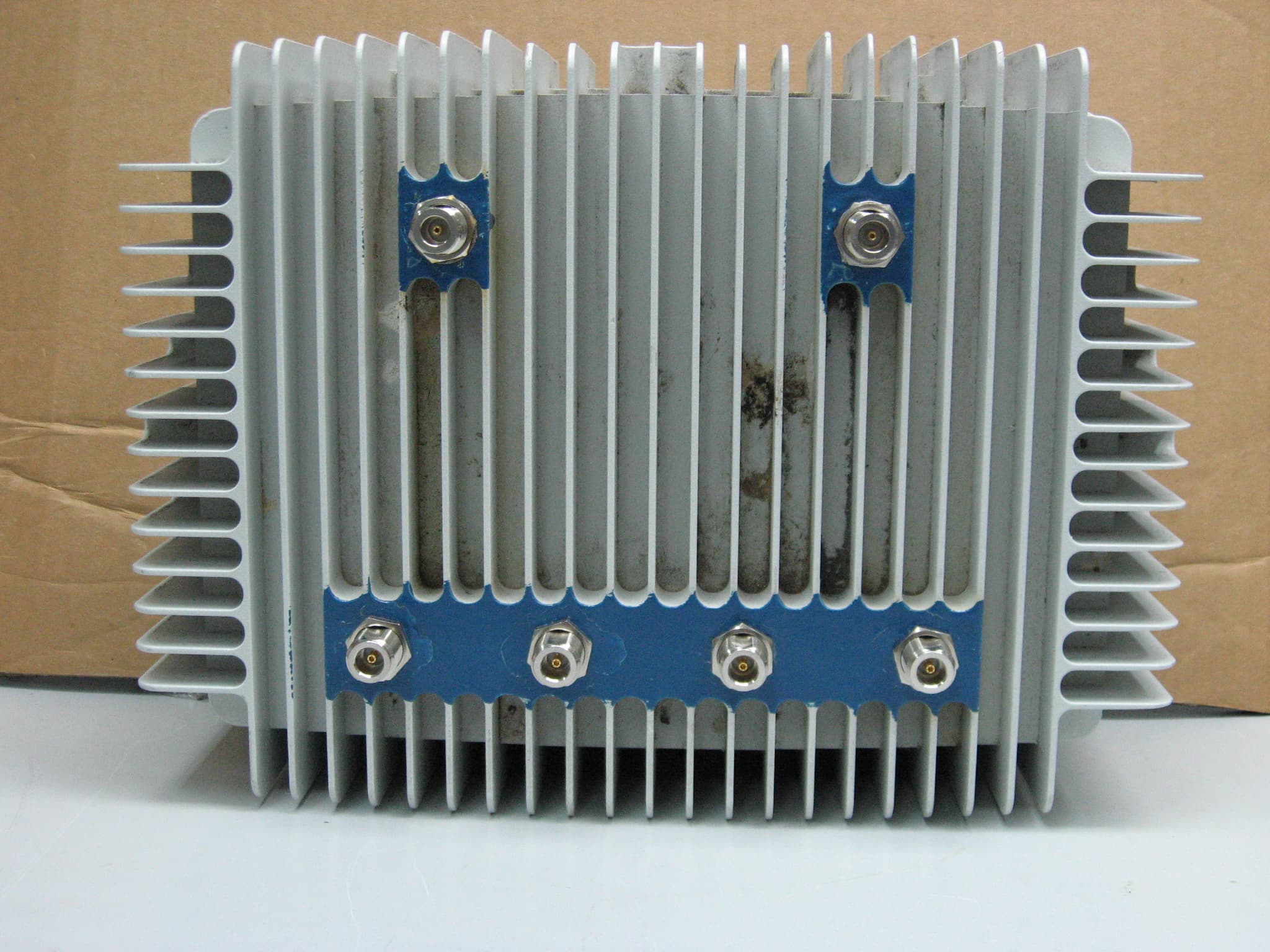
T3G-WLP-1100F-HLS
Mar 27, 2008WIRELESS LAN ACCESS POINT
Equipment Class
DTS - Digital Transmission System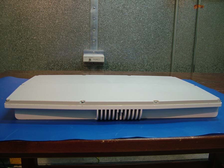
T3G-WLS-2100F-000
May 14, 2006Outdoor Phased-Array WLAN AP
Equipment Class
DSS - Part 15 Spread Spectrum Transmitter