T3G-WLS-2100F-000Outdoor Phased-Array WLAN AP
Go Networks Inc.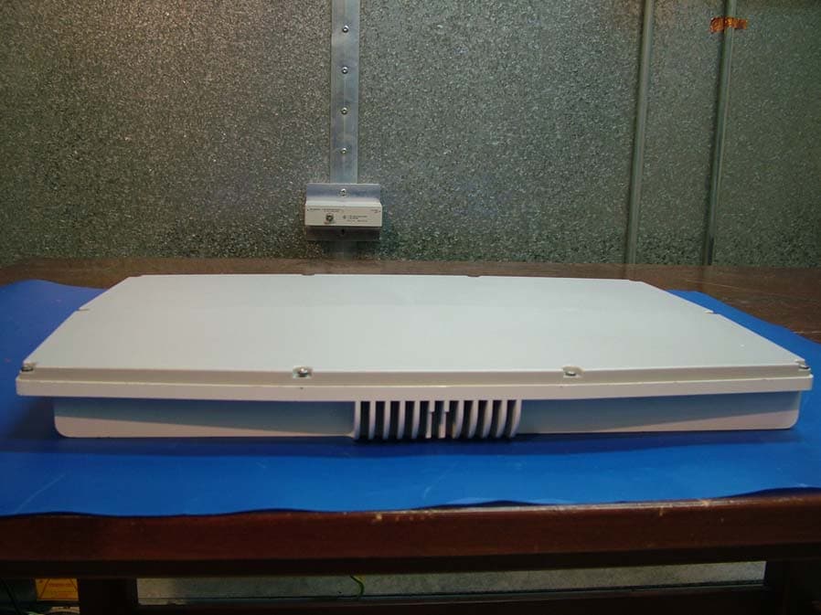
Click to zoom
Application Details
- Equipment Class
- DSS - Part 15 Spread Spectrum Transmitter
- Date of Grant
- May 14, 2006
- Application Purpose
- Original Equipment
- Date of Application
- May 03, 2006
- Equipment Note
- Outdoor Phased-Array WLAN AP
- Frequency Range
- 2412.00000000 - 2462.00000000
- Company
- Go Networks Inc.
- Country
- United States
Documents & Files
Document Text
Text extracted from the exhibit documents filed with the FCC. Open a document above to read the original.
Users Manual
GO Metro Broadband Wireless GO Metro Broadband Wireless GO Metro Broadband Wireless GO Metro Broadband Wireless Getting Started Getting Started Getting Started Getting Started Guide GuideGuide Guide GO MBW Getting Started Guide GO MBW Getting Started GuideGO MBW Getting Started Guide GO MBW Getting Started Guide Trademarks and Licensing Agreement © 2006 GO Networks, Inc. All rights reserved. All information contained in this document is protected by international copyright treaties. No information may be copied or reproduced without the express written consent of GO Networks Inc. GO Metro Broadband Wireless, Go MBW, WLAN Sector Base Station, WLS, GO Wireless Network Controller, and WNC are all trademarks of GO Networks Inc. Any duplication, transmission by any method, or storage in an information retrieval system of any part of this publication for other purposes other than those stated above is strictly prohibited without the specific written permission of GO Networks, Inc. This includes, but is not limited to, transcription into any form of computer system for audio, text, print, or visual retrieval. All rights under federal copyright laws and international laws will be strictly enforced. All other trademarks and registered trademarks are the property of their respective owners. GO Networks Inc. 1943 Landings Drive • Mountain View, CA 94043 • USA Tel +1.650.962.2000 • Fax +1.650.962.2010 Email [email protected] Version 1.03 GO MBW Getting Started Guide GO MBW Getting Started GuideGO MBW Getting Started Guide GO MBW Getting Started Guide Draft Version - Confidential - Page 1 The following information is for FCC compliance: This device complies with part 15 of the FCC Rules. Operation is subject to the following conditions: (1) this device may not cause harmful interference, and (2) this device must accept any interference received, including interference that may cause undesired operation. This equipment has been tested and found to comply with the limits of a Class B digital device, pursuant to Part 15 of the FCC Rules. These limits are designed to provide reasonable protection against harmful interference when the equipment is operated in a residential environment, this equipment generates, uses, and radiates radio frequency energy, and if not installed and used in accordance with the instructions, may cause harmful interference. However there is no guarantee that interference will not occur. To meet regulatory restrictions, the outdoor access point must be professionally installed. The Part 15 radio device operates on a non-interference basis with other devices operating at this frequency when using its internal antennas. Any changes or modifications not expressly approved by Go Networks could void the user's authority to operate the equipment. The (internal) antennas used for this transmitter must not be co-located or operating in conjunction with any other antenna or transmitter. GO MBW Getting Started Guide GO MBW Getting Started GuideGO MBW Getting Started Guide GO MBW Getting Started Guide Draft Version - Confidential - Page 2 Table of Contents Introduction...........................................................................................................................................................4 GO Wireless Network Controller (WNC)...............................................................................................................5 Deployment Options.........................................................................................................................................5 In-line Traffic Configuration..........................................................................................................................6 Non In-line Traffic Configuration ..................................................................................................................7 WNC Safety Information...................................................................................................................................9 Electrical Safety ...........................................................................................................................................9 Electro-Static Discharge Precautions (ESD)................................................................................................9 Redundant Power Supply ............................................................................................................................9 Electricity Supply........................................................................................................................................10 WNC Installation Instructions .........................................................................................................................11 Cable Connections.....................................................................................................................................11 GO WLAN Sector Base Station (WLS)...............................................................................................................13 WLS Package Components ...........................................................................................................................13 Deployment Options.......................................................................................................................................13 WLS Safety Information .................................................................................................................................14 WLS Lightning Protector............................................................................................................................14 WLS Component and Cable Connections......................................................................................................16 Ethernet Connection ...........................................................................................................................…
Text truncated - open the document above for the full version.
Cover Letter(s)
DATA SHEET GO Networks WLS Antenna Specifications The WLS2100F is an outdoor WLAN Access Point which combines multi-channel operation with state-of-the-art smart antenna technology to deliver unprecedented coverage, capacity and performance. Below are specifications for the WLS's internal Antennas: Standard Antenna – AS000004 Size: 340 x 168 mm Element Gain: 9.6dB typical (9.8dB max.) Antenna Gain: 14.8dB typical RF Connectors: MCX Hi Gain Antenna – AS000040 Size: 340 x 271 mm Element Gain: 11.6dB typical (11.8dB max.) Antenna Gain: 16.2dB typical RF Connectors: MCX DATA SHEET
Cover Letter(s)
Confidentiality Request Letter Last Update: 03/04/06 Editor: Ronen Akerman Confidentiality Request Letter 3-Apr-06 American TCB 6731 Whittier Ave Suite C110 McLean, VA 22101 USA Subject: Request of confidentiality Pursuant to Sec.0.459 of the FCC Rules, it is requested that the following information is to be held confidential on behalf of Applicants Name: • Schematics • Block Diagram • Technical description The Above information contains trade secrets and proprietary information. Public disclosure of this information will be harmful to Go Networks and will provide unjust benefits to its competitors. Yours sincerely, ______________________ Oz Leave, CEO
External Photos
External Photos Top view Bottom view Front view Side view
ID Label/Location Info
FCC label: Label Position:
Internal Photos
Internal Photos BB board top view BB board bottom view RF board top view RF board bottom view Filter board top view Filter board bottom view IF board top view IF board bottom view PS board top view PS board bottom view
RF Exposure Info
Maximum Permissible Exposure (MPE) Reference document: 47 CFR §15.247(i) & §1.1307(b)(1) Test Requirements: According to §1.1307(b)(1), systems operating under the provisions of this section shall be operated in a manner that ensures that the public is not exposed to radio frequency energy level in excess of the commission’s guideline. Limit 1mW/cm 2 Calculation Result*: Power Density = 0.78 mW/cm 2 at a sphere of 20cm. The SAR measurement is not required. Comply * Equation (3) given in OET Bulletin 65 is used to estimate the MPE distance. 2 4R P G S π = S=power density, in mW/cm 2 P=power input to the antenna, in mW G=numeric gain of the antenna, R= distance to the center of the antenna, in cm MPE levels at 20cm are calculated as follows: Frequency [MHz] Data Rate [Mbps] MPE Distance [cm] Total Output Power, 4 elements [mW] Antenna Gain [dBi] Power density [mW/cm 2 ] Limit [mW/cm 2 ] Margin [mW/cm 2 ] Single Access Channel, Worst-Case 2412 1 20 258 11.8 0.78 1 0.22 2437 1 20 240 11.8 0.72 1 0.28 2462 1 20 228 11.8 0.69 1 0.31 Dual Access Channels 2412 1 20 54.2 9.8 0.10 1 0.90 2437 1 20 62.08 9.8 0.12 1 0.88 2462 1 20 65.76 9.8 0.13 1 0.87 2412 6 20 54.96 11.8 0.17 1 0.83 2437 6 20 66.84 11.8 0.20 1 0.80 2462 6 20 59.32 11.8 0.18 1 0.82 MPE distance is calculated as follows: Frequency [MHz] Data Rate [Mbps] Power density [mW/cm 2 ] Total Output Power, 4 elements [mW] Antenna Gain [dBi] MPE Distance [cm] Limit [cm] Margin [cm] Single Access Channel, Worst-Case 2412 1 1 258 11.8 17.64 20 2.36 2437 1 1 240 11.8 17.02 20 2.98 2462 1 1 228 11.8 16.58 20 3.42 Dual Access Channels 2412 1 1 54.2 9.8 6.42 20 13.58 2437 1 1 62.1 9.8 6.87 20 13.13 2462 1 1 65.8 9.8 7.07 20 12.93 2412 6 1 55.0 11.8 8.14 20 11.86 2437 6 1 66.8 11.8 8.98 20 11.02 2462 6 1 59.3 11.8 8.45 20 11.55 When operating as single access channel, the worst case MPE occurs at 2412 MHz, 1 Mbps, 24.12 dBm power, 11.8 dBi antenna gain. The maximum exposure level in this scenario is of 0.78 mW/cm 2 at a distance of 20 cm. To maintain compliance, installations will assure a separation distance of at least 20 cm even if the calculations indicate that the MPE distance may be less. When operating as dual access channel with overlapping, the worst case MPE occurs at 2462 MHz, 1 Mbps, 17.34 dBm power, 9.8 dBi antenna gain and 2437 MHz, 6 Mbps, 18.25 dBm power, 11.8 dBi antenna gain. The maximum exposure level in this scenario is of 0.30 mW/cm 2 at a distance of 20 cm. To maintain compliance, installations will assure a separation distance of at least 20 cm even if the calculations indicate that the MPE distance may be less.
Test Report
E E E l e c t r o m m a g n e t i c C o m m p a t i b i l i t y l l e e c c t t r r o o m a a g g n n e e t t i i c c C C o o m p p a a t t i i b b i i l l i i t t y y T e s t R e p o r t T T e e s s t t R R e e p p o o r r t t T e s t R e p o r t N o : G G A P 0 2 0 4 0 6 T T e e s s t t R R e e p p o o r r t t N N o o : : G A A P P 0 0 2 2 0 0 4 4 0 0 6 6 Issued on: April 02, 2006 P r o d u c t N a m e P P r r o o d d u u c c t t N N a a m m e e W L L S - 2 1 0 F W W L S S - - 2 2 1 1 0 0 0 0 0 F F F C C I D : T T 3 G - W L S - 2 1 0 F - 0 0 F F C C C C I I D D : : T 3 3 G G - - W W L L S S - - 2 2 1 1 0 0 0 0 0 F F - - 0 0 0 0 0 0 0 T e s t e d A c c o r d i n g t o T T e e s s t t e e d d A A c c c c o o r r d d i i n n g g t t o o F C C C 4 7 C F R , P a r t 1 5 , S u b p a r t s B & C F F C C C 4 4 7 7 C C F F R R , , P P a a r r t t 1 1 5 5 , , S S u u b b p p a a r r t t s s B B & & C C T e s t s P e r f o r m e d f o r T T e e s s t t s s P P e e r r f f o o r r m m e e d d f f o o r r G o N e t w o r k s L t d . G G o o N N e e t t w w o o r r k k s s L L t t d d . . 1943 Landing Drive, Mountain View California 94043 Tel.: 1.650.962.2000 Q u a l i T e c h E M C C L a b o r a t o r y ( E C I T e l e c o m G r o u p ) Q Q u u a a l l i i T T e e c c h h E E M M C L L a a b b o o r r a a t t o o r r y y ( ( E E C C I I T T e e l l e e c c o o m m G G r r o o u u p p ) ) 30 Hasivim St, Petah-Tikva, 49517, Israel Tel: 972-3-926 8443 Fax: 972-3-928 7490 1633.01 Regis. No: 102724 Test Report: GAP 020406 Rev.3 Date: 08.05.2006 EMC Lab The information contained herein is the property of QualiTech, EMC Lab and is supplied without liability for errors or omissions. The copyright for this document vests in QualiTech, EMC Lab. All rights reserved. This Test Report may not be reproduced, by any method, without the written permission of the QualiTech, EMC Lab. If and when such permission is granted, the report must be reproduced only in the full format. T e s t p e r s o n n e l T T e e s s t t p p e e r r s s o o n n n n e e l l Tests Performed By: ----------------------------------------- Rami Nataf Report Prepared By: ----------------------------------------- Bina Talkar Report Reviewed By: ----------------------------------------- Y. Zucker QA and Lab. Manager QualiTech EMC Laboratory 1633.01 GO Networks Ltd. Page 2 of 79 WLS Test Report: GAP 020406 Rev.3 Date: 08.05.2006 EMC Lab T e s t R e p o r t d e t a i l s : T T e e s s t t R R e e p p o o r r t t d d e e t t a a i i l l s s : : Test commencement date: 05.03.2006 Test completion date: 20.03.2006 Customer’s Representative: Ronen Akerman Issued on: 02.04.2006 A s s e s s m e n t i n f o r m a t i o n : A A s s s s e e s s s s m m e e n n t t i i n n f f o o r r m m a a t t i i o o n n : : This report contained an assessment of the EUT against Electromagnetic Compatibility based upon tests carried out on the samples submitted. The results contained in this report relate only to the items tested. Manufactured products will not necessarily give identical results due to production and measurement tolerances. QualiTech, EMC Lab does not assume responsibility for any conclusion and generalization drawn from the test results with regards to other specimens or samples of type of the equipment represented by test item. The EUT was set up and exercised using the configuration, modes of operation and arrangements defined in this report only. M o d i f i c a t i o n s : M M o o d d i i f f i i c c a a t t i i o o n n s s : : Modifications made to the EUT None. Modifications made to the Test Standard None. GO Networks Ltd. Page 3 of 79 WLS Test Report: GAP 020406 Rev.3 Date: 08.05.2006 EMC Lab S u m a r y o f C o m p l i a n c e S t a a t u s S S u u m m m m m a a r r y y o o f f C C o o m m p p l l i i a a n n c c e e S S t t a t t u u s s Test Spec. Clause Test Case Remarks Notes §15.247 (a) (2) 6 dB Bandwidth Comply Measured §15.247 (b) (3) Peak Output Power Comply Measured §15.247 (c) (2)(ii)(A) Peak Output Power, antenna gain & limit Comply Calculated §15.247 (c) (2)(iii) Peak Output Power, antenna gain & limit Comply Calculated §15.247 (e) Peak power spectral density Comply Measured §15.247 (d) Conducted Spurious Emissions Comply Measured §15.247 (d) & §15.205 Radiated Emissions, Restricted Bands Comply Measured §15.109/209 Radiated Emissions Comply Measured §15.107/207 Power Line Conducted Emissions Comply Measured §15.203 Antenna Connector requirement Comply - §15.247(i) & §1.1307(b)(1) Maximum Permissible exposure (MPE) Comply Calculated 1633.01 GO Networks Ltd. Page 4 of 79 WLS Test Report: GAP 020406 Rev.3 Date: 08.05.2006 EMC Lab Table of Content T T a a b b l l e e o o f f C C o o n n t t e e n n t t 1. GENERAL DESCRIPTION...........................................................................................................................6 1.1. Description of the EUT system/test Item:.......................................................................................6 2. SETUP OF EUT...............................................................................................................................................7 Support equipment:............................................................................................................................................7 3. METHOD OF MEASUREMENTS................................................................................................................8 3.1. Conducted Measurements:..............................................................................................................8 3.2. Radiated Emission measurements:.................................................................................................. 8 3.3. Power line Emission measurements:...............................................................................................8 4. REPORT OF MEASUREMENTS AND EXAMINATIONS...............................................................…
Text truncated - open the document above for the full version.
Test Setup Photos
Test setup photos Radiated Emissions/Spurious emissions Power Line Conducted emissions Conducted Measurements
Contact Information
Applicant
Oren Avraham(Project Manager)
Technical Contact
Go NetworksRonen Ackerman
[email protected]1 650 962 2000
1943 Landings Drive · Mountian Viw, California · United States
Test Firm
QualiTech EMC Laboratory (ECI Telecom)Yossi Zucker
Technical Specifications
| # | Rule Parts | Frequency Range | Power Output |
|---|---|---|---|
| 1 | 15C | 2.41 GHz - 2.46 GHz | 258.00 mW |
Other Applications from Go Networks Inc.
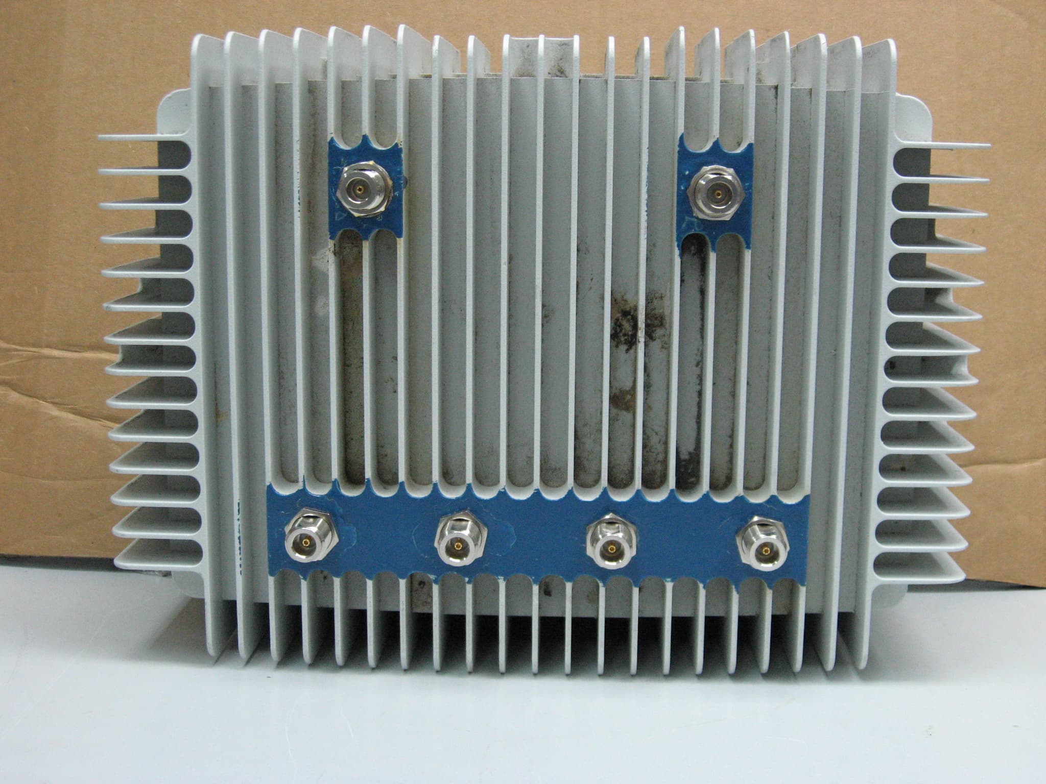
T3G-WLP-1100F-HLS
Mar 27, 2008WIRELESS LAN ACCESS POINT
Equipment Class
DTS - Digital Transmission System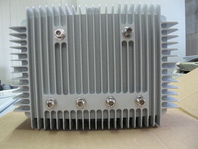
T3G-WLP-1100F-000
Sep 24, 2006Outdoor Wireless LAN Access Point
Equipment Class
DTS - Digital Transmission System