T3YZ90LED camera light with wireless connectivity
Zylight LLC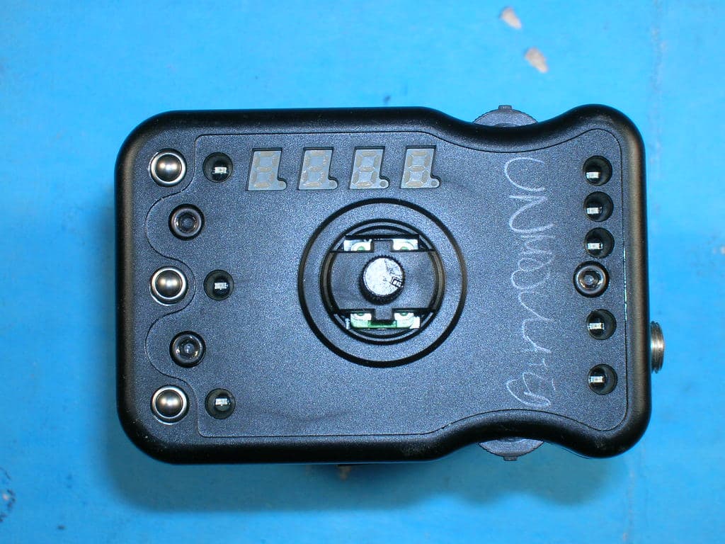
Click to zoom
Application Details
- Equipment Class
- DTS - Digital Transmission System
- Date of Grant
- Jan 28, 2010
- Application Purpose
- Original Equipment
- Date of Application
- Jan 27, 2010
- Equipment Note
- LED camera light with wireless connectivity
- Frequency Range
- 2404.00000000 - 2450.00000000
- Company
- Zylight LLC
- Country
- United States
Documents & Files
Document Text
Text extracted from the exhibit documents filed with the FCC. Open a document above to read the original.
Users Manual
MECHANICAL SIZE: WEIGHT: MOUNTING: ELECTRICAL INPUT: DC PLUG: AC ADAPTER: POWER: WIRELESS FREQ: CHANNELS: OUTPUT BEAM ANGLE: DIMMING: PRESETS: LED LIFE: 5.3" x 3.0" x 2.0" [135mm x 76mm x 51mm] 16oz. [454g] Two: 1/4"-20 Socket 7-24V DC Positive Locking Type OD: 5.5mm, ID: 2.1mm 100-240V, 50-60Hz 30W max. [2.5A max. @ 12V] 2.45GHz 10 60° 2 Ө ½-intensity, 130° total 1% - 100% White Mode - Two: Daylight, Tungsten Gel Mode - 2500°K ↔ 9000°K in 50°K steps, ± GREEN Color Mode - Two: User defined 50,000 Hrs. min. before factory re-calibration Z90 SPECIFICATIONS THE ZYLIGHT Z90 IS PROTECTED BY THE FOLLOWING U.S. AND FOREIGN PATENTS WITH OTHER U.S. AND FOREIGN PATENTS PENDING: US 6,340,868 US 6,806,659 CA 2,302,227 EP 1 016 062 B1 AU 757000 B2 HK 1025416 DE 698 07 092 C0 Zylight LLC PO Box 54 Chelmsford, MA 01824 +1-978-244-0011 www.zylight.com This device complies with part 15 of the FCC Rules. Operation is subject to the following two conditions: (1) This device may not cause harmful interference, and (2) this device must accept any interference received, including interference that may cause undesired operation. Changes or modifications not expressly approved by the party responsible for compli-ance could void the user's authority to operate the equipment. This equipment has been tested and found to comply with the limits for a Class B digital device, pursuant to Part 15 of the FCC Rules. These limits are designed to provide reasonable protection against harmful interference in a residential installation. This equipment generates, uses and can radiate radio frequency energy and, if not installed and used in accordance with the instructions, may cause harmful interference to radio communications. However, there is no guarantee that interference will not occur in a particular installation. If this equipment does cause harmful interference to radio or television reception, which can be determined by turning the equipment off and on, the user is encouraged to try to correct the interference by one or more of the following measures: (1) Reorient or relocate the receiving antenna; (2) Increase the separation between the equipment and receiver; (3) Connect the equipment into an outlet on a circuit different from that to which the receiver is connected; (4) Consult the dealer or an experienced radio/TV technician for help. US 6,608,453 US 6,777,891 US 6,016,038 US 6,150,774 US 6,211,626 US 6,788,011 © Copyright 2003-2010 Zylight LLC. All rights reserved. 24-07002 Rev. 2 Z90 Intelligent LED Light USER GUIDE 2 Thank you for choosing Zylight. We at Zylight are happy that you chose the Z90. There are many lighting systems out there to choose from, and we think you will agree that what you hold in your hands is the most versatile production light instrument on the planet. At Zylight our mission is to bring truly intelligent lighting to your shoots. With its small size and weight, the amazing HD-led™ module, and ZyLink™ technology, the Z90 represents the most advanced lighting instru- ment for film and video production today. The people who engineered and built your Z90 are the same folks who will answer any questions you may have about it. We use our lights everyday, and would love to hear any comments or suggestions you may have about how we can improve our products. The Z90 may be small, but what it will do for your shoots is big news! Enjoy, - The Zylight Team [email protected] www.zylight.com 7 Using the Accessory Adapter Overview The Z90’s Accessory Adapter allows you to mount most standard lighting accessories with a 3-inch [76mm] m ounting flange, such as a soft box or barndoors. Accessories with a mounting flange up to 0.075” [1.9mm] thick can be mounted. Mounting the Accessory Adapter The Accessory adapter slides onto the Z90 from either side of the light. 1. Position the Accessory Adapte r parallel with the front of the Z90 with the locking tab resting on the front window. Position the two spring clips so that they are touching the rounded corners on the short side of the heatsink. 2. Slide the Adapter onto the light, expanding the two spring clips as the heatsink rails slide between the heatsink fins. Mounting the Accessory To mount the accessory, slide its flange over the locking tab and under the two accessory flanges. Removing the Accessory To remove the accessory, gently depress the locking tab and slide the accessory out of the flanges. Removing the Accessory Adapter To remove the Accessory Adapter, sli de the Adapter off of the light in the opposite direction as it was installed. SPRING CLIPS LOCKING TAB HEATSINK RAILS ACCESSORY FLANGES 6 Using ZyLink ™ (patent pending) Overview Every Z90 can be wirelessly linked to other Zylights (Z50 or Z90), creating a group of lights that operate in concert as if they were one larger light. The group can contain as many Zylights as you ne ed. Adjusting the controls on one Zylight in the group will change all of the other lights in the group. You can have Zylights operating indepen dently at the same time you have linked Zylights. Any independent Zylight can be added to an existing group, and any linked Zylight can be removed from a group. ZyLink ™ settings are saved even if power is removed from the Z90. This allows you to remove power from your lights during down-time, and resume lighting later without having to re-group the lights. ZyLink ™ QuickStart 1. Plug in at least two Z90s. 2. On one Z90, push in and hold the bottom thumbwheel until the ZYLINK indicator glows. 3. Select the desired ZyLink ™ channel by pushing and releasing bottom thumbwheel until the correct channel is displayed. 4. Repeat steps 2 & 3 with other Z90s you wish to link together. 5. That’s it! When the controls are adjusted on one of the Z90s on the same channel, all of the lights on that channel will change. Enabling & Disabling ZyLink ™ To turn ZyLink ™ on or off, push in and hold the bottom thumbwheel for ~1 second. The ZYLINK indicator will glow whenever ZyLink ™ is enabled. C…
Text truncated - open the document above for the full version.
Cover Letter(s)
7/22/09 To Whom It May Concern: This is your letter of authorization to accept our appointment of CKC Certification Services, LLC as Agent for Zylight, LLC of 152 SE 5 th Ave, Hillsboro, OR 97123 to sign applications before the agency on our behalf, and to receive and exchange data between our company and the agency in connection with certification. Sincerely, Nicholas Foster Principal Engineer
Cover Letter(s)
1/26/10 To Whom It May Concern: This is your letter of authorization to accept our appointment of Nicholas Foster to sign letters and applications for any filings with the agency on our behalf, and to receive and exchange data between our company, the agents company and the agency in connection with certification for any products that our company owns or manufactures. Sincerely, James Collias Zylight LLC 152 SE 5 th Avenue Hillsboro, OR 97123 978-244-0011
Cover Letter(s)
7/30/09 Federal Communications Commission 7435 Oakland Mills Road Columbia, MD 21046 Gentlemen: This letter is to comply with Section 0.457(d)(2)(i) and Section 0.459 pertaining to confidential material. Zylight, LLC would like the following documents regarding this submission for FCC ID: T3YZ90 to be kept confidential. 1.Schematic 2.Block Diagram 3.Operational Description The above material contains trade secrets or technical data, which would customarily be guarded from competitors. We do not want these documents to be accessible to the general public. Sincerely, Nicholas Foster Principal Engineer Zylight, LLC
Cover Letter(s)
Non-Conformities FCC ID : T3YZ90 (CKC CS Ref # E10-000004-FCC-01) The items listed below represent requests for information following review of this application for certification under United S tates (FCC) regulations. Further question may arise pending review of responses to these items. OK ID # Non-Conformity or Comment Subm itted Response Respondent / Date of Response √ C 1 Please remove the FCC logo for D eclaration of Conformity from your FCC ID label for you are Certifying the transmitter and Verifying the Digital/Receiver portion. Also, this label appears to be a “stick-on” type of label. Please describe how this label is to be applied since “stick-on” labels are not approved. Ref: 15.19(b)(4) OK – C Kendall 1/27/10 T he "sticker" is a plastic label, silkscreen printed and coated with a laminate to make it permanent. It is applied to the device using a 3M permanent plastic adhesive. The same label with the same adhesive was approved for use with the Z50 device in 2005. The revised "FCC ‐ free" The label is provided. N ick Foster 1/27/10 √ C 2 Please submit two Letters of Confidentiality: 1) for Permanent Confidentiality for the Schematics, Block Diagram, & Operational Description and 2) for Temporary Confidentiality (180 days after release) for the interior photos. Note: special permission by the FCC has to be obtained for making the Interior Photos permanently Confidential. Typical reason for holding Interior Photos Confidential is: it is a security device used by law enforcement and the interior will be potted. OK – C Kendall 1/27/10 T he attached revised confidentiality letter no longer requests confidentiality for internal photographs. However, I have requested confidentiality for the Operational Description and Block Diagram. Hopefully that's OK. N ick Foster 1/27/10 √ C 3 Please provide an Operational Description for your product describing briefly how the circuits function, how they operate, how it is modulated to include a description of the ground system and antenna. Ref: FCC 2.1033(b)(4). OK – C Kendall 1/27/10 O perational Description Provided. N ick Foster 1/27/10 √ C 4 Please provide a Block Diagram for your product showing the frequency of all oscillators in the device. The tuning range(s) and B lock Diagram Provided. N ick Foster intermediate frequencies shall be i ndicated at each block. Remember the Schematic is not a substitute for the Block Diagram. Ref: FCC Part 2.1033(b)(5). OK – C Kendall 1/27/10 1 /27/10 √ C 5 Schematic should include all portions of the RF sections of the transmitter. Where is the oscillator circuitry shown on the schematic? Ref: 2.1033(b)(5). OK – C Kendall 1/27/10 T he oscillator for the transceiver is internal to the CC2430 chip and is derived from the 32MHz oscillator labeled X1 in the schematic. N ick Foster 1/27/10 √ C 6 One needs to change the signer of the cover letters to James Collias who is the contact for Zylight, LLC, change the contact information for the Grantee, or get James Collias to provide a letter authorizing Nicolas Foster to act on his behalf. OK – C Kendall 1/27/10 A uthorization Letter providing permission for Nick Foster to sign letters on James Collias’s behalf provided. N ick Foster 1/27/10 √ C 7 Please add to your User's Manual a statement regarding the RF exposure. OK – C Kendall 1/27/10 Please disregard the request for users manual statement for RF exposure. Since the power output is below the requirement for RF exposure evaluation, this statement is unnecessary. We'll close the issue on our end. Per discussion with Randy Clark of CKC, language regarding RF exposure will not be added to the manual. Randal Clark 1/21/10 Nick Foster 1/27/10 √ C 8 Please provide a diagram or photo showing FCC ID label placement. Label provided does not show location of FCC ID label placement. C Kendall - 1/27/10 It’s OK now – C Kendall 1/27/10 P rovided photograph showing FCC ID label placement on the device. Un ‐ cropped Photo Provided. The previous one I sent w as not the correct photo. N ick Foster 1/27/10 Nick Foster 1/27/10 √ C 9 In accordance with 15.105(b) Information to the User: A Class B device should have the following stat ement incorporated in the User’s Manual. For a Class B digital devi ce or peripheral, the instructions P rovided revised User's Manual including Class B statement. N ick Fo s ter 1/27/10 furnished the user shall include the following or similar statement, placed in a prominent location in the text of the manual: This equipment has been tested and found to comply with the limits for a Class B digital device, pursuant to Part 15 of the FCC Rules. These limits are designed to provid e reasonable protection against harmful interference in a residential installation. This equipment generates, uses and can radiate ra dio frequency energy and, if not installed and used in accordance with the instructions, may cause harmful interference to radio communications. However, there is no guarantee that interference will not occur in a particular installation. If this equipment does cause ha rmful interference to radio or television reception, which can be determined by turning the equipment off and on, the user is encouraged to try to correct the interference by one or more of the following measures: -- Reorient or relocate the receiving antenna. -- Increase the separation betw een the equipment and receiver. -- Connect the equipment into an outlet on a circuit different from that to which the receiver is connected. -- Consult the dealer or an experi enced radio/TV tech nician for help. According to the test report, this is a Class B device;therefore it should have this statement placed into the User’s Manual and not the Class A statement that is in there no w. Please make this change to the User’s Manual. OK – C Kendall 1/27/10 √ C/TL 10 Although 15.247 devices are excluded from RF Exposure Evaluation, it is a requirement to provide a statement indicating the exemption. OK – C Kendall 1/27/10 P er discussion wit…
Text truncated - open the document above for the full version.
Test Report
Page 1 of 60 Report No: FC09-006A TESTING CERT #803.01, 803.02, 803.05, 803.06 ZYLIGHT LLC ADDENDUM TEST REPORT TO FC09-006 FOR THE LED CAMERA LIGHT WITH WIRELESS CONNECTIVITY, Z90 FCC PART 15 SUBPART C SECTIONS 15.207 & 15.247, SUBPART B SECTIONS 15.107 & 15.109 CLASS B AND RSS-210 ISSUE 7 TESTING DATE OF ISSUE: JANUARY 20, 2010 PREPARED FOR: Zylight LLC 4372 17th Street San Francisco, CA 94114 PREPARED BY: Joyce Walker CKC Laboratories, Inc. 5046 Sierra Pines Drive Mariposa, CA 95338 W.O. No.: 88886 Date of test: December 8-17, 2008 Report No.: FC09-006A This report contains a total of 60 pages and may be reproduced in full only. Partial reproduction may only be done with the written consent of CKC Laboratories, Inc. The results in this report apply only to the items tested, as identified herein. Page 2 of 60 Report No: FC09-006A TABLE OF CONTENTS Administrative Information .............................................................................................3 Approvals .........................................................................................................................3 Summary of Results .........................................................................................................4 Conditions During Testing ...............................................................................................4 FCC 15.31(m) Number Of Channels ...............................................................................5 FCC 15.33(a) Frequency Ranges Tested .........................................................................5 FCC 15.203 Antenna Requirements ................................................................................5 EUT Operating Frequency ...............................................................................................5 Power Output ...................................................................................................................5 Equipment Under Test (EUT) Description ......................................................................6 Equipment Under Test .....................................................................................................6 Peripheral Devices ...........................................................................................................6 Report of Emissions Measurements.................................................................................7 Testing Parameters ...............................................................................................7 FCC 15.31(e) – Voltage Variations .................................................................................9 FCC 15.107 – AC Conducted Emissions .........................................................................12 FCC 15.109 – Radiated Emissions ..................................................................................21 FCC 15.207 – AC Conducted Emissions .........................................................................26 FCC 15.247(a)(2) – 6dB Bandwidth ................................................................................35 FCC 15.247(b)(3) – RF Power Output ............................................................................39 FCC 15.247(d) – Band Edge ............................................................................................41 FCC 15.247(d) – OATS Radiated Spurious Emissions ...................................................44 FCC 15.247(e) – Peak Power Spectral Density ...............................................................52 RSS-210 – 99% Bandwidth .............................................................................................56 Page 3 of 60 Report No: FC09-006A ADMINISTRATIVE INFORMATION DATE OF TEST: December 8-17, 2008 DATE OF RECEIPT: December 8, 2008 REPRESENTATIVE: Nick Foster MANUFACTURER: Zylight LLC 4372 17th Street San Francisco, CA 94114 TEST LOCATION: CKC Laboratories, Inc. 1120 Fulton Place Fremont, CA 94539 TEST METHOD: ANSI C63.4 (2003), RSS-210 Issue 7 and RSS GEN Issue 2 PURPOSE OF TEST: Original: To perform the testing of the LED Camera Light with wireless connectivity, Z90 with the requirements for FCC Part 15 Subpart C Sections 15.207 & 15.247, Subpart B Sections 15.107 & 15.109 Class B and RSS-210 devices. Addendum A: To correct an error in the testing dates from 2009 to 2008, to correct the Powe r Output from .000217 to .000117 on page 41 and to include this corrected Power Output information on page 5. APPROVALS Steve Behm, Director of Engineering Services QUALITY ASSURANCE: TEST PERSONNEL: Amrinder Brar, EMC Engineer/Lab Manager Art Rice, Senior EMC Engineer Page 4 of 60 Report No: FC09-006A SUMMARY OF RESULTS Test Specification Results Voltage Variations FCC 15.31(e) Pass Conducted Emissions FCC Part 15 Subpart B Section 15.107 Class B Pass Radiated Emissions FCC Part 15 Subpart B Section 15.109 Class B Pass Conducted Emissions FCC Part 15 Subpart B Section 15.207 Class B Pass 6dB Bandwidth FCC 15.247(a)(2) Pass RF Power Output FCC 15.247(b)(3) Pass Band Edge FCC 15.247(d) Pass OATS Radiated Spurious Emissions FCC 15.247(d) Pass Peak Power Spectral Density FCC 15.247(e) Pass 99% Bandwidth RSS-210 Issue 7 & RSS GEN Issue 2 Pass Site File No. FCC 958979 IC 3082B-1 CONDITIONS DURING TESTING One pass through ferrite on DC cord at power supply (Etronic F5-NF-50W-02). Page 5 of 60 Report No: FC09-006A FCC 15.31(m) Number Of Channels This device was tested on three channels. FCC 15.33(a) Frequency Ranges Tested 15.107 Conducted Emissions: 150 kHz – 30 MHz 15.109 Radiated Emissions: 9 kHz – 1000 MHz 15.207 Conducted Emissions: 150 kHz – 30 MHz 15.209/15.247 Radiated Emissions: 9 kHz – 25 GHz FCC 15.203 Antenna Requirements The antenna is an integral part of the EUT and is non-removable; therefore the EUT complies with Section 15.203 of the FCC rules. EUT Operating Frequency The EUT was operating in the 2400-2483.5 MHz range. Power Output 0.000117 Watts Page 6 of 60 Report No:…
Text truncated - open the document above for the full version.
Contact Information
Applicant
James Collias(Engineering Director)
Technical Contact
CKC Certification Services, LLCJessina Hunter
[email protected]209-966-5240
5046 Sierra Pines Dr. · Mariposa, California · United States
Test Firm
CKC Laboratories, Inc.Steve Behm
Technical Specifications
| # | Rule Parts | Frequency Range | Power Output |
|---|---|---|---|
| 1 | 15C | 2.40 GHz - 2.45 GHz | 117.00 µW |
Other Applications from Zylight LLC
T3YNZ
Dec 22, 2015LED Light
Equipment Class
DTS - Digital Transmission System
T3YZ50
Aug 27, 2006Z50
Equipment Class
DTS - Digital Transmission System