T6BFAB4001BIOMECHANICAL MOVEMENT RECORDER
NEMOTO KYORINDO Co., Ltd.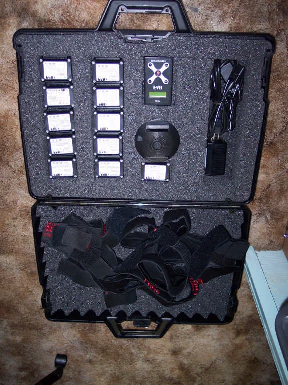
Click to zoom
Application Details
- Equipment Class
- DXT - Part 15 Low Power Transceiver, Rx Verified
- Date of Grant
- Apr 26, 2007
- Application Purpose
- Original Equipment
- Date of Application
- Apr 25, 2007
- Equipment Note
- BIOMECHANICAL MOVEMENT RECORDER
- Frequency Range
- 916.50000000 - 916.50000000
- Company
- NEMOTO KYORINDO Co., Ltd.
- Country
- Japan
Documents & Files
Document Text
Text extracted from the exhibit documents filed with the FCC. Open a document above to read the original.
Users Manual
Copyright Biosyn Systems Inc. April 2005 Hardware User Manual Prepared By Michael Lee, William Hue, Russell McNeil Updated: April 20, 2007 ii Contents 1. Introduction................................................................................................................................1 1.1. List of Physical Components.......................................................................................2 2. FAB Hardware Set-Up...............................................................................................................7 2.1. Belt Clip Set-Up..........................................................................................................7 2.2. Date and Time Setup...................................................................................................7 2.3. Sensor Set-Up..............................................................................................................8 2.3.1. 3D Sensors....................................................................................................8 2.3.2. Foot Sensors.................................................................................................8 3. Belt Clip Modes..........................................................................................................................9 3.1. Data Recording Mode..................................................................................................9 3.1.1. View Battery Voltage...................................................................................9 3.1.2. Recording Data.............................................................................................9 3.1.2.1. Data Collection Error Handling..........................................13 3.1.2.1.1. Momentary Radio Drop-out Error.................13 3.1.2.1.2. Sensor Failure Error........................................13 3.1.2.1.3. Slow Memory Card Error...............................14 3.1.2.1.4. Low Battery Voltage Warning........................14 3.1.2.2. Attaching Sensors to the Body.............................................15 3.1.2.2.1. Sensor Orientation...........................................15 3.1.2.2.2. Sensor Locations...............................................15 3.1.3. Setting the Date and Time..........................................................................16 3.2. Clinician Mode..........................................................................................................16 3.2.1. Setting up the Sensor List...........................................................................16 3.2.2. Recording Data...........................................................................................17 1. Introduction The FAB System aids in assessment of human biomechanical movement. It consists of a number of electronic sensors and a data-collection (“Belt Clip”) unit to be worn or located near the subject being evaluated. This document describes how to set-up and use the FAB data collection device with sensors. Model: FAB4001 IC (Industry Canada): 6461A-FAB4001 FCC ID: T6DFAB4001 “This device has been tested and complies with the regulations of Industry Canada Technical Standard RSS-210.” NOTE: “This equipment has been tested and found to comply with the limits for a Class A digital device, pursuant to Part 15 of the FCC rules. These limits are designed to provide reasonable protection against harmful interference when the equipment is operated in a commercial environment. This equipment generates, uses, and can radiate radio frequency energy and, if not installed and used in accordance with the instruction manual, may cause harmful interference to radio communications. Operation of this equipment in a residential area is likely to cause harmful interference in which case the user will be required to correct the interference at their own expense. Operation is subject to the following two conditions: (1) this device may not cause harmful interference and (2) this device must accept and harmful interference received, including interference that may cause undesired operation.” Caution! Changes or modifications to this equipment, not expressly approved by the manufacturer could void the user’s authority to operate the equipment. NOTE: THE MANUFACTURER IS NOT RESPONSIBLE FOR ANY RADIO OR TV INTERFERENCE CAUSED BY UNAUTHORIZED MODIFICATIONS TO THIS EQUIPMENT. SUCH MODIFICATIONS COULD VOID THE USER'S AUTHORITY TO OPERATE THE EQUIPMENT. 2 1.1. List of Physical Components The FAB Phase 1 System consists of the following items: 1. Left Arm Sensor (ID 1) 2. Right Arm Sensor (ID 2) 3. Upper Back Sensor (ID 3) 4. Lower Back Sensor (ID 4) 5. Left Leg Sensor (ID 5) 6. Right Leg Sensor (ID 6) 7. Left Wrist (ID 7) 8. Right Wrist (ID 8) 9. Left Calf (ID 9) 10. Right Calf (ID 10) 11. Left Foot (ID 128) 12. Right Foot (ID 129) 13. Left and Right Foot Transducers (black insoles) 14. Belt Clip with Batteries 15. Memory Card 16. Memory Card Reader with Software CD and USB Cable 17. FAB Software CD 18. This Manual Limited Warranty and Technical Support United States and Canada This document includes warranty information for Biosyn Systems’ FAB Hardware products in Canada and the United States. Product Warranty Periods Product Duration of Warranty period Sensor hardware 3 years Foot transducers 1 year - excluding natural wear and tear Included hardware battery charger and batteries 1 year Included straps Not warranted Biosyn Systems Inc. (for U.S. and Canadian Sales) (Biosyn) warrants this product against defects in material or workmanship for the time periods and as set forth above. Pursuant to this Limited Warranty, Biosyn will, at its option, (i) repair the product using new or refurbished parts or (ii) replace the product with a new or refurbished product. For purposes of this Limited Warranty, “refurbished” means a product or part that has been returned to its original specifications. In the event of a defect, these are your exclusive re…
Text truncated - open the document above for the full version.
Cover Letter(s)
15649 107a Ave Surrey, B.C., Canada V4N3H9 Federal Communications Commission Authorization and Evaluation Division Confidentiality Request regarding application for certification of FCC ID: FAB4001. Pursuant to Sections 0.457 and 0.459 of the Commission’s Rules, we hereby request confidential treatment of information accompanying this application as outlined below: Exhibit Type File Name Theory of Operation FAB4001_OpDes.pdf Bill of Material FAB4001_BOM.pdf Radio Time Slots Diagram FAB4001_RadTimSlt.pdf Schematic Diagram FAB4001_Schem System Block Diagram FAB4001_BlkDia The above materials contain trade secrets and proprietary information not customarily released to the public. The public disclosure of these materials may be harmful to the applicant and provide unjustified benefits to its competitors. The applicant understands that pursuant to Section 0.457 of the Rules, disclosure of this application and all accompanying documentation will not be made before the date of the Grant for this application. Sincerely, Russell McNeil President Biosyn Systems Inc.
Cover Letter(s)
15649 107a Ave Surrey, B.C., V4N3H9 604-230-2503 April 30, 2007 To Whom It May Concern, Regarding: FCC submission for FCC ID: T6BFAB4001. This is a request by Biosyn Systems for the Dismissal of the Application for the submission of FCC ID: T6BFAB4001. This request is being made since the application was made using the incorrect Grantee Code T6B. The Grantee Code that should have been used is T6D. We will be reapplying for the Grant as FCC ID T6DFAB4001. Sincerely, Russell McNeil, President Biosyn Systems Inc.
External Photos
Biosyn FAB Sensor system Arm/Leg/Foot Sensor Back Sensor Belt Clip Display
Test Report
EMC Compatibility Testing Report Rev. 2.0 BIOSYN Systems - FAB Report Number: 03148 Page 2 of 37 Index Section I: Information for Test Report of Measurements .................................................................... 3 Section II: Report of Measurements to IC RSS-210 Iss.6 & FCC CFR47 Part 15/B............................ 5 Section III: Report of Measurements to IC RSS-210 Iss. 6 Annex 2.9 - Emissions Testing ................. 6 Part 1 - Conducted Emission Testing in Idle/Receive Mode ............................................... 7 Part 2 - Radiated Emission Testing in Idle/ Receive Mode ................................................. 8 Part 3 - Radiated Emissions – Transmit Mode.................................................................... 9 Part 4 - Output Power and EIRP Emissions ...................................................................... 10 Section IV: Report of Measurements to FCC CFR47 Part 15/B & 15/C .............................................. 11 Part 1 - Conducted Emissions - AC Mains/ Idle Mode ...................................................... 13 Part 2 - Radiated Emission - Unintentional Testing........................................................... 14 Part 3 - Antenna Requirement - 15.203............................................................................. 15 Part 4 - Radiated Emission - Intentional /Operation within the required bands - 15.249.. 16 Section V: Report of Measurement for 60601-1-2 Summary ............................................................. 18 Part 1 - Limits for Harmonic Current Emissions ................................................................ 19 Part 2 - Limitation of Voltage Fluctuations and Flicker ...................................................... 21 Part 3 - Electrostatic Discharge ......................................................................................... 22 Part 4 - Radiated Immunity Testing (A.M.) ........................................................................ 24 Part 5 - EFT/Burst Testing (Fast Transient - AC Power Supply) ....................................... 25 Part 6 - Surge Transient Immunity .................................................................................... 27 Part 7 - Voltage Dips and Interruptions Testing................................................................. 28 Appendix A: EUT Photos ....................................................................................................................... 29 Appendix B: Intentional Emission Data and Plots.................................................................................. 32 Appendix C: Unintentional Emission Data and Plots ............................................................................. 35 EMC Compatibility Testing Report Rev. 2.0 BIOSYN Systems - FAB Report Number: 03148 Page 3 of 37 Section I: Information for Test Report of Measurements Testing Details TESTED BY: Emission Testing: David Johanson Immunity Testing: Parminder Singh TEST CONDITIONS: Temperature and Humidity: TEST VOLTAGE: 120Vac 60Hz/240Vac 50Hz and Battery Pack Test Facilities Protocol Data Systems Inc., EMC Lab 28945 McTavish Rd. Abbotsford BC, Canada, V4X 2E7 FCC O.A.T.S. Registration Number 96437 Industry Canada O.A.T.S. Registration Number IC3384 Test Equipment List EMISSIONS: Manufacturer Model Equipment Description Serial No. Last Cal Next Cal HP 85650A CDN Quasi-Peak Adapter 2043A00240 22/03/05 22/03/06 HP 85662A Spectrum Analyzer Display 2318A05184 22/03/05 22/03/06 HP 8566B Spectrum Analyzer RF Section 2241A02102 22/03/05 22/03/06 HP 85685A RF-Preselector 3107A01222 22/03/05 22/03/06 A.H. Systems SAS-200/510 Antenna Log Periodic 761 04/03/05 04/03/06 EMCO 3105 Antenna DRG Horn (Med) 2024 25/02/05 25/02/06 LaPlace Instruments AC1000 Low Distortion Power Source 138041 12/12/05 12/12/06 Thurlby Thandar HA1600 Power and Harmonics Analyzer 140108 13/12/05 13/12/06 EMCO 3825 2 LISN (25A 50ohm 50/250uH 10k-100M) 9509-2470 20/07/05 20/07/06 EMCO 3110B Antenna Biconical (Type 3) 9401-1850 01/03/05 01/03/06 Rhientech Custom Antenna Mast N/A N/A N/A Protocol EMC Custom Turntable N/A N/A N/A IMMUNITY: Manufacturer Model Equipment Description Serial No. Last Cal Next Cal EIN 3100L RF Amplifier 309 N/A N/A Amplifier Research 30W1000M7 RF Amplifier 22606 N/A N/A Amplifier Research FP4000 Field Probe 21776 14/05/05 14/05/06 Amplifier Research TC2000 Test Cell 22666 14/05/05 14/05/06 HP 8657A Signal Generator 2913A00373 09/05/05 09/05/06 Schaffner NSG432 ESD Simulator: 1243 16/12/05 16/12/06 Keytek CM-BASE CE Combination Tester * 9611222 08/10/05 08/10/06 Schaffner CDN 125 Coupling Network 310 09/05/05 09/05/06 EMCO 95236-1 Bulk Injection Clamp 50958 27/02/05 27/02/06 The CE-Master CM-BASE will perform the Electrical Fast Transient test, the Surge Transient Test, the Power Frequency Magnetic Field Test, the pulsed Magnetic Field test and the Voltage Dips and Interruptions test all according Measurement Uncertainty Parameter Uncertainty Radio Frequency ±1 x 10⁻⁵ Total RF power, conducted ±1,5 dB RF power density, conducted ±3 dB Spurious emissions, conducted ±3 dB All emissions, radiated ±6 dB Temperature ±1 ° C Humidity ±5 % DC and low frequency voltages ±3 % EMC Compatibility Testing Report Rev. 2.0 BIOSYN Systems - FAB Report Number: 03148 Page 4 of 37 Company Tested: NAME: BIOSYN Systems ADDRESS: 15649 107A Avenue Surrey, BC V4N 3H9 CONTACT: Mr. Russell McNeil EMAIL: [email protected] NUMBER: 604-375-2697 Equipment Under Test THE TEST SYSTEM: EUT: FAB System Manufacturer: Biosyn Systems Part Number: Serial Number: TEST VOLTAGE: Internal Battery Pack (DC rechargeable internal pack) CABLING: Cable Pins Connector Load/Termination Shielded Ferrites Power 2 Mini-DC No No No TEST SET-UP: The FAB System is comprised of 10 x 3 Dimension Sensors, 2 Foot Pressure Sensors and 1 x Belt clip module. The 3 Dimension sensors are placed on various parts of the body and are used to record the 3 Dimensio…
Text truncated - open the document above for the full version.
Test Setup Photos
EUT Setup Photos Emissions Test Setup of FAB Front View Emissions Test Setup of Main Unit Up Close Emission Setup of Back Unit Emissions Test Setup of Foot Pads Emission Set up of FAB Sensors
Contact Information
Applicant
Masahiro Sakakibara
Test Firm
Protocol LabsRobert Stirling
Technical Specifications
| # | Rule Parts | Frequency Range | Power Output |
|---|---|---|---|
| 1 | 15C | 916.5 MHz - 916.5 MHz | - |
Other Applications from NEMOTO KYORINDO Co., Ltd.
T6B0001
Apr 20, 2006Dual Shot Alpha
Equipment Class
DXX - Part 15 Low Power Communication Device Transmitter