Text extracted from the exhibit documents filed with the FCC. Open a document above to read the original.
Publication No. OME-R06601-D Date: Jul/2006 PRINTED IN JAPAN FURUNO SYSTEMS CO., LTD. USER’S MANUAL MODEL: finpad 500f A TABLE OF CONTENTS FOREWORDS.............................................................................................................. C DISCLAIMER............................................................................................................... C PRECAUTIONS ON USING WIRELESS LAN............................................................. D SAFETY LEVELS & MARKS.......................................................................................G HANDLING PRECAUTIONS FOR THIS UNIT............................................................. H TRADEMARKS............................................................................................................ K COPYRIGHT................................................................................................................ K 1. Features..................................................................................................................1 2. System Configuration............................................................................................3 3. Controls & Switches..............................................................................................4 4. Li-ion Battery Pack Handling Precautions...........................................................8 5. Charging Li-ion Battery Pack..............................................................................11 6. Charging Backup Battery....................................................................................13 7. Replacing Li-ion Battery Pack............................................................................14 8. Power-ON/OFF.....................................................................................................16 9. Setup Utility..........................................................................................................17 10. Adjusting Screen Contrast..................................................................................21 11. LCD Backlight ON/OFF........................................................................................22 12. Using Laser Scanner...........................................................................................23 13. Bluetooth Communication..................................................................................25 14. Attaching Handstrap............................................................................................26 15. Daily Maintenance................................................................................................27 16. Before calling service..........................................................................................29 17. Functional Block Diagram...................................................................................31 18. Specifications of finpad 500f..............................................................................32 19. Battery Life Calculation.......................................................................................43 20. Specifications of Li-ion Battery Pack BP-12000-W...........................................45 21. Specifications of Battery Charger BC-12000-W................................................48 22. Equipment List & Replacement Parts................................................................51 B THIS PAGE INTENTIONALLY BLANK C FOREWORDS Congratulations and thank you for deciding and purchasing this unit. Before start using the unit, read this manual carefully to operate it properly and derive full performance. This manual explains very basic usages and important information (cautions, etc.) required when using the unit. For daily operations (key strokes for dialog with screen, etc.) specific to application programs, refer to the documentation for those programs which are published by the application vendors. Always keep this manual in the place accessible from the operators. Before start using the unit, charge the Li-ion battery pack as explained in “5. Charging Li-ion Battery Pack”. Recycle wasted Li-ion battery pack The battery pack contains recyclable Li-ion battery cells. Please reserve natural resource by recycling wasted battery packs. Return wasted battery packs to the vendor of your terminal unit. When shipping a battery pack, insulate its electrodes sufficiently with vinyl tape to prevent overheating/burning by short circuit. It is always a good practice to contain it in plastic bag. Feel free to contact the vendor of your terminal unit for any inquiry on this matter. Li-ion DISCLAIMER This manual was edited very carefully and the information contained in this manual is thought to be correct in every respect, however, in no event FURUNO SYSTEMS be liable to you for any damages, including any lost profits, lost savings or consequential damages arising from incorrect and/or insufficient information in this manual. The entire risks are assumed by you. The information in this manual may be revised without notice. D PRECAUTIONS ON USING WIRELESS LAN 1. It is strictly prohibited to modify the transceiver circuit or antenna of this unit. (The transceiver circuit built in this unit is so designed to prevent modification.) 2. Never change the transmission frequency or transmission power locally. Never replace the transceiver circuit locally. Never replace or deform the antenna. Any attempt to change the original feature or performance is strictly prohibited. 3. Take care not to interfere with other wireless communication services. When any interference is found, immediately stop using this unit. Do not use it until right countermeasure is taken. 4. When using a micro-power device like this unit, always bear in mind that interferences from various wireless services or industrial/scientific/medical equipment are inevitable. 5. Do not use this unit in the neighborhood or within an airport. Never use dev…
Text truncated - open the document above for the full version.
American Telecommunications Certification Body Inc. 6731 Whittier Ave, McLean, VA 22101 July 6, 2006 RE: Furuno Systems Co., Ltd. FCC ID: T87SS23BTXXT After a review of the submitted information, I have a few comments on the above referenced Application. 1) One of the block diagrams and operational description shows both Bluetooth and WLAN. Please explain as this application appears to only support Bluetooth. Is this integrated? Is this a user installable module? Is this permanently installed? Is it a previously approved module? Please provide more information in effort to properly ensure the application properly handles the WLAN portion (if applicable). 2) For internal photographs, have the top and bottom photographs of all boards been provided? If not, please provide. 3) The Bluetooth appears to be a modular Bluetooth board. The top and bottom photographs of this should also be provided as part of the internal photographs. 4) The Bluetooth module photographs should also include a photograph with the shield removed as part of the internal photographs. Please provide. 5) SAR was provide, but for a configuration involving WLAN. However the application appears to be for BT. Currently SAR has not been reviewed since it is assumed the application is only covered for Bluetooth. Please comment/explain. 6) Users manual mentions information for both WLAN and BT. Currently only BT statements have been reviewed. However if both BT and WLAN are applicable and can operate at the same time, then it appears the non-colocation statement should be adjusted to state “other than the Bluetooth and WLAN” covered by the manual (or a similar statement). 7) If this device incorporates both BT and WLAN, and the report mentions they do not TX at the same time. Please explain what precludes them from transmitting at the same time. For instance, does the software allow operation at the same time and are the antenna < 20 cm apart. If not, they are not considered co-located. If so, then they are co-located. If co-located, then worse case SAR configuration for WLAN should also include WLAN + BT at the same time. SAR doesn’t appear to address this . Please explain. 8) The handheld appears to be Class B and also connect to a PC and therefore considered as a PC peripheral. The device does not appear to be DoC approved. Please explain how this device is approved as a PC Peripheral (i.e. DoC’d, Certified, Considered Class A device and therefore verified, etc.). Note that currently the application does not appear to request Certification as a PC peripheral and does not appear to be DoC labeled. Please explain. 9) The device can be charged from AC. Please explain if the device can function while charging. Note that if so, then AC emissions would be considered applicable. Timothy R. Johnson Examining Engineer mailto: [email protected] The items indicated above must be submitted before processing can continue on the above referenced application. Failure to provide the requested information may result in application termination. z Page 2 July 7, 2006 Correspondence should be considered part of the permanent submission and may be viewed from the Internet after a Grant of Equipment Authorization is issued. Please do not respond to this correspondence using the email reply button. In order for your response to be processed expeditiously, you must submit your documents through the AmericanTCB.com website. Also, please note that partial responses increase processing time and should not be submitted. Any questions about the content of this correspondence should be directed to the sender.
Dear Tim, Please confirm reply to your comments below "==>". We will upload the attached documents from ATCB web, once we got reply from you. 1) One of the block diagrams and operational description shows both Bluetooth and WLAN. Please explain as this application appears to only support Bluetooth. Is this integrated? Is this a user installable module? Is this permanently installed? Is it a previously approved module? Please provide more information in effort to properly ensure the application properly handles the WLAN portion (if applicable). ==>WLAN module(T87SS22BXXXM) is previously approved module, so the applicant installed the WLAN module with displaying CONTAINS FCC ID:T87SS22BXXXM on the label.Bluetooth is permanently installed, so this time, we would like to issue FCC $B!! (Bcertificate for Handy Terminal with Bluetooth not as Bluetooth Module. 2) For internal photographs, have the top and bottom photographs of all boards been provided? If not, please provide. ==>Please find attached "Revised FCC_Photo_Internal_.pdf". 3) The Bluetooth appears to be a modular Bluetooth board. The top and bottom photographs of this should also be provided as part of the internal photographs. ==>The Bluetooth is permanently mounted on main circuit board. 4) The Bluetooth module photographs should also include a photograph with the shield removed as part of the internal photographs. Please provide. ==>Please see page 2 of "Operational Description BT (Confidential).doc". 5) SAR was provide, but for a configuration involving WLAN. However the application appears to be for BT. Currently SAR has not been reviewed since it is assumed the application is only covered for Bluetooth. Please comment/explain. ==>We submitted SAR test report just for your reference. This time the application is for Handy Terminal with Bluetooth. 6) Users manual mentions information for both WLAN and BT. Currently only BT statements have been reviewed. However if both BT and WLAN are applicable and can operate at the same time, then it appears the non- colocation statement should be adjusted to state $B!H (Bother than the Bluetooth and WLAN $B!I (B covered by the manual (or a similar statement). ==>There are no simultaneous transmissions of Bluetooth and 802.11b. Please see "No Simultaneous transmissions.doc". 7) If this device incorporates both BT and WLAN, and the report mentions they do not TX at the same time. Please explain what precludes them from transmitting at the same time. For instance, does the software allow operation at the same time and are the antenna < 20 cm apart. If not, they are not considered co-located. If so, then they are co-located. If co-located, then worse case SAR configuration for WLAN should also include WLAN + BT at the same time. SAR doesn $B!G (Bt appear to address this . Please explain. ==>Please see "No Simultaneous transmissions.doc". Page 1 of 2In 7/27/2006Printed for "Timothy R. Johnson" <[email protected]> 8) The handheld appears to be Class B and also connect to a PC and therefore considered as a PC peripheral. The device does not appear to be DoC approved. Please explain how this device is approved as a PC Peripheral (i.e. DoC $B!G (Bd, Certified, Considered Class A device and therefore verified, etc.). Note that currently the application does not appear to request Certification as a PC peripheral and does not appear to be DoC labeled. Please explain. ==>There is no port open to user to connect to the PC. We revised the users manual. Please confirm "Revised Users Manual.pdf". 9) The device can be charged from AC. Please explain if the device can function while charging. Note that if so, then AC emissions would be considered applicable. ==>There is no port for AC adapter. When user charge the battery, they always take out the battery from handy terminal and use separate charger. See users manual. Best Regards, Keijiro UL Apex Page 2 of 2In 7/27/2006Printed for "Timothy R. Johnson" <[email protected]>
American Telecommunications Certification Body Inc. 6731 Whittier Ave, McLean, VA 22101 July 6, 2006 RE: Furuno Systems Co., Ltd. FCC ID: T87SS23BTXXT After a review of the submitted information, I have a few comments on the above referenced Application. 1) The Bluetooth module appears to be an OEM part. Therefore top and bottom photographs of the BT Module should be provided, including with the shield removed. While this module is permanently mounted, the FCC requires the TX portion to be properly photographed. Please note that Furuno or Taiyo Yuden can likely provide photographs of this module without destroying the sample tested. Additionally, please include a copy of the photograph provided in the operational description as part of the internal photograph exhibit. 2) Your response cites the device does not have an open port to connect to a PC. However the block diagram provided cites an RS232 interface as well as the bottom of the unit appears to possibly contain a port and the manual page 64 mentions a data transfer cable. Please explain.\ Previous Comment: The handheld appears to be Class B and also connect to a PC and therefore considered as a PC peripheral. The device does not appear to be DoC approved. Please explain how this device is approved as a PC Peripheral (i.e. DoC’d, Certified, Considered Class A device and therefore verified, etc.). Note that currently the application does not appear to request Certification as a PC peripheral and does not appear to be DoC labeled. Please explain. Timothy R. Johnson Examining Engineer mailto: [email protected] The items indicated above must be submitted before processing can continue on the above referenced application. Failure to provide the requested information may result in application termination. Correspondence should be considered part of the permanent submission and may be viewed from the Internet after a Grant of Equipment Authorization is issued. Please do not respond to this correspondence using the email reply button. In order for your response to be processed expeditiously, you must submit your documents through the AmericanTCB.com website. Also, please note that partial responses increase processing time and should not be submitted. Any questions about the content of this correspondence should be directed to the sender.
Dear Tim. We received "Explanation for RS232C Connector.doc" from our client. Please confirm. For internal photo, please wait for a while. Best Regards, Keijiro UL Apex
Dear Tim, We received internal photo of bluetooth module. Please confirm. Our client informed us that it is impossible to take bottom photo of Bluetooth module. Because it is completely mounted on the main board. I think all the documents are submitted, so could you issue us FCC grant? Best Regards, Keijiro UL Apex
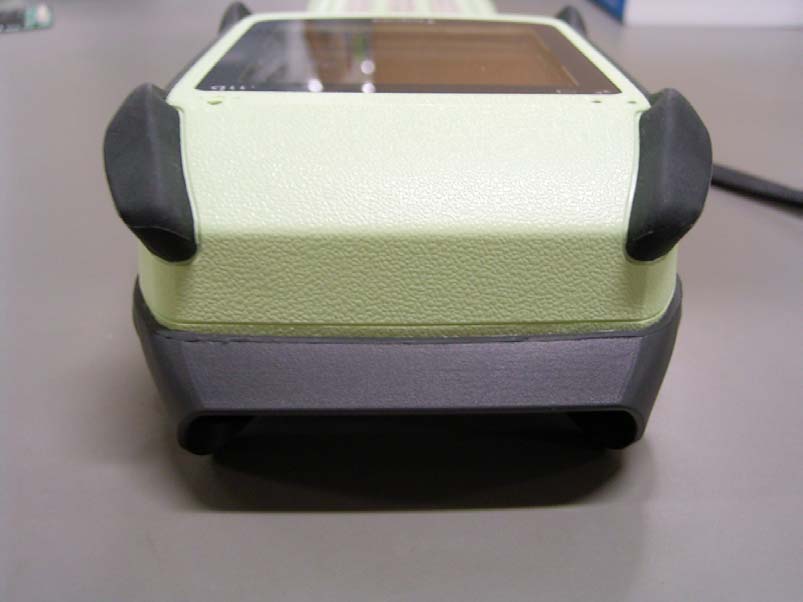
External Photo FURUNO SYSTEMS CO.,LTD. Handy Terminal [PI-13500-W] FCC ID: T87SS23BTXXT Front Rear External Photo FURUNO SYSTEMS CO.,LTD. Handy Terminal [PI-13500-W] FCC ID: T87SS23BTXXT Top Bottom External Photo FURUNO SYSTEMS CO.,LTD. Handy Terminal [PI-13500-W] FCC ID: T87SS23BTXXT Right Left
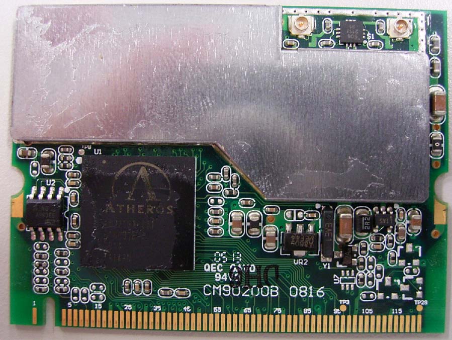
Bluetooth IEEE802.11b Module FCCID Label Position FCCID Label
Internal Photo FURUNO SYSTEMS CO.,LTD. Handy Terminal [PI-13500-W] FCC ID: T87SS23BTXXT Front Rear Internal Photo FURUNO SYSTEMS CO.,LTD. Handy Terminal [PI-13500-W] FCC ID: T87SS23BTXXT Bluetooth Bluetooth (Closeup)
UL Apex Co., Ltd. Head Office EMC Lab. 4383-326 Asama-cho, Ise-shi, Mie-ken 516-0021 JAPAN Telephone : +81 596 24 8116 Facsimile : +81 596 24 8124 Applicant: FURUNO SYSTEMS CO., LTD. Type of Equipment : Handy Terminal Model No. : PI-13500-W FCC ID: T87SS23BTXXT FURUNO SYSTEMS CO., LTD. declares that Model : PI-13500-W complies with FCC radiation exposure requirement specified in the FCC Rules 2.1093(for portable)/2.1091 (for mobile). The “PI-13500-W“ has 0.45 mW of conducted Peak Output power and 0.29 mW of EIRP. This kind of equipment is below 60/frequency[GHz] mW(TCB Exclusion List) so that SAR testing is excluded. The Following calculation is the reference data for 20cm distance. RF Exposure Calculations: The following information provides the minimum separation distance for the highest gain antenna provided with the “PI-13500-W“ as calculate d from FCC OET Bulletin 65 Appendix A, Table (B) Limits for General Population / Uncontrolled Exposure. This calculation is based on the highest EIRP possible from the system, considering maximum power and antenna gain, and considering a 1.0mW/cm^2 uncontrolled exposure limit. The Friis formula used was: S = (P * G) / (4* π * r 2 ) Where P = 0.45 mW (Maximum peak output power) G = 0.63 Numerical Antenna gain; equal -2.00 dBi r =20.0 cm For: PI-13500-WS = 0.00006 mW/cm 2 No. : 26GE0204-HO RF Exposure Statement *Regarding RF Exposure for EUT itself, please refer to UL Apex Test Report No. 26GE0204-HO-C.
Test report No. : 26GE0204-HO-B Page : 2 of 34 Issued date : June 30, 2006 FCC ID : T87SS23BTXXT UL Apex Co., Ltd. Head Office EMC Lab. 4383-326 Asama-cho, Ise-shi, Mie-ken 516-0021 JAPAN Telephone : +81 596 24 8116 Facsimile : +81 596 24 8124 MF060b(14.06.06) CONTENTS PAGE SECTION 1: Client information .............................................................................................................3 SECTION 2: Equipment under test (E.U.T.).........................................................................................3 SECTION 3: Test specification, procedures & results..........................................................................4 SECTION 4: Operation of E.U.T. during testing ..................................................................................7 SECTION 5: Spurious Emission.............................................................................................................8 SECTION 6: Bandwidth ..........................................................................................................................9 SECTION 7: Maximum Peak Output Power ........................................................................................9 SECTION 8: Carrier Frequency Separation .........................................................................................9 SECTION 9: Number of Hopping Frequency .......................................................................................9 SECTION 10: Dwell time.........................................................................................................................9 APPENDIX 1: Photographs of test setup .............................................................................................10 Spurious Emission (Radiated) ...................................................................................... 10 Worst Case Position (Horizontal: X-axis/ Vertical:Y-axis) ....................................... 11 APPENDIX 2:Test instruments .............................................................................................................12 APPENDIX 3: Data of EMI test.............................................................................................................13 Carrier Frequency Separation...................................................................................... 13 20dB Bandwidth............................................................................................................. 15 Number of Hopping Frequency .................................................................................... 17 Dwell time ....................................................................................................................... 19 Maximum Peak Output Power ..................................................................................... 22 Radiated Spurious Emission ......................................................................................... 24 Conducted Spurious Emission ...................................................................................... 30 99% Occupied Bandwidth ............................................................................................ 34 Test report No. : 26GE0204-HO-B Page : 3 of 34 Issued date : June 30, 2006 FCC ID : T87SS23BTXXT UL Apex Co., Ltd. Head Office EMC Lab. 4383-326 Asama-cho, Ise-shi, Mie-ken 516-0021 JAPAN Telephone : +81 596 24 8116 Facsimile : +81 596 24 8124 MF060b(14.06.06) SECTION 1: Client information Company Name : FURUNO SYSTEMS CO.,LTD. Address : 9-52, Ashihara-town, Nishinomiya-city, Hyogo, 662-8580, JAPAN Telephone Number : +81-798-63-1194 Facsimile Number : +81-798-63-1197 Contact Person : Takeaki Okamoto SECTION 2: Equipment under test (E.U.T.) 2.1 Identification of E.U.T. Type of Equipment : Handy Terminal Model No. : PI-13500-W Serial No. : 7038-6346 for Antenna Terminal Conducted test 7038-6350 for Radiated Spurious Emission test Country of Manufacture : Japan Rating : Li-ion Battery: DC3.7V 1800mAh Receipt Date of Sample : February 21, 2006 Condition of EUT : Production model Modification of EUT : No modification by the test lab. 2.2 Product Description Model No: PI-13500-W is the Handy Terminal. PI-13500-W has a variant model No. PI-13503-W, and the difference between the two models is the scanning function (PI-13500-W= one-dimensional scanning, PI-13503-W=two-dimensional scanning). There is no difference in radio specification between these models. Clock frequency(ies) in the system : Bus:29.4912MHz, CPU_INT(Max):117.9648MHz Equipment Type : Barcode scanner built in the head of the body reads a wide variety of barcodes. The compact body houses a large LCD panel, laser scanner, Bluetooth and 802.11b transceiver. Frequency of Operation : 2402-2480MHz Bandwidth & Channel spacing : 1MHz & 1MHz Modulation : FHSS Method of Frequency Generation : Synthesizer Power Supply (inner) : DC 3.3V Antenna Type : Pattern Antenna Antenna Gain : -2 dBi * The EUT contains FCC Granted WLAN module (Model No.:ATC-BICF, FCC ID: T87SS22BXXXM) inside. The WLAN module and Bluetooth module do not transmit simultaneously. Test report No. : 26GE0204-HO-B Page : 4 of 34 Issued date : June 30, 2006 FCC ID : T87SS23BTXXT UL Apex Co., Ltd. Head Office EMC Lab. 4383-326 Asama-cho, Ise-shi, Mie-ken 516-0021 JAPAN Telephone : +81 596 24 8116 Facsimile : +81 596 24 8124 MF060b(14.06.06) SECTION 3: Test specification, procedures & results 3.1 Test Specification Test Specification : FCC Part15 Subpart C: 2006 Title : FCC 47CFR Part15 Radio Frequency Device Subpart C Intentional Radiators Section 15.207 Conducted limits: 2006 Section 15.247 Operation within the bands 902-928MHz, 2400-2483.5MHz, and 5725-5850MHz: 2006 FCC 15.31 (e) The stable voltage (DC3.3V) is supplied with the radio part of the EUT. Therefore, the EUT complies with the requirement. FCC Part 15.203 Antenna requirement It is impossible for end users to replace the antenna, because the antenna is mounted…
Text truncated - open the document above for the full version.
Test report No. : 26GE0204-HO-B Page : 12 of 34 Issued date : June 30, 2006 FCC ID : T87SS23BTXXT UL Apex Co., Ltd. Head Office EMC Lab. 4383-326 Asama-cho, Ise-shi, Mie-ken 516-0021 JAPAN Telephone : +81 596 24 8116 Facsimile : +81 596 24 8124 MF060b(14.06.06) APPENDIX 2:Test instruments EMI test equipment Control No. Instrument Manufacturer Model No Test Item Calibration Date * Interval(month) MSA-03 Spectrum Analyzer Agilent E4448A AT 2005/09/16 * 12 MCC-22 Microwave Cable 1G- 50GHz Storm 421-011 ( 90- 011-080 ) AT 2005/04/29 * 12 MOS-03 Digital Humidity Indicator N.T NT-1800 AT 2004/11/25 * 24 MAEC-02 Anechoic Chamber TDK Semi Anechoic Chamber 3m RE 2005/04/11 * 12 MCC-16 Microwave Cable 1G- 26.5GHz Suhner SUCOFLEX 104 RE 2006/02/02 * 12 MCC-47 Microwave Cable 1G- 26.5GHz Suhner SUCOFLEX1 04 RE 2005/08/30 * 12 MPA-10 Pre Amplifier Agilent 8449B RE 2005/09/07 * 12 MHA-06 Horn Antenna Schwarzbeck BBHA9120D RE 2006/01/09 * 12 MHA-01 Horn Antenna EMCO 3160-09 RE 2006/01/09 * 12 MRENT-23 Spectrum Analyzer Advantest R3273 RE 2006/01/10 * 12 MCC-12 Coaxial Cable Fujikura/Agilent - RE 2005/02/24 * 12 MAT-07 Attenuator(6dB) Weinschel Corp 2 RE 2005/12/16 * 12 MTR-02 Test Receiver Rohde & Schwarz ESCS30 RE 2006/02/02 * 12 MPA-09 Pre Amplifier Agilent 8447D RE 2005/09/07 * 12 MBA-02 Biconical Antenna Schwarzbeck BBA9106 RE 2005/10/10 * 12 MLA-02 Logperiodic Antenna Schwarzbeck USLP9143 RE 2005/10/14 * 12 MOS-02 Digital Humidity Indicator N.T NT-1800 RE 2004/11/25 * 24 MAT-21 Attenuator(20dB)(abov e1GHz) HIROSE ELECTRIC CO.,LTD. AT-120 AT 2006/01/10 * 12 MHA-02 Horn Antenna EMCO 3160-09 RE(MW) 2006/01/09 * 12 MCC-25 Microwave Cable 1G- 26.5GHz Suhner SUCOFLEX1 04 RE 2005/08/30 * 12 MPSE-03 Power sensor Agilent E9327A AT 2005/11/23 * 12 MPM-03 Power Meter Rohde & Schwarz NRVD AT 2005/07/22 * 36 All equipment is calibrated with traceable calibrations. Each calibration is traceable to the national or international standards. Test Item: RE: Radiated Emission test AT: Antenna Terminal Conducted test Test report No. : 26GE0204-HO-B Page : 13 of 34 Issued date : June 30, 2006 FCC ID : T87SS23BTXXT UL Apex Co., Ltd. Head Office EMC Lab. 4383-326 Asama-cho, Ise-shi, Mie-ken 516-0021 JAPAN Telephone : +81 596 24 8116 Facsimile : +81 596 24 8124 MF060b(14.06.06) APPENDIX 3: Data of EMI test Carrier Frequency Separation UL Apex Co., Ltd. Head Office EMC Lab. No.3 Shielded Room COMPANY : FURUNO SYSTEMS CO., LTD.REGULATION : FCC Part15 Subpart C 15.247(a)(1) EQUIPMENT : Handy TerminalTEST DISTANCE : - MODEL : PI13500-WDATE : 02/21/2006 S/ N : 7038-6346TEMPERATURE : 24deg.C POWER : Battery DC3.7VHUMIDITY : 33% MODE : Tx(Hopping on)/InquiryENGINEER : Yutaka Yoshida ChFreq. [MHz] Low2402.0 Mid2441.0 High2480.0 Inquiry2441.0 0.995 2.008 >two-thirds of the 20dB Bandwidth or 25[kHz](whichever is greater) >two-thirds of the 20dB Bandwidth or 25[kHz](whichever is greater) 1.010 1.000 >two-thirds of the 20dB Bandwidth or 25[kHz](whichever is greater) >two-thirds of the 20dB Bandwidth or 25[kHz](whichever is greater) [MHz] Channel separation Limit Test report No. : 26GE0204-HO-B Page : 14 of 34 Issued date : June 30, 2006 FCC ID : T87SS23BTXXT UL Apex Co., Ltd. Head Office EMC Lab. 4383-326 Asama-cho, Ise-shi, Mie-ken 516-0021 JAPAN Telephone : +81 596 24 8116 Facsimile : +81 596 24 8124 MF060b(14.06.06) Carrier Frequency Separation Ch:Low Ch:Mid Ch:High Inquiry Test report No. : 26GE0204-HO-B Page : 15 of 34 Issued date : June 30, 2006 FCC ID : T87SS23BTXXT UL Apex Co., Ltd. Head Office EMC Lab. 4383-326 Asama-cho, Ise-shi, Mie-ken 516-0021 JAPAN Telephone : +81 596 24 8116 Facsimile : +81 596 24 8124 MF060b(14.06.06) 20dB Bandwidth UL Apex Co., Ltd. Head Office EMC Lab. No.3 Shielded Room COMPANY : FURUNO SYSTEMS CO., LTD.REGULATION : FCC Part15 Subpart C 15.247(a)(1) EQUIPMENT : Handy TerminalTEST DISTANCE : - MODEL : PI13500-WDATE : 02/21/2006 S/ N : 7038-6346TEMPERATURE : 24deg.C POWER : Battery DC3.7VHUMIDITY : 33% MODE : Tx (Hopping off) /InquiryENGINEER : Yutaka Yoshida ChFreq.Limit [MHz][MHz] Low2402.0- Mid2441.0- High2480.0- Inquiry2441.0-0.775 0.794 [MHz] 0.846 0.793 20dB Bandwidth Test report No. : 26GE0204-HO-B Page : 16 of 34 Issued date : June 30, 2006 FCC ID : T87SS23BTXXT UL Apex Co., Ltd. Head Office EMC Lab. 4383-326 Asama-cho, Ise-shi, Mie-ken 516-0021 JAPAN Telephone : +81 596 24 8116 Facsimile : +81 596 24 8124 MF060b(14.06.06) 20dB Bandwidth Ch:Low Ch:Mid Ch:High Inquiry Test report No. : 26GE0204-HO-B Page : 17 of 34 Issued date : June 30, 2006 FCC ID : T87SS23BTXXT UL Apex Co., Ltd. Head Office EMC Lab. 4383-326 Asama-cho, Ise-shi, Mie-ken 516-0021 JAPAN Telephone : +81 596 24 8116 Facsimile : +81 596 24 8124 MF060b(14.06.06) Number of Hopping Frequency UL Apex Co., Ltd. Head Office EMC Lab. No.3 Shielded Room COMPANY : FURUNO SYSTEMS CO., LTD.REGULATION : FCC Part15 Subpart C 15.247(a)(1)(iii) EQUIPMENT : Handy TerminalTEST DISTANCE : - MODEL : PI13500-WDATE : 02/21/2006 S/ N : 7038-6346TEMPERATURE : 24deg.C POWER : Battery DC3.7VHUMIDITY : 33% MODE : Tx (Hopping on) /InquiryENGINEER : Yutaka Yoshida ModeLimit [time] Tx(Hoppng on) ≧ 15 ModeLimit [time] Inquiry≧15 [time] 32 [time] 79 Number of channel Number of channel Test report No. : 26GE0204-HO-B Page : 18 of 34 Issued date : June 30, 2006 FCC ID : T87SS23BTXXT UL Apex Co., Ltd. Head Office EMC Lab. 4383-326 Asama-cho, Ise-shi, Mie-ken 516-0021 JAPAN Telephone : +81 596 24 8116 Facsimile : +81 596 24 8124 MF060b(14.06.06) Number of Hopping Frequency Hopping on (1/3) Hopping…
Text truncated - open the document above for the full version.
4383-326 Asama-cho · Ise-shi, Mie-ken · Japan
| # | Rule Parts | Frequency Range | Power Output |
|---|---|---|---|
| 1 | 15C | 2.40 GHz - 2.48 GHz | 450.00 µW |

Digital Transmission System
Equipment Class
DTS - Digital Transmission System