T9A-PADWLNAWLNB-AN-DP101 in PAD 3500
ADASA Inc.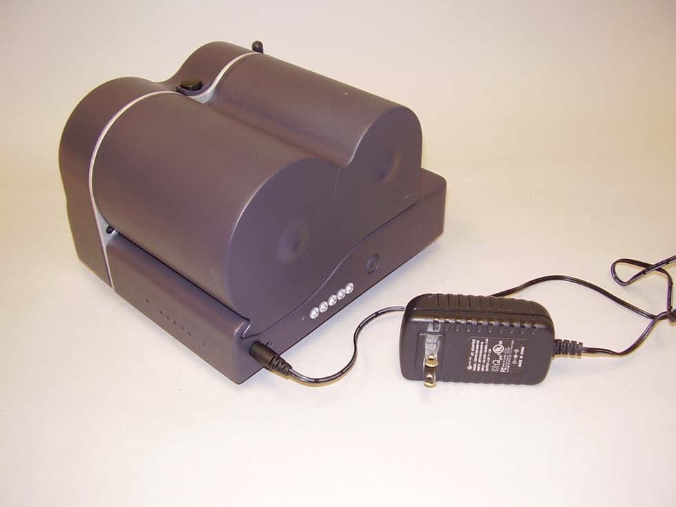
Click to zoom
Application Details
- Equipment Class
- DTS - Digital Transmission System
- Date of Grant
- Jul 10, 2006
- Application Purpose
- Original Equipment
- Date of Application
- Jul 10, 2006
- Equipment Note
- WLNB-AN-DP101 in PAD 3500
- Frequency Range
- 2412.00000000 - 2462.00000000
- Company
- ADASA Inc.
- Country
- United States
Documents & Files
Document Text
Text extracted from the exhibit documents filed with the FCC. Open a document above to read the original.
Users Manual
ADASA PAD3500 Operations Manual ADASA Confidential 1 ALL RIGHTS RESERVED. ADASA, The ADASA Logo, PAD3500 and SmartCartridge are trademarks of ADASA Inc. All other trademarks used in this document are the property of their respective owners. Disclaimer The information in the document is believed to be correct at the time of print. The reader remains responsible for the system usage and for ensuring that the overall system satisfies its design objectives taking due account of the information presented herein, the specifications of other associated equipment environment. ADASA ® Inc. has made commercially reasonable efforts to ensure that the information contained in this document is accurate and reliable. However, the information is subject to change without notice. No responsibility is assumed by ADASA Inc. for the use of the information, nor for infringements of patents or other rights of third parties. This document is the property of ADASA Inc.. and does not imply license under patents, copyrights or trade secrets. NOTE: This equipment has been tested and found to comply with the limits for a Class A digital device, pursuant to part 15 of the FCC Rules. These limits are designed to provide reasonable protection against harmful interference when the equipment is operated in a commercial environment. This equipment generates, uses, and can radiate radio frequency energy and, if not installed and used in accordance with the instruction manual, may cause harmful interference to radio communications. Operation of this equipment in a residential area is likely to cause harmful interference in which case the user will be required to correct the interference at his own expense. Changes or modifications not expressly approved by ADASA Inc. could void the user's authority to operate the equipment. Corporate Headquarters ADASA Inc. PO Box 2689 Eugene, OR 97402 USA Telephone: 541-359-1677 Fax: 541-465-2232 Technical Support: 541-359-1677x301 [email protected] Web Site: www.adasainc.com 2 3 CONTENTS CHAPTER 1 INTRODUCTION ........................................................................................ 5 1.1 O VERVIEW .................................................................................................................................... 5 1.2 FEATURES......................................................................................................................................5 1.3 SMARTCARTRIDGE.......................................................................................................................... 5 1.4 APPLICATIONS ................................................................................................................................6 1.5 CONVENTIONS.................................................................................................................................6 1.5.1 Terminology.......................................................................................................................... 6 1.5.2 Notes .................................................................................................................................... 6 1.5.3 Cautions ............................................................................................................................... 7 1.5.4 Courier Typeface................................................................................................................... 7 CHAPTER 2 PAD3500 Operations Overview ................................................................ 8 CHAPTER 3 PAD3500 Wireless LAN ............................................................................. 14 3.1 O VERVIEW ..................................................................................................................................... 14 3.2 SPECIFICATIONS...............................................................................................................................14 3.3 BLOCK DIAGRAM ............................................................................................................................ 15 3.4 H ARDWARE DESCRIPTION ................................................................................................................15 3.4.1 Application Processor ............................................................................................................... 15 3.4.2 General Purpose Input/Output .................................................................................................. 15 3.4.3 Static Random Access Memory..................................................................................................15 3.4.4 Flash Memory.............................................................................................................................15 3.4.5 IEEE 802.11 Media Access Control............................................................................................16 3.4.6 IEEE 802.11 Baseband/RF.........................................................................................................16 CHAPTER 4 WEB INTERFACE..........................................................................................17 4.1 O VERVIEW ........................................................................................................................................ 17 4.2 ACCESSING THE WEB INTERFACE....................................................................................................... 17 4.3 NAVIGATING THROUGH THE WEB INTERFACE....................................................................................... 18 4.4 STATUS PAGE ................................................................................................................................... 19 4.5 S ERIAL INTERFACE CONFIGURATION PAGE ......................................................................................... 19 4.6 NETWORK SERVICES CONFIGURATION PAGE .......................................................…
Text truncated - open the document above for the full version.
Cover Letter(s)
16 May 2006 Federal Communications Commission Authorization and Evaluation Division 7435 Oakland Mills Road Columbia, Maryland 21046 To whom it may concern, We, the undersigned, hereby authorize Northwest EMC, Inc., to act on our behalf, as our agent, in the following matters related to the FCC approval of our products: report submittal, related correspondence, the signing of all documents relating to these matters, and any other lawful activity necessary to obtain such certification. Any act carried out by Northwest EMC, Inc. within the scope of this authorization shall have the same affect as our own. This authorization shall expire 12 months from original date. Sincerely, Clarke McAllister President
Cover Letter(s)
NORTHWEST EMC, INC. 22975 NW Evergreen Parkway, Suite 400 Hillsboro, OR 97124 June 21, 2006 Dear Application Examiner: On behalf of Adasa, Northwest EMC Inc is submitting this application for the certification of Adasa's Model WLNB-AN-DP101 802.11 WLAN radio module, FCC ID: T9A-PADWLNA. The WLAN radio is installed in Adasa's PAD 3500. The PAD 3500 program tags on a roll as they are incremented. The 802.11(b) radio operates in the 2400-2483.5 MHz band at a single data rate, 2Mbps. The unit is indirectly connected to the AC mains. The radio is co-located with a model M8S RFID reader/programmer. The PAD 3500 is considered a portable device and has received SAR testing. The radio utilizes a Nearson 2.4 GHz Swivel antenna, 131 series. The antenna has a gain of +2 dBi. This configuration satisfies the requirements of 47 CFR 15.203. The receiver portion of this radio transceiver has been verified to FCC Part 15 Class A. The technical reports and exhibits demonstrate compliance with FCC rules 47 CFR 15.247 as a DSSS transmitter. Your efforts in reviewing this application are greatly appreciated. Best regards, Northwest EMC, Inc.
Cover Letter(s)
20 June 2006 Federal Communications Commission Authorization and Evaluation Division 7435 Oakland Mills Road Columbia, Maryland 21046 To whom it may concern, We hereby respectfully request that under the provision of 47 CFR 0.459, the documents listed below and attached with this application for certification be provided with confidential status. • All Schematics • All Operational Descriptions • All Block Diagrams Any exhibit / information for which we have requested confidentiality, but which may not be accorded such treatment by the FCC, should be returned to us. The documents listed above contain trade secrets that are treated as confidential by us. Substantial competitive harm to us could result should they be made available to the public. Sincerely, Clarke McAllister President
Cover Letter(s)
NORTHWEST EMC, INC. 22975 NW Evergreen Parkway, Suite 400 Hillsboro, OR 97124 May 25, 2006 Dear Application Examiner: Adasa's 802.11(b) WLAN radio module, FCC ID: T9A-PADWLNA, is seeking limited modular approval. The radio meets the requirements for limited modular approval as detailed in FCC Public Notice DA00-1407. Compliance to each of the requirements is described below: 1. "The modular transmitter must have its own RF shielding." The radio portion of the module is contained in its own RF shielding. The shielding is installed at the manufacturer's, DPAC Technologies, factory. Please see the Internal Photos exhibit. 2. "The modular transmitter must have buffered modulation/data inputs." The EUT has buffered data inputs to insure compliance with Part 15 requirements under conditions of excessive data rates or over-modulation. Please see the Schematics exhibit. 3. "The modular transmitter must have its own power supply regulation." The EUT has its own power supply regulation to insure compliance with Part 15 requirements regardless of the quality or level of external DC supplying the module from the host unit. Please see the Schematics exhibit. 4. "The modular transmitter must comply with the antenna requirements of Section 15.203 and 15.204(c)." The EUT meets the FCC antenna requirements. Please see Antenna Information exhibit and Internal Photos exhibit. 5. "The modular transmitter must be tested in a stand-alone configuration." The EUT was not tested in a stand-alone configuration. The module was installed in Adasa's PAD 3500. This is why Adasa is seeking limited modular approval of the 802.11 radio module in this host-specific configuration. 6. "The modular transmitter must be labeled with its own FCC ID number." The EUT is not labeled with its own FCC ID number since it will always be factory installed into the PAD 3500. The exterior of the PAD 3500 is labeled with the EUT's FCC ID number. Please see FCC ID label & location exhibit. 7. "The modular transmitter must comply with any specific rule or operating requirements applicable to the transmitter and the manufacturer must provide adequate instructions along with the module to explain any such requirements." The EUT is compliant with all applicable FCC rules. Detailed instructions for maintaining compliance are given in the User Manual. 8. The modular transmitter must comply with any applicable RF exposure requirements." The EUT is compliant with all applicable RF exposure requirements. Please see the SAR Report and the User Manual. Please contact us if you have additional questions. Your attention to this matter is greatly appreciated. Best regards, Northwest EMC, Inc.
Cover Letter(s)
Northwest EMC TCB Compliance Opinion Rev. 9/15/03 ELET0003 Information about the Applicant Company Name Adasa, Inc. Grantee Clarke McAllister Address PO Box 2689 City, State, Zip Eugene, OR 97402 Job Number ELET0003 Model WLNB-AN-DP101 in PAD 3500 FCC ID T9A-PADWLNA Agent Northwest EMC Approval Type Original Equipment Class DSS Part 15 Spread Spectrum Transmitter Rule Part 15.247 Overview Application for Limited Modular approval: Adasa's 802.11 WLAN radio module, FCC ID: T9A- PADWLNA. The WLAN radio is installed in Adasa's PAD 3500. The 802.11(b) radio operates in the 2400-2483.5 MHz band at a single data rate, 2Mbps. The radio is co-located with an RFID reader/programmer. The PAD 3500 is considered a portable device and has received SAR testing. The radio utilizes a Nearson 2.4 GHz Swivel antenna, 131 series. The antenna has a gain of +2 dBi. This configuration satisfies the requirements of 47 CFR 15.203. Recommendation All items have been resolved and completed to my satisfaction; therefore I recommend this application for approval. Signature 7/11/2006 Dave Tolman, TCB Committee
RF Exposure Info
Date/Time: 6/7/2006 11:27:45 AM Test Laboratory: Compliance Certification Services System Performance Check @ 2450 MHz DUT: Dipole 2450 MHz; Type: D2450V2; Serial: D2450V2 - SN:706 Communication System: CW - 2450 MHz; Frequency: 2450 MHz;Duty Cycle: 1:1 Medium parameters used: f = 2450 MHz; σ = 2.03 mho/m; ε r = 51.9; ρ = 1000 kg/m 3 Phantom section: Flat Section Room Ambient Temperature: 23.0deg. C; Liquid Temperature: 22.0 deg. C DASY4 Configuration: - Area Scan setting - Find Secondary Maximum Within: 2.0 dB and with a peak SAR value greater than 0.0012W/kg - Probe: EX3DV4 - SN3552; ConvF(7.08, 7.08, 7.08); Calibrated: 5/30/2006 - Sensor-Surface: 4mm (Mechanical Surface Detection) - Electronics: DAE4 SN558; Calibrated: 1/20/2006 - Phantom: SAM 1; Type: SAM 1; Serial: 1185 - Measurement SW: DASY4, V4.7 Build 21; Postprocessing SW: SEMCAD, V1.8 Build 170 d=10mm, Pin=250mW/Area Scan (7x7x1): Measurement grid: dx=15mm, dy=15mm Maximum value of SAR (measured) = 13.3 mW/g d=10mm, Pin=250mW/Zoom Scan (5x5x7)/Cube 0: Measurement grid: dx=7.5mm, dy=7.5mm, dz=5mm Reference Value = 81.1 V/m; Power Drift = 0.137 dB Peak SAR (extrapolated) = 27.3 W/kg SAR(1 g) = 13 mW/g; SAR(10 g) = 5.93 mW/g Maximum value of SAR (measured) = 14.3 mW/g 0 dB = 14.3mW/g Date/Time: 6/7/2006 11:53:23 AM Test Laboratory: Compliance Certification Services System Performance Check @ 2450 MHz DUT: Dipole 2450 MHz; Type: D2450V2; Serial: D2450V2 - SN:706 Communication System: CW - 2450 MHz; Frequency: 2450 MHz;Duty Cycle: 1:1 d=10mm, Pin=250mW/Z Scan (1x1x41): Measurement grid: dx=20mm, dy=20mm, dz=2.5mm Maximum value of SAR (measured) = 7.16 mW/g
RF Exposure Info
Date/Time: 6/7/2006 1:54:44 PM Test Laboratory: Compliance Certification Services PAD 3500 DUT: PAD 3500; Type: Portable Applicator Device; Serial: N/A Communication System: 802.11bg; Frequency: 2437 MHz;Duty Cycle: 1:1 Medium parameters used (interpolated): f = 2437 MHz; σ = 2.01 mho/m; ε r = 51.9; ρ = 1000 kg/m 3 Phantom section: Flat Section Room Ambient Temperature: 23.0deg. C; Liquid Temperature: 22.0 deg. C DASY4 Configuration: - Area Scan setting - Find Secondary Maximum Within: 2.0 dB and with a peak SAR value greater than 0.0012W/kg - Probe: EX3DV4 - SN3552; ConvF(7.08, 7.08, 7.08); Calibrated: 5/30/2006 - Sensor-Surface: 4mm (Mechanical Surface Detection) - Electronics: DAE4 SN558; Calibrated: 1/20/2006 - Phantom: SAM 1; Type: SAM 1; Serial: 1185 - Measurement SW: DASY4, V4.7 Build 21; Postprocessing SW: SEMCAD, V1.8 Build 170 Antenna Position 1-M ch/Area Scan (11x15x1): Measurement grid: dx=15mm, dy=15mm Info: Interpolated medium parameters used for SAR evaluation. Maximum value of SAR (measured) = 0.138 mW/g Antenna Position 1-M ch/Zoom Scan (5x5x7)/Cube 0: Measurement grid: dx=7.5mm, dy=7.5mm, dz=5mm Reference Value = 1.60 V/m; Power Drift = 0.178 dB Peak SAR (extrapolated) = 0.222 W/kg SAR(1 g) = 0.125 mW/g; SAR(10 g) = 0.069 mW/g Info: Interpolated medium parameters used for SAR evaluation. Maximum value of SAR (measured) = 0.136 mW/g Date/Time: 6/7/2006 3:15:38 PM Test Laboratory: Compliance Certification Services PAD 3500 DUT: PAD 3500; Type: Portable Applicator Device; Serial: N/A Communication System: 802.11bg; Frequency: 2412 MHz;Duty Cycle: 1:1 Medium parameters used (interpolated): f = 2412 MHz; σ = 1.98 mho/m; ε r = 52; ρ = 1000 kg/m 3 Phantom section: Flat Section Room Ambient Temperature: 23.0deg. C; Liquid Temperature: 22.0 deg. C DASY4 Configuration: - Area Scan setting - Find Secondary Maximum Within: 2.0 dB and with a peak SAR value greater than 0.0012W/kg - Probe: EX3DV4 - SN3552; ConvF(7.08, 7.08, 7.08); Calibrated: 5/30/2006 - Sensor-Surface: 4mm (Mechanical Surface Detection) - Electronics: DAE4 SN558; Calibrated: 1/20/2006 - Phantom: SAM 1; Type: SAM 1; Serial: 1185 - Measurement SW: DASY4, V4.7 Build 21; Postprocessing SW: SEMCAD, V1.8 Build 170 Antenna Position 2-L ch/Area Scan (7x7x1): Measurement grid: dx=15mm, dy=15mm Info: Interpolated medium parameters used for SAR evaluation. Maximum value of SAR (measured) = 0.167 mW/g Antenna Position 2-L ch/Zoom Scan (5x5x7)/Cube 0: Measurement grid: dx=7.5mm, dy=7.5mm, dz=5mm Reference Value = 8.97 V/m; Power Drift = 0.179 dB Peak SAR (extrapolated) = 0.308 W/kg SAR(1 g) = 0.157 mW/g; SAR(10 g) = 0.081 mW/g Info: Interpolated medium parameters used for SAR evaluation. Maximum value of SAR (measured) = 0.165 mW/g Date/Time: 6/7/2006 2:22:25 PM Test Laboratory: Compliance Certification Services PAD 3500 DUT: PAD 3500; Type: Portable Applicator Device; Serial: N/A Communication System: 802.11bg; Frequency: 2437 MHz;Duty Cycle: 1:1 Medium parameters used (interpolated): f = 2437 MHz; σ = 2.01 mho/m; ε r = 51.9; ρ = 1000 kg/m 3 Phantom section: Flat Section Room Ambient Temperature: 23.0deg. C; Liquid Temperature: 22.0 deg. C DASY4 Configuration: - Area Scan setting - Find Secondary Maximum Within: 2.0 dB and with a peak SAR value greater than 0.0012W/kg - Probe: EX3DV4 - SN3552; ConvF(7.08, 7.08, 7.08); Calibrated: 5/30/2006 - Sensor-Surface: 4mm (Mechanical Surface Detection) - Electronics: DAE4 SN558; Calibrated: 1/20/2006 - Phantom: SAM 1; Type: SAM 1; Serial: 1185 - Measurement SW: DASY4, V4.7 Build 21; Postprocessing SW: SEMCAD, V1.8 Build 170 Antenna Position 2-M ch/Area Scan (11x15x1): Measurement grid: dx=15mm, dy=15mm Info: Interpolated medium parameters used for SAR evaluation. Maximum value of SAR (measured) = 0.161 mW/g Antenna Position 2-M ch/Zoom Scan (5x5x7)/Cube 0: Measurement grid: dx=7.5mm, dy=7.5mm, dz=5mm Reference Value = 4.81 V/m; Power Drift = -0.185 dB Peak SAR (extrapolated) = 0.296 W/kg SAR(1 g) = 0.153 mW/g; SAR(10 g) = 0.080 mW/g Info: Interpolated medium parameters used for SAR evaluation. Maximum value of SAR (measured) = 0.162 mW/g Date/Time: 6/7/2006 2:42:21 PM Test Laboratory: Compliance Certification Services PAD 3500 DUT: PAD 3500; Type: Portable Applicator Device; Serial: N/A Communication System: 802.11bg; Frequency: 2437 MHz;Duty Cycle: 1:1 Antenna Position 2-M ch/Z Scan (1x1x41): Measurement grid: dx=20mm, dy=20mm, dz=2.5mm Info: Interpolated medium parameters used for SAR evaluation. Maximum value of SAR (measured) = 0.094 mW/g Date/Time: 6/7/2006 3:30:35 PM Test Laboratory: Compliance Certification Services PAD 3500 DUT: PAD 3500; Type: Portable Applicator Device; Serial: N/A Communication System: 802.11bg; Frequency: 2462 MHz;Duty Cycle: 1:1 Medium parameters used (interpolated): f = 2462 MHz; σ = 2.05 mho/m; ε r = 51.9; ρ = 1000 kg/m 3 Phantom section: Flat Section Room Ambient Temperature: 23.0deg. C; Liquid Temperature: 22.0 deg. C DASY4 Configuration: - Area Scan setting - Find Secondary Maximum Within: 2.0 dB and with a peak SAR value greater than 0.0012W/kg - Probe: EX3DV4 - SN3552; ConvF(7.08, 7.08, 7.08); Calibrated: 5/30/2006 - Sensor-Surface: 4mm (Mechanical Surface Detection) - Electronics: DAE4 SN558; Calibrated: 1/20/2006 - Phantom: SAM 1; Type: SAM 1; Serial: 1185 - Measurement SW: DASY4, V4.7 Build 21; Postprocessing SW: SEMCAD, V1.8 Build 170 Antenna Position 2-H ch/Area Scan (7x7x1): Measurement grid: dx=15mm, dy=15mm Info: Interpolated medium parameters used for SAR evaluation. Maximum value of SAR (measured) = 0.124 mW/g Antenna Position 2-H ch/Zoom Scan (5x5x7)/Cube 0: Measurement grid: dx=7.5mm, dy=7.5mm, dz=5mm Reference Value = 7.66 V/m; Power Drift = 0.051 dB Peak SAR (extrapolated) = 0.232 W/kg SAR(1 g) = 0.115 mW/g; SAR(10 g) = 0.060 mW/g Info: Interpolated medium parameters used for SAR evaluation. Maximum value of SAR (measured) = 0.121 mW/g Date/Time: 6/7/2006 4:18:32 PM Test Laboratory: Compliance Certification Services PAD 3500 DUT: PAD 3500…
Text truncated - open the document above for the full version.
RF Exposure Info
IN ACCORDANCE WITH THE REQUIREMENTS OF FCC OET BULLETIN 65 SUPPLEMENT C IC RSS 102 ISSUE 1 : 1999 AUSTRALIAN COMMUNICATIONS AUTHORITY (ACA) STANDARD “RADIOCOMMUNICATIONS (ELECTROMAGNETIC RADIATION-HUMAN EXPOSURE) STANDARD 2003”, SCHEDULE 2 NEW ZEALAND STANDARD NZS 2772: PART 1: 1999 FOR 802.11B MODULE IS INSTALLED IN PORTABLE APPLICATOR DEVICE, PAD 3500 MODEL: WLNB-AN-DP101 FCC ID: T9A-PADWLNA REPORT NUMBER: 06U10354-1C ISSUE DATE: JUNE 20, 2006 Prepared for ADASA INC. PO BOX 2689, EUGENE, OR 97402, USA Prepared by COMPLIANCE CERTIFICATION SERVICES 561F MONTEREY ROAD, MORGAN HILL, CA 95037, USA TEL: (408) 463-0885 REPORT NO: 06U10354-1C DATE: June 20, 2006 FCC ID: T9A-PADWLNA COMPLIANCE CERTIFICATION SERVICES Page: 2 of 26 Revision History Rev. Issued date Revisions Revised By -- June 12, 2006 Initial issue HS B June 15, 2006 Correction of model numbers ND C June 20, 2006 Correction of model numbers ND This report shall not be reproduced except in full, without the written approval of CCS. REPORT NO: 06U10354-1C DATE: June 20, 2006 FCC ID: T9A-PADWLNA COMPLIANCE CERTIFICATION SERVICES Page: 3 of 26 CERTIFICATE OF COMPLIANCE (SAR EVALUATION) DATES OF TEST: June 7, 2006 APPLICANT: ADDRESS: ADASA Inc. PO Box 2689, Eugene, OR 97402, USA FCC ID: MODEL: T9A-PADWLNA WLNB-AN-DP101 DEVICE CATEGORY: EXPOSURE CATEGORY: Prototype Device General Population/Uncontrolled Exposure 802.11b is installed in Portable Applicator Device, PAD 3500 along with ELET0003 RFID FCC ID: T9A- PADRFIDA. Test Sample is a: Prototype Modulation type: Direct Sequence Spread Spectrum (DSSS) for 802.11b Rule Parts Frequency Range [MHz] The Highest SAR Values [mW/g] Collocation SAR Values [mW/g] FCC 15.247 2412 - 2462 1g: 0.160 10g: 0.080 1g: 0.150 10g: 0.076 This wireless portable device has been shown to be capable of compliance for localized specific absorption rate (SAR) for General Population/Uncontrolled Exposure limits specified in ANSI/IEEE Std. C95.1-1992 and had been tested in accordance with the measurement procedures specified in FCC OET 65 Supplement C (Edition 01-01) and RSS 102. This wireless portable device has been shown to be capable of compliance for localized specific absorption rate (SAR) for General Population limits specified in the Australian Radiation Protection and Nuclear Safety Agency (ARPANSA) standard and had been tested in accordance with the measurement procedures specified in Australian Communications Authority (ACA) standard “Radiocommunications (Electromagnetic Radiation-Human Exposure) Standard 2003”, Schedule 1 and Schedule 2 and New Zealand Standard “NZS 2772: Part 1: 1999”. Note: The results documented in this report apply only to the tested sample, under the conditions and modes of operation as described herein. This document may not be altered or revised in any way unless done so by Compliance Certification Services and all revisions are duly noted in the revisions section. Any alteration of this document not carried out by Compliance Certification Services will constitute fraud and shall nullify the document. No part of this report may be used to claim product certification, approval, or endorsement by NVLAP, NIST, or any government agency. Approved & Released For CCS By: Tested By: Hsin Fu Shih Ninous Davoudi Senior Engineer EMC Engineer Compliance Certification Services Compliance Certification Services This report shall not be reproduced except in full, without the written approval of CCS. REPORT NO: 06U10354-1C DATE: June 20, 2006 FCC ID: T9A-PADWLNA COMPLIANCE CERTIFICATION SERVICES Page: 4 of 26 Table Of Contents 1 EQUIPMENT UNDER TEST (EUT) DESCRIPTION............................................................................5 2 FACILITIES AND ACCREDITATION...................................................................................................5 3 SYSTEM DESCRIPTION.....................................................................................................................6 3.1 COMPOSITION OF INGREDIENTS FOR TISSUE SIMULATIG LIQUIDS.................................7 4 SIMULATING LIQUID PARAMETERS CHECK...................................................................................8 4.1 SIMULATING LIQUID PARAMETER CHECK RESULT.............................................................. 9 5 SYSTEM PERFORMANCE CHECK..................................................................................................10 5.1 SYSTEM PERFORMANCE CHECK RESULTS........................................................................11 6 SAR MEASURMENT PROCEDURE.................................................................................................12 6.1 DASY4 SAR MEASURMENT PROCEDURE............................................................................13 7 PROCEDURE USED TO ESTABLISH TEST SIGNAL......................................................................14 8 SAR MEASURMENT RESULTS........................................................................................................15 8.1 ANTENNA POSITION 1.............................................................................................................15 8.2 ANTENNA POSITION 2.............................................................................................................16 8.3 ANTENNA POSITION 3.............................................................................................................17 8.4 ANTENNA POSITION 2 WITH BELT........................................................................................18 9 MEASURMENT UNCERTAINTY.......................................................................................................19 9.1 MEASURMENT UNCERTAINTY FOR 300 MHZ – 3000 MHZ.................................................19 10 EQUIPMENT LIST AND CALIBRATION............................................................................................20 11 PHOTOS.....................................................................................…
Text truncated - open the document above for the full version.
Test Report
Electronic Design Consultants, Inc. WLNB-AN-DP101 radio in PAD 3500 June 09, 2006 Report No. ELET0004 Report Prepared By www.nwemc.com 1-888-EMI-CERT © 2006 Northwest EMC, Inc 22975 NW Evergreen Parkway Suite 400 Hillsboro, Oregon 97124 Certificate of Test Issue Date: June 09, 2006 Electronic Design Consultants, Inc. Model: WLNB-AN-DP101 radio in PAD 3500 Emissions Test Description Specification Test Method Pass Fail Conducted Emissions FCC 15.107 Class B:2005-10 ANSI C63.4:2003 AC Powerline Conducted Emissions FCC 15.207 AC Powerline Conducted Emissions:2005-10 ANSI C63.4:2003 Occupied Bandwidth FCC 15.247(a) Occupied Bandwidth:2006-2 ANSI C63.4:2003 Output Power FCC 15.247(b) Output Power:2006-2 ANSI C63.4:2003 Band Edge Compliance FCC 15.247(d) Band Edge Compliance:2006-2 ANSI C63.4:2003 Spurious Conducted Emissions FCC 15.247(d) Spurious Conducted Emissions:2006-2 ANSI C63.4:2003 Spurious Radiated Emissions FCC 15.247(d) Spurious Radiated Emissions:2006-2 ANSI C63.4:2003 Power Spectral Density FCC 15.247(e) Power Spectral Density:2006-2 ANSI C63.4:2003 Modifications made to the product See the Modifications section of this report Test Facility The measurement facility used to collect the data is located at: Northwest EMC, Inc. 22975 NW Evergreen Parkway, Suite 400; Hillsboro, OR 97124 Phone: (503) 844-4066 Fax: 844-3826 This site has been fully described in a report filed with and accepted by the FCC (Federal Communications Commission) and Industry Canada. Approved By: Greg Kiemel, Director of Engineering This report must not be used to claim product certification, approval, or endorsement by NVLAP, NIST, or any agency of the federal government of the United States of America. Product compliance is the responsibility of the client, therefore the tests and equipment modes of operation represented in this report were agreed upon by the client, prior to testing. This Report may only be duplicated in its entirety. The results of this test pertain only to the sample(s) tested, the specific description is noted in each of the individual sections of the test report supporting this certificate of test. Northwest EMC Revision History Revision 05/05/03 Revision Number Description Date Page Number 00 None Northwest EMC Accreditations and Authorizations Revision 03/18/05 FCC: Accredited by NVLAP for performance of FCC radio, digital, and ISM device testing. Our Open Area Test Sites, certification chambers, and conducted measurement facilities have been fully described in reports filed with the FCC and accepted by the FCC in letters maintained in our files. Northwest EMC has been accredited by ANSI to ISO / IEC Guide 65 as a product certifier. We have been designated by the FCC as a Telecommunications Certification Body (TCB). This allows Northwest EMC to certify transmitters to FCC specifications in accordance with 47 CFR 2.960 and 2.962. NVLAP: Northwest EMC, Inc. is accredited under the United States Department of Commerce, National Institute of Standards and Technology, and National Voluntary Laboratory Accreditation Program for satisfactory compliance with the requirements of ISO/IEC 17025 for Testing Laboratories. The NVLAP accreditation encompasses Electromagnetic Compatibility Testing in accordance with the European Union EMC Directive 89/336/EEC, ANSI C63.4, MIL- STD 461E, DO-160D and SAE J1113. Additionally, Northwest EMC is accredited by NVLAP to perform radio testing in accordance with the European Union R&TTE Directive 1999/5/EEC, the requirements of FCC, and the RSS radio standards for Industry Canada. NVLAP LAB CODE 200629-0 NVLAP LAB CODE 200630-0 NVLAP LAB CODE 200676-0 Industry Canada: Accredited by NVLAP for performance of Industry Canada RSS and ICES testing. Our Open Area Test Sites and certification chambers comply with RSS 212, Issue 1 (Provisional) and have been filed with Industry Canada and accepted. Northwest EMC has been accredited by ANSI to ISO / IEC Guid…
Text truncated - open the document above for the full version.
Contact Information
Applicant
Clarke William McAllister(President)
Test Firm
Northwest EMC, Inc.Greg Kiemel
Technical Specifications
| # | Rule Parts | Frequency Range | Power Output |
|---|---|---|---|
| 1 | 15C | 2.41 GHz - 2.46 GHz | 19.70 mW |
Other Applications from ADASA Inc.
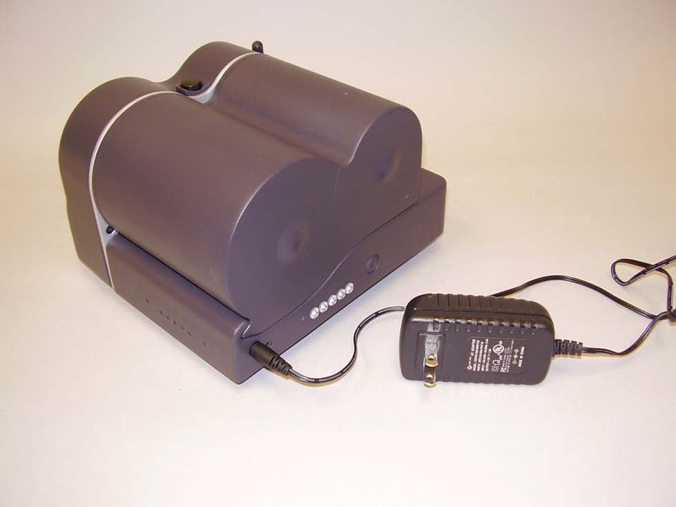
T9A-PADRFIDA
Jul 10, 2006M8S in PAD 3500
Equipment Class
DSS - Part 15 Spread Spectrum Transmitter