T9RHAWKEYEBase Station �Swamp Box unit
Tag Tracking Inc.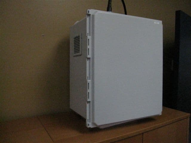
Click to zoom
Application Details
- Equipment Class
- DSS - Part 15 Spread Spectrum Transmitter
- Date of Grant
- Oct 26, 2010
- Application Purpose
- Original Equipment
- Date of Application
- Oct 24, 2010
- Equipment Note
- Base Station �Swamp Box unit
- Frequency Range
- 902.24000000 - 927.76000000
- Company
- Tag Tracking Inc.
- Country
- Canada
Documents & Files
Document Text
Text extracted from the exhibit documents filed with the FCC. Open a document above to read the original.
Users Manual
CONFIDENTIAL & PROPRIETARY BS-SB-1 v.0r1 Base Station The BS-SB-1 base station is an autonomous transceiver that is used primarily for the identification, control and management of assets using RF (radio frequencies). The base station may be used in conjunction with active transponders which may be affixed to assets with which it can communicate in order to collect data. Description of the system; The base station system has been developped with the goal of providing the following services. • Data transfer, logging and Telemetrie • Temperature monitoring • Humidity monitoring • Automated inventory management • Automated fleet management HOUSING Installation guidelines; The base station must be installed by qualified personnel. The housing must be affixed to a solid surface using hardware that is rust resistante. The entire mating surface must be used in order to ensure a solid installation. The housing must be installed (plumb and level). ANTENNA Installation guidelines; The antenna must be installed by qualified personel. Ensure that the antenna is affixed to a stable and plumb mast or pole. The installation must be done using (U-clamps) of the proper size and fit. Ensure that the antenna is fitted to a pole that is porperly grounded. Ensrue that there is sufficient clearance from electrical wires. USER GUIDE • Reinforced • Completely water tight • Long service life • Highly robust communication protocol • Easy to install Using the base staiton; PRIOR to initialization ensure that the base station, antenna and coaxial cable are installed. Upon initialisation the base station will register on the network and create a secure connection to the central server. This is an automated process and require no interaction. 1) Simply power up the unit and observe the L.E.D. indicators. 2) 1 st L.E.D. must be red indicating POWER ON 3) 2 nd L.E.D. must be GREEN (solid) indicating modem link 4) 3 rd L.E.D. must be GREEN (flashing) indicating network activity 5) 4 th L.E.D. must be GREEN (solid) indicating network connection Once you have observed that L.E.D. activity is as per the above guidelines you may now close and lock the enclosure. Ensure that the door and all other oppenings are water tight and locked. UPDATES; 1) Start a communication and update session Using the NIPT (Network Interface & Protocol Terminal). 2) Enter the basestation ID in the connect/setup dialog box and press enter. (automated-handshake) 3) Select the UPDATE operation from the check list and click (execute). This will start an automated update script that will run and complete the update process. 4) Upon completion the GUI will provide a “pop up” indicating that the update has been successfully completed. REMOTE (Re-start / Re-initialization); The Re-start function is used primarily as a preventative measure. A clean Re-start is required in order to flush all of the system buffers. The Re-initialization function is used in order to re-name and change a base station ID. Re-START: 1) Start a communication and update session Using the NIPT (Network Interface & Protocol Terminal). 2) Enter the basestation ID in the connect/setup dialog box and press enter. (automated-handshake) 3) Select the Re-Start operation from the check list and click (execute). This will start an automated re-start script that will run and complete the process. 4) Once the basestation has Re-started it will re-connect with NIPT. The GUI will the provide a “pop up” indicating that the Re-start has been successfully completed. Re-INITIALIZATION: 1) Start a communication and update session Using the NIPT (Network Interface & Protocol Terminal). 2) Enter the basestation ID in the connect/setup dialog box and press enter. (automated-handshake) 3) Select the Re-initialization operation from the check list and click (execute). This will start an automated Re-initialisation script that will run and complete the process. 4) Once the basestation has re-started it will re-connect with NIPT. The GUI will the provide a “pop up” indicating that the Re-initialization has been successfully completed. WARNINGS; • This equipement may only be used and serviced by authorized personnel • Disconnect ALL electrical and coaxial connections to the base station before servicing • Follow all applicable regulatory and safety guidelines when choosing a location • Do not install the base station on semi-rigid surfaces • Do not install the base station on moving structures • Changes or modifications not expressly approved by the party responsible for compliance could void the user's authority to operate the equipment. • This equipment must be professionally installed. • The antenna(s) used for this transmitter must be installed to provide a separation distance of at least 20 cm from the radiating element to any nearby persons. • This device and its antenna must not be co-located or operated in conjunction with any other antenna or transmitter.” • This device has been designed to operate with the antennas listed below, and having a maximum gain of 8 dBi (5.86dBd). Antennas not included in this list or having a gain greater than 8 dBi (5.86dBd) are strictly prohibited for use with this device. The required antenna impedance is 50 ohms. • The cable loss from the antenna terminal on this equipment to the external antenna must greater than or equal to 4 dB. Antenna and RF cable (SPECIFICATIONS): Model # : HGV-906U or HG908U-PRO Manufacturer : L-COM RF Gain : (HG-906U) @ 6dBi (HG-908U-PRO) @ 8dBi RF connector type: Type N female RF Cable type: LMR-400 or LMR-600 RF cable length: (LMR-400) @ 100’ feet (LMR-600) @ 200’ feet Rated RF cable loss: (LMR-400) = 4.25dB @ 100 feet (LMR-600) = 5dB @ 200 feet Technical Specifications General information Operating ratings Dimensions (enclosure) Operating temperature : -40 +85°C Height : 520.70 mm (20.50 inches) Environmental norm : IP66 Width : 413.25 mm (16.27 inches) Length : 257.30 mm (10.13 inches) Specifications (RADIO) Material : Fiberglass reinfo…
Text truncated - open the document above for the full version.
Cover Letter(s)
9 June 2010 Equipment Autorisation Division Federal Communications Commission 7435 Oakland Mills Road Columbia, MD 21046 FCC ID:T9RHAWKEYE Request for Confidentiality Pursuant to Sections 0.457 and 0.459 of the commissions rules, we hereby request that the following documents be held confidential: • Schematics • Block diagram • Operational Description These materials contain trade secrets and proprietary information and are not customarily released to the public. The public disclosure of this information might be harmful to the company and provide unjustified benefits to our competitors. Dated this 16 Day of June 20 10 By: Jason M Gallovich Signature Printed Title: President On behalf of : 4126254 Canada Inc Telephone: 514 745 8241
Cover Letter(s)
4126254 Canada Inc. 5631 Chemin St-François Ville St-Laurent, Québec H4S 1W6 T: +1 (514) 745-8241 F: +1 (514) 745-8630 Thursday July 1 st 2010 From: Mr. Jason M Gallovich (grantee contact) Grantee code: T9R Subject: FCC – Professional installation justification letter This letter is to provide an explanation for (professional installation designation) of equipment model # BS-SB-1 FCC ID: T9RHAWKEYE. This equipment requires the use of an external antenna which must be mounted on high sites. The sites may include towers and or building roof tops. These installations must be performed by professionals who have authorization and training to access and work on or at these locations. Special equipment such as harnesses and rigging must also be used. Therefore it is understood that this equipment is not sold to the general public. It is further understood that the intended use of this equipment is generally not for the general public. It is primarily intended for industrial/commercial use. Installation requires the following; • Installation must be controlled and performed by a professional. • Installer must have climbing and rigging experience when installing in elevated locations or on masts. • Installer must be authorized to gain access to installation sites. Regards, Jason M Gallovich President - 4126254 Canada Inc.
ID Label/Location Info
LABEL REQUIREMENTS RF IC & FCC This is a representation of our label 4126254 Can inc. BS-SB-1 IC: 6519A-HAWKEYE FCC ID: T9RHAWKEYE ||||||||||||||||||||| |||| |||||||||||||||||| |||||||||||||| ||||||||||||||||| || Unit serial identifier and bar code This device complies with Part 15 of the FCC Rules. Operation is subject to the following two conditions: (1) This device may not cause harmful interference, and (2) This device must accept any interference received, including interference that may cause undesired operation. Made in Canada *If label format is not in full scale, please indicate the dimensions of the label. Actual Dimensions: W: 1.500 inches H: 1.000 inches Label placement exhibit : Equipment ID label located on front pannel in the lower right hand corner.
Parts List/Tune Up Info
L-COM, INC. 45 BEECHWOOD DRIVE NORTH ANDOVER, MA 01845 WWW.L-COM.COM E-MAIL: [email protected] PHONE: 1-800-343-1455 FAX: 1-978-689-9484 © L-com, Inc. All Rights Reserved. L-com Global Connectivity and the L-com logo are registered marks. HyperLink Wireless 900 MHz Professional 8 dBi High Performance Omni Antenna for ISM, GSM and Wireless LAN Systems Applications and Features Applications: y 900MHz ISM Band y Wireless LAN systems y Multipoint applications y Non Line of Sight (NLOS) y GSM y SCADA y Wireless Video Links Cellular Band y 900MHz Cellular Band Features: y Superior performance y Rugged industrial grade design y Lightweight fiberglass radome y All weather operation y Integral N-Female connector y Includes heavy-duty steel mast mounting brackets Model: HG908U-PRO Description The HyperGain® HG908U-PRO is a high performance omnidirectional antenna designed for the 900 MHz ISM band. It is ideally suited for multipoint, Non Line of Sight (NLOS) and mobile applications where high gain and wide coverage is desired. Typical applications include 900MHz Wireless LAN, SCADA, Wireless Video Links and 900MHz Cellular band applications. This antenna features an integral N-Female type connector that mounts through the wall of an equipment enclosure. Included with the HG908U-PRO is a dual u-bolt mast mounting kit. Consisting of a heavy-duty steel bracket and a pair of U-bolts, this kit allows installation on masts up to 2.0" in diameter. This omni antenna’s construction features a rugged 1.58" diameter white fiberglass radome for durability, aesthetics and long service life. It is designed for all weather operation. Specifications Electrical Specifications Frequency 900 - 928 MHz Gain 8 dBi Vertical Beam Width 16 degrees Impedance 50 Ohm Max. Input Power 100 Watts VSWR < 1.5:1 avg. L-COM, INC. 45 BEECHWOOD DRIVE NORTH ANDOVER, MA 01845 WWW.L-COM.COM E-MAIL: [email protected] PHONE: 1-800-343-1455 FAX: 1-978-689-9484 © L-com, Inc. All Rights Reserved. L-com Global Connectivity and the L-com logo are registered marks. Mechanical Specifications Connector Integral N-Female Weight 2.8 lbs. (1.3 Kg) Length 47.5 in. (1.2 m) Radome Diameter 1.58 in. (40.1 mm) Base Diameter 1.71 in. (43.4 mm) Radome Material White Fiberglass Mounting 1¼" to 2" dia. mast max. (31.7mm to 50.8mm dia.) Polarization Vertical Operating Temperature -40° C to 85° C (-40° F to 185° F) RoHS Compliant Yes RF Antenna Gain Patterns This product is backed by L-Com's Limited Warranty.
Parts List/Tune Up Info
L-COM, INC. 45 BEECHWOOD DRIVE NORTH ANDOVER, MA 01845 WWW.L-COM.COM E-MAIL: [email protected] PHONE: 1-800-343-1455 FAX: 1-978-689-9484 © L-com, Inc. All Rights Reserved. L-com Global Connectivity and the L-com logo are registered marks. HyperLink Wireless brand 800/900 MHz (824 - 960 MHz) 6 dBi High Performance Omnidirectional Antenna Applications and Features Applications: 900MHz ISM Band Wireless LAN systems Multipoint applications Non Line of Sight (NLOS) GSM SCADA Wireless Video Links 800MHz Cellular Band 900MHz Cellular Band Nextel® Features: Superior performance Rugged industrial grade design Lightweight fiberglass radome All weather operation Integral N-Female connector Heavy-duty steel mounting bracket Includes mast mounting kit Model: HGV-906U Description The HyperGain® HGV-906U is a high performance omnidirectional antenna designed for the 800 MHz / 900 MHz ISM band. It is ideally suited for multipoint, Non Line of Sight (NLOS) and mobile applications where high gain and wide coverage is desired. Typical applications include 900MHz Wireless LAN, SCADA, Wireless Video Links and 800 MHz as well as 900MHz Cellular band applications. This antenna features an integral N-Female bulkhead type connector that mounts through the wall of an equipment enclosure. Included with the HGV-906U is a mast mounting kit. Consisting of a heavy-duty steel bracket and a pair of U-bolts, this kit allows installation on masts up to 2.0" in diameter. This omni antenna’s construction features a rugged 1.3" diameter white high intensity fiberglass radome for durability and aesthetics. It is designed for all weather operation. L-COM, INC. 45 BEECHWOOD DRIVE NORTH ANDOVER, MA 01845 WWW.L-COM.COM E-MAIL: [email protected] PHONE: 1-800-343-1455 FAX: 1-978-689-9484 © L-com, Inc. All Rights Reserved. L-com Global Connectivity and the L-com logo are registered marks. Specifications Electrical Specifications Frequency 824 - 960 MHz Gain 6 dBi Vertical Beam Width 30 degrees Impedance 50 Ohm Max. Input Power 100 Watts VSWR < 1.5:1 avg. Mechanical Specifications Connector Integral N-Female Weight 2.4 lbs. (1.1 Kg) Length 23.6 in. (600 mm) Diameter 1.3 in. (33 mm) Radome Material White Fiberglass Mounting 1¼" to 2" dia. mast max. (31.7mm to 50.8mm dia.) Polarization Vertical Operating Temperature -40° C to to 85° C (-40° F to 185° F) Rated Wind Velocity 108 MPH RoHS Compliant Yes RF Antenna Gain Patterns This product is backed by L-com's Limited Warranty.
RF Exposure Info
Prediction of MPE limit at a given distance Equation from page 18 of OET Bulletin 65, Edition 97-01where: S = power density P = power input to the antennaG = power gain of the antenna in the direction of interest relative to isotropicR = distance to the center of radiation of the antenna Maximum peak output power at antenna input terminal: 30.0 (dBm) Maximum peak output power at antenna input terminal: 1000 (mW) Antenna gain(typical): 8 (dBi) Maximum antenna gain: 6.31 (numeric) Prediction distance: 20 (cm) Cable loss: 4 (dB) Prediction frequency: 902 (MHz) MPE limit for uncontrolled exposure at prediction frequency: 0.60 (mW/cm^2) Power density at prediction frequency: 0.50 (mW/cm^2) Power density at prediction frequency: 5.00 (W/m^2) Margin of Compliance: 0.80 (dB) 2 4 R PG S π =
Test Report
www.nemko.com Report Reference ID: 148744-1TRFWL Test specification: Title 47 - Telecommunication Chapter I - Federal Communications Commission Subchapter A - General Part 15 - Radio Frequency Devices Subpart C - Intentional Radiators §15.247 - Operation within the bands 902–928 MHz, 2400–2483.5 MHz and 5725–5850 MHz Applicant: 4126254 Canada Inc. 5631 St-Francois St-Laurent, QC H4S 1W6 Canada Apparatus: Base station FCC ID: T9RHAWKEYE Model: BS-SB-1 Testing laboratory: Nemko Canada Inc. 303 River Road Ottawa, ON, Canada K1V 1H2 Telephone: (613) 737-9680 Facsimile: (613) 737-9691 Name and title Date Tested by: Andrey Adelberg, Senior Wireless/EMC Specialist April 30, 2010 Reviewed by: Richard Brazeau, Laboratory Manager October 22, 2010 Nemko Canada Inc., a testing laboratory, is accredited by the Standards Council of Canada. The tests included in this report are within the scope of this accreditation. 15.247.doc - Date: April 13, 2010 Product: Base station Nemko Canada Inc., 303 River Rd, Ottawa, ON, Canada, K1V 1H2 Report reference ID: 148744-1TRFWL Page 2 of 29 Table of contents Section 1: Report summary.........................................................................................................................................................3 1.1 Test specification.........................................................................................................................................................3 1.2 Statement of compliance.............................................................................................................................................3 1.3 Exclusions....................................................................................................................................................................3 1.4 Registration number....................................................................................................................................................3 1.5 Test report revision history...........................................................................................................................................3 1.6 Test location................................................................................................................................................................3 1.7 Limits of responsibility..................................................................................................................................................3 Section 2: Summary of test results.............................................................................................................................................4 2.1 General requirements for FCC Part 15 tests result summary......................................................................................4 2.2 FCC Part 15 Subpart C, 15.247 tests result summary.................................................................................................4 Section 3: Equipment under test (EUT) details..........................................................................................................................5 3.1 Sample information......................................................................................................................................................5 3.2 EUT information...........................................................................................................................................................5 3.3 EUT technical specifications........................................................................................................................................6 3.4 Operation of the EUT during testing............................................................................................................................6 3.5 EUT setup diagram......................................................................................................................................................6 Section 4: Engineering considerations.......................................................................................................................................7 4.1 Modifications incorporated in the EUT.........................................................................................................................7 4.2 Technical judgment......................................................................................................................................................7 4.3 Deviations from laboratory tests procedures................................................................................................................7 Section 5: Test conditions...........................................................................................................................................................8 5.1 Power source and ambient temperatures....................................................................................................................8 Section 6: Measurement uncertainty..........................................................................................................................................9 Section 7: Test equipment.........................................................................................................................................................10 7.1 Test equipment list.....................................................................................................................................................10 Section 8: Testing data...............................................................................................................................................................11 8.1 Clause 15.31(e) Variation of power source................................................................................................................11 8.2 Clause 15.31(m) Number of operating frequencies..............................................…
Text truncated - open the document above for the full version.
Contact Information
Applicant
Jason M Gallovich(President)
Technical Contact
4126254 Canada Inc.Simon Noel
[email protected]514-745-8241
5631 St-Francois · St-Laurent, Quebec · Canada
Non-Technical Contact
4126254 Canada Inc.Jason M Gallovich
[email protected]514-745-8241
Test Firm
Nemko Canada Inc. (Ottawa)Charles Neal
Technical Specifications
| # | Rule Parts | Frequency Range | Power Output |
|---|---|---|---|
| 1 | 15C | 902.24 MHz - 927.76 MHz | 1 W |
Other Applications from Tag Tracking Inc.
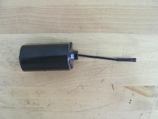
T9RTAGX
Sep 14, 2011Autonomous TAG-Transceiver
Equipment Class
DSS - Part 15 Spread Spectrum Transmitter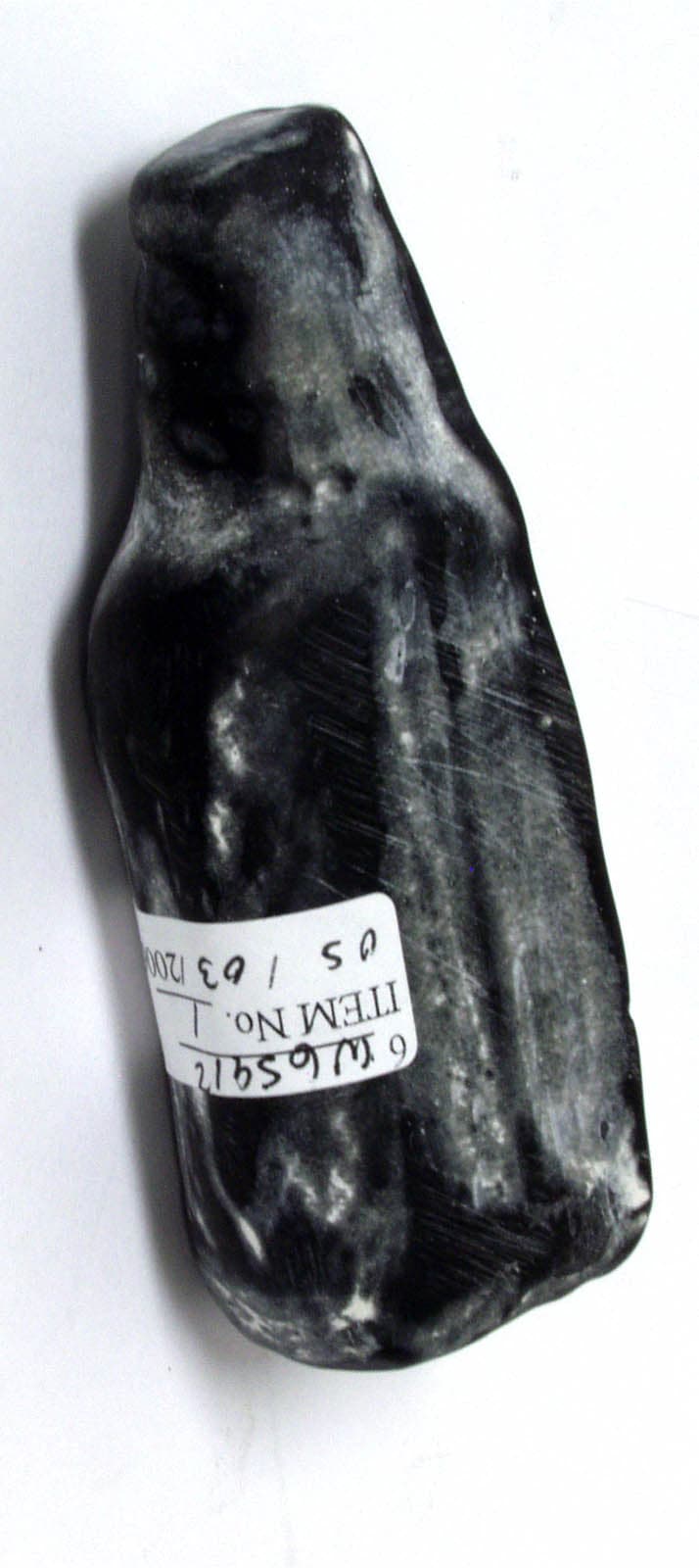
T9R-TAG3
May 24, 2006RFID Tag
Equipment Class
DTS - Digital Transmission System