TAZ2967MULTI-GLO WIRELESS CONTROLLER
Front Electronics (H.K.) Ltd.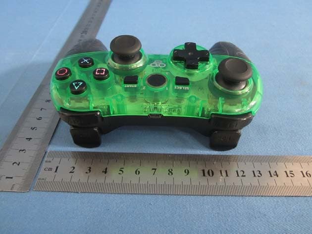
Click to zoom
Application Details
- Equipment Class
- DSS - Part 15 Spread Spectrum Transmitter
- Date of Grant
- Nov 28, 2013
- Application Purpose
- Original Equipment
- Date of Application
- Nov 28, 2013
- Equipment Note
- MULTI-GLO WIRELESS CONTROLLER
- Frequency Range
- 2409.00000000 - 2476.00000000
- Country
- Hong Kong
Documents & Files
Document Text
Text extracted from the exhibit documents filed with the FCC. Open a document above to read the original.
Users Manual
MULTI-GLO WIRELESS CONTROLLER User Manual Thank you for purchasing the Biogenik TM Wireless Controller for PS3. Please read this manual carefully. The contents of this package include: 1 x 2.4GHz Wireless Controller for PS3 1 x Controller Receiver Dongle 1 x Mini USB Charge Cable 1 x User Manual 1 x Warranty Card Product Features: 2.4Ghz Wireless Technology provides an operating distance up to 10 meters Bright LEDs light up translucent exterior shell Change colours on the fly ‐ 8 different LED color options Ergonomically designed for extended gaming sessions Textured rubber grips enhance comfort and grip Improved R2 & L2 trigger buttons give you an edge on the competition Built‐in dual rumble motors provide an immersive gaming experience Analog control sticks provide smooth, accurate targeting Built‐in 650mAh rechargeable Li‐ion battery Standby Mode preserves battery power when the controller is inactive Note: The Wireless Controller is only compatible with PS3 consoles. The Wireless Controller supports all games that feature the DualShock 3™ icon, however, the controller does not feature SIXAXIS. Product Diagram: (see below) LEFT 3D UP LEFT DOWN RIGHT SELECT START HOME RIGHT 3D USB (CHARGE) RESET BUTTON LIGHT BUTTON CONTROLLER RECEIVER DONGLE Synchronization Instructions: 1. Turn ON the PS3 console. 2. Plug the receiver dongle into an available USB port on the PS3 console. 3. Press the "HOME" button on the Wireless Controller. During synchronization, the LED on the receiver will flash quickly. If the channel LED and receiver LED both glow solid, the wireless connection was successful. If synchronization was unsuccessful, unplug the receiver dongle and repeat step 2. 4. After the first successful connection, the Wireless Controller and the receiver dongle will automatically connect when the controller is powered on or is awaken from sleep mode. Press the "HOME" button to re‐activate the connection. LED indicator and Player Channel Mapping: Player 1: LED 1 Player 2: LED 2 Player 3: LED 3 Player 4: LED 4 Player 5: LED 4 + LED 1 Player 6: LED 4 + LED 2 Player 7: LED 4 + LED 3 Note: The Player Channel LED is also used to indicate low battery power. It will flash quickly and the vibration will automatically be turned off to conserve battery power. Light Button Press the LED Light button on the back of the controller to change the color of the glowing effect. o The glowing effect will change in the following sequence: Red Green Blue Purple Baby Blue Yellow White Color Gradient OFF Red... Standby (Power Saving) Mode The Wireless Controller will automatically enter standby mode to conserve battery power when it hasn’t been used for a period of time. Press the “HOME” button to re‐activate the controller. The controller will automatically sync after returning to active mode. Troubleshooting The Wireless Controller does not work. If the Wireless Controller fails to operate, or operates incorrectly, follow the steps below before seeking assistance. Make sure the PS3 is turned ON and the receiver dongle is inserted properly. Make sure the Wireless Controller is properly synchronized with the receiver dongle. Make sure the Wireless Controller is within the operating distance. Make sure the battery of the Wireless Controller is fully charged. If after verifying the steps above, the Wireless Controller still does not work or does work not correctly, try the following: Turn OFF the power of the PS3 console. Wait a few seconds and then turn ON the PS3 console. Press the RESET button on the back of the Wireless Controller to reset the controller. Wait a few seconds and then re‐synchronize the Wireless Controller. FCC STATEMENTS This device complies with Part 15 of the FCC Rules. Operation is subject to the following two conditions: (1) This device may not cause harmful interference, and (2) this device must accept any interference received, including interference that may cause undesired operation. FCC ID: TAZ2967 MADE IN CHINA Warning: Modifications not approved by the party responsible for compliance could void user’s authority to operate the equipment. NOTE: This equipment has been tested and found to comply with the limits for Class B digital device, pursuant to part 15 of the FCC Rules. These limits are designed to provide reasonable protection against harmful interference in a residential installation. This equipment generates uses and can radiate radio frequency energy and, if not installed and used in accordance with the instructions, may cause harmful interference to radio or television reception, which can be determined by turning the equipment off and on, the user is encouraged to try to correct the interference by one or more of the following measures: • Reorient or relocate the receiving antenna. • Increase the separation between the equipment and the receiver. • Connect the equipment into an outlet on a circuit different from that to which the receiver is connected. • Consult the dealer or an experienced radio/TV technician for help. TouchSense® Technology Licensed from Immersion Corporation. Protected by one or more of the following patents: U.S. Patents: 5831408, 5844392, 5857986, 5907487, 5959613, 6020875, 6088017, 6104158, 6219032, 6246390, 6252583, 6271833, 6275213, 6278439, 6343349, 6400352, 6411276, 6424333, 6715045, 6801008, 7131073, 7199790, 7209117, 7299321, 7327348, 7345672, and 7502011.
ID Label/Location Info
Label location
RF Exposure Info
FCC ID:TAZ2967 The device has a standalone transmission. According to KDB 447498 section 4.3.1, the 1-g SAR test exclusion thresholds at test separation distances≤ 50 mm are determined by: [(max. power of channel, including tune-up tolerance, mW)/(min. test separation distance, mm)]·[√f(GHz)] ≤ 3.0 The maximum tune-up limit power is 0.255mW @ 2.409GHz For the head and body SAR, use 5mm as the conservative minimum test separation distance, [(max. power of channel, including tune-up tolerance, mW)/(min. test separation distance, mm)]·[√f(GHz)] =0.079≤ 3.0 So standalone SAR measurements are not required for both head and body.
Test Report
Global United Technology Services Co., Ltd. Report No.: GTSE13100166001 Authorized Signature: Robinson Lo Laboratory Manager This report details the results of the testing carried out on one sample. The results contained in this test report do not relate to other samples of the same product and does not permit the use of the GTS product certification mark. The manufacturer should ensure that all products in series production are in conformity with the product sample detailed in this report. This report may only be reproduced and distributed in full. If the product in this report is used in any configuration other than that detailed in the report, the manufacturer must ensure the new system complies with all relevant standards. Any mention of GTS International Electrical Approvals or testing done by GTS International Electrical Approvals in connection with, distribution or use of the product described in this report must be approved by GTS International Electrical Approvals in writing. This document cannot be reproduced except in full, without prior written approval of the Company. Any unauthorized alteration, forgery or falsification of the content or appearance of this document is unlawful and offenders may be prosecuted to the fullest extent of the law. Unless otherwise stated the results shown in this test report refer only to the sample(s) tested and such sample(s) are retained for 90 days only.” Page FCC REPORT Applicant: Front Electronics (H.K.) Limited Address of Applicant: Rm 2919, Asia Trade Centre, 79 Lei Muk Road, Kwai Chung Equipment Under Test (EUT) Product Name: MULTI-GLO WIRELESS CONTROLLER Model No.: FEL-2967 FCC ID: TAZ2967 Applicable standards: FCC CFR Title 47 Part 15 Subpart C Section 15.249:2012 Date of sample receipt: October 14, 2013 Date of Test: October 14-November 15, 2013 Date of report issued: November 15, 2013 Test Result : PASS * * In the configuration tested, the EUT complied with the standards specified above. Report No.: GTSE13100166001 Global United Technology Services Co., Ltd. Project No.: GTSE131001660RF 2nd Floor, Block No.2, Laodong Industrial Zone, Xixiang Road Baoan District, Shenzhen, China 518102 Telephone: +86 (0) 755 2779 8480 Fax: +86 (0) 755 2779 8960 Page 2 of 25 2 Version Version No. Date Description 00 November 15, 2013 Original Prepared By: Date: November 15, 2013 Project Engineer Check By: Date: November 15, 2013 Reviewer Report No.: GTSE13100166001 Global United Technology Services Co., Ltd. Project No.: GTSE131001660RF 2nd Floor, Block No.2, Laodong Industrial Zone, Xixiang Road Baoan District, Shenzhen, China 518102 Telephone: +86 (0) 755 2779 8480 Fax: +86 (0) 755 2779 8960 Page 3 of 25 3 Contents Page 1 COVER PAGE ............................................................................................................................................ 1 2 VERSION .................................................................................................................................................. 2 3 CONTENTS .............................................................................................................................................. 3 4 TEST SUMMARY ..................................................................................................................................... 4 5 GENERAL INFORMATION ...................................................................................................................... 5 5.1 CLIENT INFORMATION ......................................................................................................................... 5 5.2 GENERAL DESCRIPTION OF EUT ......................................................................................................... 5 5.3 TEST MODE ........................................................................................................................................ 7 5.4 DESCRIPTION OF SUPPORT UNITS ....................................................................................................... 7 5.5 TEST FACILITY .................................................................................................................................... 7 5.6 TEST LOCATION ................................................................................................................................. 7 5.7 OTHER INFORMATION REQUESTED BY THE CUSTOMER ......................................................................... 7 6 TEST INSTRUMENTS LIST ..................................................................................................................... 8 7 TEST RESULTS AND MEASUREMENT DATA ...................................................................................... 9 7.1 ANTENNA REQUIREMENT: .................................................................................................................... 9 7.2 RADIATED EMISSION METHOD ........................................................................................................... 10 7.2.1 Field Strength of The Fundamental Signal ................................................................................ 12 7.2.2 Spurious emissions .................................................................................................................... 13 7.2.3 Bandedge emissions.................................................................................................................. 17 7.3 20DB OCCUPY BANDWIDTH .............................................................................................................. 18 8 TEST SETUP PHOTO ............................................................................................................................ 20 9 EUT CONSTRUCTIONAL DETAILS ..................................................................................................... 21 Report No.: GTSE13100166001 Global United Technology Services Co., Ltd. Project No.: GTSE131001660RF 2nd Floor, Block No.2, Laodong …
Text truncated - open the document above for the full version.
Test Setup Photos
Radiated Emission
Contact Information
Applicant
CHIU MK(Director of Marketing)
Test Firm
Global United Technology Service Co., LtdRobinson Lo
Technical Specifications
| # | Rule Parts | Frequency Range | Power Output |
|---|---|---|---|
| 1 | 15C | 2.41 GHz - 2.48 GHz | 255.00 µW |
Other Applications from Front Electronics (H.K.) Ltd.
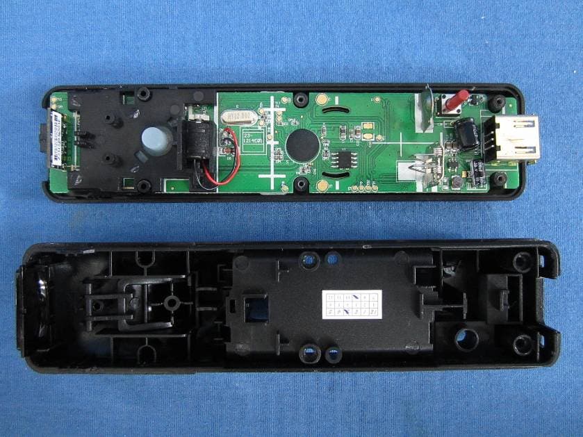
TAZWL015
Nov 01, 2012REMOTE FOR Wii
Equipment Class
DSS - Part 15 Spread Spectrum TransmitterTAZ2924A
Aug 30, 2012Tablet Case with Bluetooth� Keyboard
Equipment Class
DXX - Part 15 Low Power Communication Device Transmitter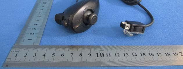
TAZASD798
Jun 06, 2012REMOTE with Motion Plus & PLAYCHUK for Wii
Equipment Class
DSS - Part 15 Spread Spectrum Transmitter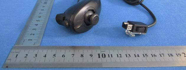
TAZASD837
Jun 06, 2012REMOTE & PLAYCHUK for Wii
Equipment Class
DSS - Part 15 Spread Spectrum Transmitter
TAZ2823
Aug 29, 2011PS3/PS2/PC 3in1 updatable steering wheel
Equipment Class
DXX - Part 15 Low Power Communication Device Transmitter