TAZGGE633060808Wireless 2 Control Pad
Front Electronics (H.K.) Ltd.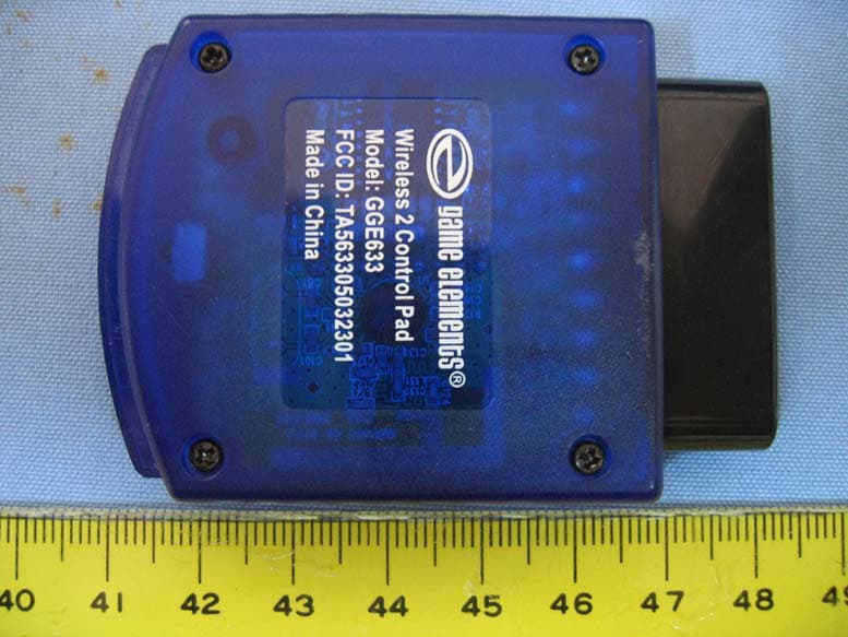
Click to zoom
Application Details
- Equipment Class
- DSS - Part 15 Spread Spectrum Transmitter
- Date of Grant
- Sep 03, 2006
- Application Purpose
- Original Equipment
- Date of Application
- Sep 03, 2006
- Equipment Note
- Wireless 2 Control Pad
- Frequency Range
- 2410.00000000 - 2470.00000000
- Country
- Hong Kong
Documents & Files
Document Text
Text extracted from the exhibit documents filed with the FCC. Open a document above to read the original.
Users Manual
Wireless 2 Control Pad for PS2 TM DVD Remote Model #GGE633 PS2 Wireless 2 Control Pad-DVD Remote Model #GGE633 IMPORTANT: Before using this product please read the PlayStation 2™ video game system instruction manual for safety, health and other information. INTRODUCTION Congratulations on purchasing the Wireless 2™ Control Pad-DVD remote for use with the PS2 game console. You now can experience total control over your console. The Wireless 2 is equipped with integrated DVD functions hid- den under the retractable panel so no other remote is needed when you want to play DVD movies. Please familiarize yourself on the func- tionality by reviewing these operational instructions. Technology Features A) 2.4 GHz Wireless technology with 27 Function IR Integrated buttons for DVD playback B) Built in auto switching when using two or more wireless controllers together C) Up to 50 Foot operational range Functional Features A Two (2) fully pressure sensitive analog con- trol sticks-Left / Right B) Four (4) fire buttons - C) Four shoulder fire buttons (R1,R2,L1,L2) D) Start / Play / Pause button. E) Select / Display button F) Illuminated Analog Button G) 8-way directional control pad H) On / Off switch I) Under panel DVD functions COMATIBILITY The software used will dictate the functionality of the controller buttons. See the controller set up in the software instructions for more detailed information. Some of the under panel DVD functions are only compatible for use on the PS2 model numbers SCPH-50001, and SCPH-70012. INSTALLATION AND SET UP 1) Remove the battery cover on the back of the Wireless 2 Controller and install 3 AA batteries (Not Included) into the compart- ment. Make sure to install the batteries with the polarity direction in the proper manner (+ -). 2) With the game console off connect the controller receiver into player port one or two. 3) Turn on the game console and switch on the Wireless 2 game pad. A Red LED will illuminate on the receiver signifying the receiver is powered. The Green LED on the receiver will illuminate and notes when the controller and receiver are synchronized. The receiver will flash if scanning for the controller. OPERATIONAL NOTE: Use only new batteries together. Do not install new and old batteries together as functionality problems may occur. Remove batteries if pad is going to be left for a long period of time or voltage is low. Wireless 2 is not Dual Shock™ vibration compatible. ANALOG BUTTON Use to switch between digital and analog. In the digital mode the controller will act like the original Sony ® controller for PS2. The analog sticks will operate the same as the directional pad. The L3 & R3 buttons are not active. In the analog mode you will have more accurate con- trol over your movements. The LED light on the Analog button will be illuminated when Analog function is on. Note:Always refer to the software you are using for the suggested modes of play. SLEEP AND WAKE UP MODE In order to preserve battery life the Wireless 2 pad has a sleep and wake up mode built in. The pad will enter into Sleep mode after 3 minutes of inactivity. Please note the following points regarding the feature: •Wireless 2 pad will enter sleep mode after 2 minutes of operation •To wake up Wireless 2 pad press any but- ton such as R1, R2, X. Pad will resume operation after 3 seconds DVD FUNCTIONS AND OPERATION For use on PS2 Versions-SCPH-50001 and 70012 You can access all the basic DVD player func- tions found in the PS2 by using the Wireless 2. For detailed explanation of the each function see the included chart. The PS2 SCPH-50001 and 70002 are the newest PS2 consoles with progressive scan and other new features. These consoles have a built in integrated IR receiver and therefore can be controlled right from the Wireless 2 game pad when pointed at the IR receiver on the console. If operating with the PS2 version SCPH-50001 you can have the DVD tray EJECT/CLOSE right from the Wireless 2. NOTE: Some functions of the DVD playback will operate from some of the external buttons found and labeled on the controller such as the fire and shoulder buttons. Setting up the remote and starting DVD Playback 1) Press main power switch on the PS2 con- sole rear or front depending on which ver- sion you have to turn the console on. 2) Press the reset button of the Wireless 2 control pad. 3) Press the open/close button on the Wireless 2 control pad (PS2 model SCPH- 50012 only) or manually on the console. 4) Place the DVD in the PS2 console tray 5) Press the open/close button and the tray will close (SCPH050012 only). DVD con- tent on the screen will appear. Ending DVD Playback 1) Press the open/close button on the con- sole or Wireless 2 game pad. 2) Remove the disc from the PS2 tray. 3) Press the open/close button on the con- sole or Wireless 2. 4) Press and hold down the reset button. The PS2 “On” LED turns red and enters stand by mode. Note: Consult the chart for all other button functions. Installation and operation when using PS2 Versions SCPH-30001 to SCPH-39001 (Dongle Required) In order to use the Wireless 2 Game Pad with the older PS2 consoles, “you must keep the included receiver dongle connected”. Use the below installation and operation procedure: Setting up the Wireless 2 and starting DVD Playback 1) Make sure the receiver dongle is connected into player port 1 on the PS2 console. 2) Manually press main power switch on the PS2 console rear to turn the console on. 3) Manually press the reset button on the PS2. 4) Manually press the open /close button on the PS2 console front. 5) Place the DVD in the PS2 tray. 6) Manually press the open/close button on the PS2 console and the tray will close. DVD content will appear on the screen. Note:Consult the chart for DVD button func- tions. No memory card or software is required to operate the Wireless 2 Controller. Some functions noted in the included chart will not be compatible on the SCPH-30001 to SCPH- 39001 PS2 consoles and will need to…
Text truncated - open the document above for the full version.
Block Diagram
1 2 34 ABCD 4 3 2 1 D CBA Part No. Prepared By Date Approved By Qi Yong File No. WF-PIE-042/A FRONT ELECTRONIC CO., LTD. TITLE Rev:Model No. 2006-06-09 FEL-2088 A02 DI DO 8V GND 3.5V CS CLK NC ACK PS2 Console Interface ACK CLK CSI 3.5V GND 8V DO] DIDI DO GND 3.5V CSO CLK ACK IR&RF Auto Change Circuit ACK DO GND 3.5V CS CLK ACK I/O 3.5V GND RF MCU VCC I/O I/O GND RF MCU GND Vbat I/O IR MCU I/OGND IR Keys I/O GND RF Keys&Analogue 3D Stick GNDI/O3.5V RF Module VCC GND I/O RF Module Vbat VCC GND POWER Receiver Transmitter Block Diagram For PS2 2.4G RF Gamepad With IR DVD Remote Function
External Photos
Spectrum Research & Testing Lab., Inc. No. 101-10, Ling 8, Shan-Tong Li, Chung-Li City, Taoyuan, Taiwan, R.O.C. Photo Page: 1 of 10 - PHOTOS OF EUT-TX Spectrum Research & Testing Lab., Inc. No. 101-10, Ling 8, Shan-Tong Li, Chung-Li City, Taoyuan, Taiwan, R.O.C. Photo Page: 2 of 10 - PHOTOS OF EUT-TX Spectrum Research & Testing Lab., Inc. No. 101-10, Ling 8, Shan-Tong Li, Chung-Li City, Taoyuan, Taiwan, R.O.C. Photo Page: 3 of 10 - PHOTOS OF EUT-TX CASE Spectrum Research & Testing Lab., Inc. No. 101-10, Ling 8, Shan-Tong Li, Chung-Li City, Taoyuan, Taiwan, R.O.C. Photo Page: 4 of 10 - PHOTOS OF EUT-TX ACCESSORY Spectrum Research & Testing Lab., Inc. No. 101-10, Ling 8, Shan-Tong Li, Chung-Li City, Taoyuan, Taiwan, R.O.C. Photo Page: 7 of 10 - PHOTOS OF EUT-RX Spectrum Research & Testing Lab., Inc. No. 101-10, Ling 8, Shan-Tong Li, Chung-Li City, Taoyuan, Taiwan, R.O.C. Photo Page: 8 of 10 - PHOTOS OF EUT-RX CASE
ID Label/Location Info
Spectrum Research & Testing Lab., Inc. No. 101-10, Ling 8, Shan-Tong Li, Chung-Li City, Taoyuan, Taiwan, R.O.C. Sample of FCC ID Label The device is large enough for it to be placed warning statement on the device as follow: FCC ID: TAZGGE633060808
Internal Photos
Spectrum Research & Testing Lab., Inc. No. 101-10, Ling 8, Shan-Tong Li, Chung-Li City, Taoyuan, Taiwan, R.O.C. Photo Page: 5 of 10 - PHOTOS OF EUT-TX PCB Spectrum Research & Testing Lab., Inc. No. 101-10, Ling 8, Shan-Tong Li, Chung-Li City, Taoyuan, Taiwan, R.O.C. Photo Page: 6 of 10 - PHOTOS OF EUT-TX PCB - PHOTOS OF EUT-TX TOP IN Spectrum Research & Testing Lab., Inc. No. 101-10, Ling 8, Shan-Tong Li, Chung-Li City, Taoyuan, Taiwan, R.O.C. Photo Page: 9 of 10 - PHOTOS OF EUT-RX PCB Spectrum Research & Testing Lab., Inc. No. 101-10, Ling 8, Shan-Tong Li, Chung-Li City, Taoyuan, Taiwan, R.O.C. Photo Page: 10 of 10 - PHOTOS OF EUT-RX TOP IN
Operational Description
Spectrum Research & Testing Lab., Inc. No. 101-10, Ling 8, Shan-Tong Li, Chung-Li City, Taoyuan, Taiwan, R.O.C. Operational Description of equipment Wireless 2 Control Pad FCCID: TAZGGE633060808 (1) Puts the dongle part into the game system’s pad slot, then turns on the game system. (2) Press the connect button of the dongle. At the same time, the LED is going to flash. (3) Press the connecting button of game pad, it will flash too. When the LED sustain light at both game pad and dongle. The game pad can be used to control the game system. PRODUCT Wireless 2 Control Pad MODEL NO. GGE 633 POWER SUPPLY DC 4.5 V, 0.1A FREQUENCY BAND 2.410~2.470GHz CARRIER FREQUENCY 2.410GHz NUMBER OF CHANNEL 74 CHANNEL SPACING 810.9KHz RATED RF OUTPUT POWER 0dBm (1mW) I.F. & L.O. I.F.:374MHz,L.O.:2410-2470 MHz MODULATION TYPE MSK BIT RATE OF TRANSMISSION 250Kbps DUTY CYCLE Max 1600 hops/sec ANTENNA TYPE PCB Antenna ANTENNA GAIN Max 2 dBi OPERATING TEMPERATURE -40~85°C CHANNEL BANDWIDTH 1MHz
Schematics
1 2 3 4 5 6 ABCD 6 5 4 3 2 1 D CBA S32 OPEN/CLOSE Q5 D6 R17470 Vbat OUT S49RESET S37 SHUFFLE S31 S262 S1 3 S8BANGLE S48PROGRAM S25 4 S2 5 S27 6 S18REPEAT S2 7 S28 8 S15 9 S22SLOW<- S5BSLOW-> S39CLEAR S40 0 S19TIME S17A-B S20TOP MENU S45MENU S13RETURN S38ENTER K10 K11 K12 K13 K14 K15 K16 K17 KO0KO1KO2KO3KO4 Y2480K C11200P C12 200P R20470R C13 104 OUT KO0KO1KO2KO3KO4KO5KO6 K10K11K12K13 K14 K15K16K17 VCC OSCO 1 OSCI 2 VDD 3 GND 4 TX 5 DLED 6 BLED 7 KI0 8 KI1 9 KI2 10 KI3 11 KI4 12 KI5 13 KI6 14 KI7 15 KO0 16 KO1 17 KO2 18 KO3 19 KO4 20 KO5 21 KO6 22 U4MAS232-01H VCC GND 1 VIN 2 VOUT 3 U1HT7530 C2100uF Y1 12M C9 22p C10 22p K11 R2 K7 Circle K8 Square K9 Cross K10 Triangle S1Select S8 Mode S2 Start S4 R3 S3L3 R1 15K R2 56K R439KR3100K R510K Low Voltage Detect AD_COM LVD_IN LVD_IN P1 Battery C1104p Vbat Vbat C4104p C347uF C5104p VCC VCC N ote: 1.The key's carbon film of resistor must be print for connection, The size is 10K±20%; 2.The following keys are wake-up keys: Select, Start,L3,R3,Mode K12 R1 R9 1K VCC Regulate the resistance of these resistor can change the warning low voltage. R610K VCC Q1S9012 Q2S8050 SW1 Power switch R8 1K VCC EE_CS A -+ Motor1 Left Motor Q3 S8050 Vbat R1133ohm* R132.7K D34148 C8 104p LEFT_MOTOR RIGHT_MOTOR A -+ Motor2Right Motor Q4 S8050 R1233ohm* R142.7K D44148 C7104p Vbat C6104p VCC CS 1 CLK 2 DI 3 DO 4 VSS 5 ORG 6 NC 7 VCC 8 U293C46-A VCC Select:(Optional) If use EEPROM(93c46),The forcibly connect keys are SELECT+L3 S7 Macro S6 Clear/Slow S5 Turbo R7 1K VCC VR1LX VR2 LY VR3 RX VR4 RY Low voltage warning of this circuit is 2.3V,warn by high level. VSS 41 /INT 42 DATA/RFC17 43 CLK/RFC18 44 IOE0 1 IOE1 2 IOE2/SDI 3 IOE3/SDO 4 IOE4/SCK 5 IOE5/SSB 6 IOA0/PWM0 7 IOA1/CX 8 IOA2/RFC0 9 IOA3/RFC1 10 IOA4/RFC2 11 IOA5/RFC3 12 IOA6/RFC4 13 IOA7/RFC5 14 IOD0/RFC6 15 IOD1/RFC7 16 IOD2 18 IOD3 19 IOD4 20 IOD5 21 IOD6 22 IOD7 23 IOB0/T23CKI 24 IOB1/RFC8 25 IOB2/RFC9 26 IOB3/RFC10 27 IOB4/RFC11 28 IOB5/RFC12 29 IOB6/RFC13 30 IOB7/RFC14 31 IOC2/RFC15 32 IOC1/RFC16 33 IOC0/PWM1 34 VDD 38 OSCI 39 OSCO 40 RSTB 17 IOC3 35 IOE6 36 IOE7/CKOUT 37 R10 AT8P51 AD_COM K4 Down K5 Left K6Right K2 L2 K3 Up K1 L1 VCC EE_CS EE_CS IOD2 IOD3 IOD4 IOD5 IOD6 IOD2IOD3IOD4 RIGHT_MOTOR LEFT_MOTOR D5 Turbo/Macro LED D2 Mode/Link/Low power D1 Mode2/Low power CX1822* Mylar VCC R15 10ohm AD_IN GDO2 4 SO/GDO1 5 SCLK 6 SI 7 VCC 8 GDO0 2 CS 1 GND 3 2mm GND 9 CON1CC2500_PORT2 R16 10K R17 10K VCC FOR Special LED FOR Standard AD_COM Y X IR Part No. Prepared By Date Approved By Qi Yong File No. WF-PIE-042/A FRONT ELECTRONIC CO., LTD. TITLE Rev: A02Model No.FEL-2088 2006-06-09 20880104.SCH Circuit Diagram For PS2 2.4G RF Gamepad With IR DVD Remote Function(Transmitter) 1 2 3 4 5 6 78 ABCD 8 7 6 5 4 3 2 1 D CBA Y112M C522P C4 22P LED1Link_LED C2104 R21K C122uF VCC VCC VCC DI 1 DO 2 7.5V 3 GND 4 3.5V 5 /CS 6 CLK 7 GUN 8 /ACK 9 CN3 LED3Power_LED R101K VCC OP_Turbo S3 OP_Mode OP_MODE Open - 2 modes(STD, Analog) Short - 3 modes(STD, Analog, Negcon) OP_TURBO Open - Turbo ON/Clear OFF Short - Turbo ON/Turbo OFF OP_3DMAP Open - No 3D map Short - 3D map to key in STD mode FC Force Connect OP_3DMAP R64.7K FC VSS 41 /INT 42 DATA(P75,7) 43 CLK(P74,6) 44 P90 1 P91 2 P92(SDI) 3 P93(SDO) 4 P94(SCK) 5 P95(/SS) 6 P50 7 P51 8 P52 9 P53 10 P54 11 P55 12 P56 13 P57 14 P80 15 P81 16 P82 18 P83 19 P84 20 P85 21 P86 22 P87 23 P60 24 P61 25 P62 26 P63 27 P64 28 P65 29 P66 30 P67 31 P72 32 P71 33 P70 34 VDD 38 R-OSCI 39 OSCO 40 NC 17 NC 35 NC 36 NC 37 U1 EMC78P451Q VCC CS-O DI DO ACK CLK 8V 123456789 J1IN CS-IDIDOACKCLK8VGND To PS2 Console VCC C10 4.7U/6.3V 1 2 3 U1 RECEIVE RE 8V PIC 1010 C8 104 VCC R9 100 Z1 5.1V C7 4.7U/6.3V C6 104 5.1V CS-I DIDOCSICLKACKCSO CS-ODIDOACKCLK S1 VCC JAPANUSA R12 470 LED4 VCC VCC Y2 20MHZ C9 20P C1120P S2 AUTO MANUAL RE RECEIVE LED LED VCC RA2 1 RA3 2 TOCLK 3 MCLR 4 GND 5 RB0 6 RB1 7 RB2 8 RB3 9 RB4 10 RB5 11 RB6 12 RB7 13 VDD 14 OSCO 15 OSCI 16 RA0 17 RA1 18 ____ U3TM58P10 R81.5KR115.6K R131.5K Q18550 R16 0 CS-I CS-O RE SEL R1 22 R5 1K R3 1K R15 22 R14 1K R71K VCC VCC C3104 VCC CS 1 SK 2 DI 3 DO 4 GND 5 ORG 6 NC 7 VCC 8 U2 93C46 VCC GDO2 4 SO/GDO1 5 SCLK 6 SI 7 VCC 8 GDO0 2 CS 1 GND 3 2mm GND 9 CON1CC2500_PORT2 LED2Mode_LED R41K VCC IR Part No. Prepared By Date Approved By Qi Yong File No. WF-PIE-042/A FRONT ELECTRONIC CO., LTD. TITLE Rev: A02Model No.FEL-2088 2006-06-09 20880404.SCH Circuit Diagram For PS2 2.4G RF Gamepad With IR DVD Remote Function(Receiver)
Test Report
Spectrum Research & Testing Lab., Inc. No. 101-10, Ling 8, Shan-Tong Li, Chung-Li City, Taoyuan, Taiwan TEST REPORT Reference No.: A06071801 Report No.: FCCA06071801 FCCID: TAZGGE633060808 Page:2 of 53 Date: Aug. 09, 2006 TABLE OF CONTENTS 1. DOCUMENT POLICY AND TEST STATEMENT ..................................................... 4 1.1 DOCUMENT POLICY ........................................................................................... 4 1.2 TEST STATEMENT............................................................................................... 4 1.3 EUT MODIFICATION ............................................................................................. 4 2. DESCRIPTION OF EUT AND TEST MODE ........................................................... 5 2.1 GENERAL DESCRIPTION OF EUT ..................................................................... 5 2.2 DESCRIPTION OF SUPPORT UNIT .................................................................... 6 2.3 DESCRIPTION OF TEST MODE .......................................................................... 6 3. DESCRIPTION OF APPLIED STANDARDS .......................................................... 7 4. TECHNICAL CHARACTERISTICS TEST .............................................................. 8 4.1 CHANNEL SEPARATION TEST........................................................................... 8 4.1.1 LIMIT.................................................................................................................. 8 4.1.2 TEST EQUIPMENT............................................................................................ 8 4.1.3 TEST SET-UP .................................................................................................... 8 4.1.4 TEST PROCEDURE .......................................................................................... 8 4.1.5 EUT OPERATING CONDITION ......................................................................... 9 4.1.6 TEST RESULT ................................................................................................... 9 4.2 20DB BANDWIDTH ............................................................................................ 13 4.2.1 LIMIT................................................................................................................ 13 4.2.2 TEST EQUIPMENT.......................................................................................... 13 4.2.3 TEST SET-UP .................................................................................................. 13 4.2.4 TEST PROCEDURE ........................................................................................ 13 4.2.5 EUT OPERATING CONDITION ....................................................................... 13 4.2.6 TEST RESULT ................................................................................................. 14 4.3 QUANTITY OF HOPPING CHANNEL TEST...................................................... 17 4.3.1 LIMIT................................................................................................................ 17 4.3.2 TEST EQUIPMENT.......................................................................................... 17 4.3.3 TEST SET-UP .................................................................................................. 17 4.3.4 TEST PROCEDURE ........................................................................................ 17 4.3.5 EUT OPERATING CONDITION ....................................................................... 17 4.3.6 TEST RESULT ................................................................................................. 18 4.4 TIME OF OCCUPANCY (DWELL TIME) ............................................................ 19 4.4.1 LIMIT................................................................................................................ 19 4.4.2 TEST EQUIPMENT.......................................................................................... 19 4.4.3 TEST SET-UP .................................................................................................. 19 4.4.4 TEST PROCEDURE ........................................................................................ 19 4.4.5 EUT OPERATING CONDITION ....................................................................... 19 4.4.6 TEST RESULT ................................................................................................. 20 4.5 PEAK POWER TEST.......................................................................................... 23 4.5.1 LIMIT................................................................................................................ 23 4.5.2 TEST EQUIPMENT.......................................................................................... 23 4.5.3 TEST SET-UP .................................................................................................. 24 4.5.4 TEST PROCEDURE ........................................................................................ 24 Spectrum Research & Testing Lab., Inc. No. 101-10, Ling 8, Shan-Tong Li, Chung-Li City, Taoyuan, Taiwan TEST REPORT Reference No.: A06071801 Report No.: FCCA06071801 FCCID: TAZGGE633060808 Page:3 of 53 Date: Aug. 09, 2006 4.5.5 EUT OPERATING CONDITION ....................................................................... 24 4.5.6 TEST RESULT ................................................................................................. 24 4.6 BAND EDGE TEST............................................................................................. 28 4.6.1 LIMIT................................................................................................................ 28 4.6.2 TEST EQUIPMENT.......................................................................................... 29 4.6.3 TEST SET-UP ...............................................................................................…
Text truncated - open the document above for the full version.
Test Setup Photos
Spectrum Research & Testing Lab., Inc. No. 101-10, Ling 8, Shan-Tong Li, Chung-Li City, Taoyuan, Taiwan TEST REPORT Reference No.: A06071801 Report No.: FCCA06071801 FCCID: I4L-MS6868I Page:50 of 53 Date: Aug. 09, 2006 6. PHOTOS OF TESTING - Radiated test (TX) Spectrum Research & Testing Lab., Inc. No. 101-10, Ling 8, Shan-Tong Li, Chung-Li City, Taoyuan, Taiwan TEST REPORT Reference No.: A06071801 Report No.: FCCA06071801 FCCID: I4L-MS6868I Page:51 of 53 Date: Aug. 09, 2006 - Radiated test (LINK) Spectrum Research & Testing Lab., Inc. No. 101-10, Ling 8, Shan-Tong Li, Chung-Li City, Taoyuan, Taiwan TEST REPORT Reference No.: A06071801 Report No.: FCCA06071801 FCCID: I4L-MS6868I Page:52 of 53 Date: Aug. 09, 2006 - Conducted test (TX)
Contact Information
Applicant
CHIU MK(Director of Marketing)
Test Firm
Spectrum Research & Testing Laboratory, Inc.Cheng Ho
Technical Specifications
| # | Rule Parts | Frequency Range | Power Output |
|---|---|---|---|
| 1 | 15C | 2.41 GHz - 2.47 GHz | 1.00 mW |
Other Applications from Front Electronics (H.K.) Ltd.
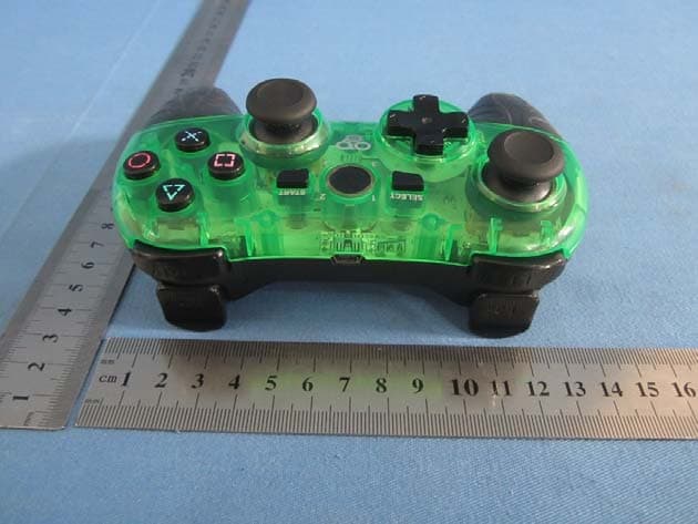
TAZ2967
Nov 28, 2013MULTI-GLO WIRELESS CONTROLLER
Equipment Class
DSS - Part 15 Spread Spectrum Transmitter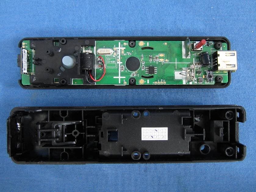
TAZWL015
Nov 01, 2012REMOTE FOR Wii
Equipment Class
DSS - Part 15 Spread Spectrum TransmitterTAZ2924A
Aug 30, 2012Tablet Case with Bluetooth� Keyboard
Equipment Class
DXX - Part 15 Low Power Communication Device Transmitter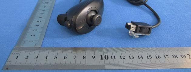
TAZASD798
Jun 06, 2012REMOTE with Motion Plus & PLAYCHUK for Wii
Equipment Class
DSS - Part 15 Spread Spectrum Transmitter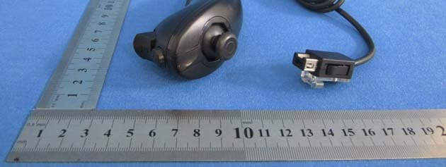
TAZASD837
Jun 06, 2012REMOTE & PLAYCHUK for Wii
Equipment Class
DSS - Part 15 Spread Spectrum Transmitter