TB7DXTOYS5594949MHz Radio Transmitter
Shantou Chenghai Dongxin Plastic Toys Co., Ltd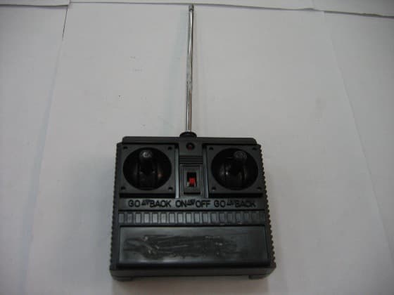
Click to zoom
Application Details
- Equipment Class
- DXX - Part 15 Low Power Communication Device Transmitter
- Date of Grant
- Jul 17, 2005
- Application Purpose
- Original Equipment
- Date of Application
- Jul 17, 2005
- Equipment Note
- 49MHz Radio Transmitter
- Frequency Range
- 49.86000000 - 49.86000000
- Country
- China
Documents & Files
Document Text
Text extracted from the exhibit documents filed with the FCC. Open a document above to read the original.
Users Manual
Usuer manual remote-controller’s battery installation 1realease the cover of battery box 2Install a 9V 6F22ND battery into battery compartment according to the right poles 3Close the cover of the battery box car battery installation 1 Turn the lock device of the battery compartment to a right position; 2 Remove the cover of the battery compartment ; 2Install six AA batteries into battery compartment according to the right poles 3close the cover of the battery compartment; 5lock the cover again use instruction (1)Turn the power switch of controller and car-body to “ON” position; (2)The light on controller will be on. When the light is turning dimmer and dimmer, the batteries are to be replaced; (3)Operate the handle of the controller, the car can move forward/backward, roll left/right or stop. The body-light can also light. (4)After play, turn the power switches to “OFF” position. NOTE: THE MANUFACTURER IS NOT RESPONSIBLE FOR ANY RADIO OR TV INTERFERENCE CAUSED BY UNAUTHORIZED MODIFICATIONS TO THIS EQUIPMENT. SUCH MODIFICATIONS COULD VOID THE USER AUTHORITY TO OPERATE THE EQUIPMENT.
Block Diagram
Transmitter: When press the control key forward/backward/right-ward/left-ward, the instruction were input to the coding circuit; The coded signal is amplified together with high frequency vibration signal; After LC filter, the signal is transmit by the antenna. Receiver: High frequency signal passes the antenna and enter the decoding circuit; After decoding, output action signal(+5V); The action signal voltage is amplified and drive the motors running individually. Instruction Coding circuit Quatz vibrating circuit antenna LC filter Amplifying circuit antenna High frequency signal Amplifying circuit Decoding circuit Turning drive circuit OTL Amplifying circuit Forward/backward drive circuit
ID Label/Location Info
FCC ID Label Sample FCC ID: TB7DXTOYS55949 This device complies with Part 15 of the FCC Rules. Operation is subject to the following two conditions: (1) this device may not cause harmful interference, and (2) this device must accept any interference received, including interference that may cause undesired operation.
Operational Description
Operation Description Transmitter: When press the control key forward/backward/right-ward/left-ward, the instruction were input to the coding circuit; The coded signal is amplified together with high frequency vibration signal; After LC filter, the signal istransmit by the antenna. Receiver: High frequency signal passes the antenna and enter the decoding circuit; After decoding, output action signal(+5V); The action signal voltage is amplified and drive the motors running individually.
Operational Description
CIRCUIT DESCRIPTION TRANSMIT Part: TX-2: IC1 is a 4 functional remote encoder IC. it’s work with transistor Q1, Q2 and other components combined as RF transmitter circuit. The IC Pin 1, 14, 4 and 6 control left, right, backward, forward and encoding signal output respectively. Data output from Pin 8 and modulate with 49MHz oscillator that achieved by Q2, Y1, R2, R3, L3and C3. RF power amplifier Q1, L1,L2, C1, C2 are used to enlarge the transmission range. ANTENNA GROUND CIRCUITRY This unit makes use of an external 20-inch rod antenna, the antenna is inductively coupled, the unit relies on the Ground trace of the circuit board. A 9V alkaline battery supplies energy.
Test Report
Report No.: GLEMO050501447RFF(I) Page : 1 of 13 FCC ID : TB7DXTOYS55949 Authorized Signature: Kent Hsu Laboratory Manager This report refers to the General Conditions for Inspection and Testing Services, printed overleaf This report details the results of the testing carried out on one sample. The results contained in this test report do not relate to other samples of the same product. The manufacturer should ensure that all products in series production are in conformity with the product sample detailed in this report. This report may only be reproduced and distributed in full. If the product in this report is used in any configuration other than that detailed in the report, the manufacturer must ensure the new system complies with all relevant standards. Any mention of SGS International Electrical Approvals or testing done by SGS International Electrical Approvals in connection with, distribution or use of the product described in this report must be approved by SGS International Electrical Approvals in writing. The report must not be used by the client to claim product certification, approval, or endorsement by NVLAP, NIST, or any agency of the federal government. All test results in this report can be traceable to National or International Standards. Member of the SGS Group (SGS SA) SGS-CSTC Standards Technical Services Co., Ltd. 1/F., Building No. 1 Building, Agriculture Machinery Materials Co. Wushan Road, Shipai, Tianhe District,Guangzhou, China Telephone: +86 (0) 20 3848 1001 Fax: +86 (0) 20 3848 1006 Email: [email protected] FEDERAL COMMUNICATIONS COMMISSION Registration number: 282399 TEST REPORT Application No. : GLEMO050501447RF Applicant : SHANTOU CHENGHAI DONGXIN PLASTIC TOYS CO., LTD. FCC ID : TB7DXTOYS55949 Fundamental Frequency : 49.860MHz Equipment under Test (EUT): Name : Toy – R/C Spinning Car (49MHz) Model : # 1602345 Customer PO No.: DSM5509 Standards : FCC PART 15, SUBPART C : 2004 Section 15.235 Date of Receipt : 26 May 2005 Date of Test : 27 May to 20 June 2005 Date of Issue : 21 June 2005 Test Result : PASS * * In the configuration tested, the EUT complied with the standards specified above. TB7 FCC ID: TB7DXTOYS55949 Report No.: GLEMO050501447RFF(I) Page : 2 of 13 SGS-CSTC Standards Technical Services Co., Ltd. 2 Test Summary Test Test Requirement Stanadard Paragraph Result Radiated Emission (30MHz to 1000MHz) FCC PART 15 :2004 Section 15.235 PASS ① Occupied Bandwidth FCC PART 15 :2004 Section 15.235 PASS Remark: ①The EUT passed Radiated Emission test after the modification as shown as the below: 1. Added two capacitor as the below: (C102: 82PF, C101: 5PF) . Please refer the section 6 of this report and circuit diagram for the detail. TB7 FCC ID: TB7DXTOYS55949 Report No.: GLEMO050501447RFF(I) Page : 3 of 13 SGS-CSTC Standards Technical Services Co., Ltd. 3 Contents Page 1 COVER PAGE ...........................................................................................................................................1 2 TEST SUMMARY....................................................................................................................................................2 3 CONTENTS..............................................................................................................................................................3 4 GENERAL INFORMATION...................................................................................................................................4 4.1 CLIENT INFORMATION....................................................................................................................................... 4 4.2 DETAILS OF E.U.T............................................................................................................................................ 4 4.3 DESCRIPTION OF SUPPORT UNITS................................................................................................................... 4 4.4 TEST LOCATION................................................................................................................................................ 4 4.5 OTHER INFORMATION REQUESTED BY THE CUSTOMER.................................................................................. 4 4.6 TEST FACILITY................................................................................................................................................... 5 5 TEST RESULTS......................................................................................................................................................6 5.1 TEST INSTRUMENTS.......................................................................................................................................... 6 5.2 E.U.T. OPERATION........................................................................................................................................... 6 5.3 TEST PROCEDURE & MEASUREMENT DATA..................................................................................................... 6 5.3.1 Radiated Emissions...................................................................................................................................6 5.3.2 Occupied Bandwidth.................................................................................................................................9 5.3.3 Photographs - Radiated Emission Test Setup in Chamber...............................................................10 6 PHOTOGRAPHS - EUT CONSTRUCTIONAL DETAILS..........................................................................11-13 TB7 FCC ID: TB7DXTOYS55949 Report No.: GLEMO050501447RFF(I) Page : 4 of 13 SGS-CSTC Standards Technical Services Co., Ltd. 4 General Information 4.1 Client Information Applicant: SHANTOU CHENGHAI DONGXIN PLASTIC TOYS CO., LTD. Address of Applicant: Crossing, Fengxin san Rd. Laiwu Rd. Changhai District, Shantou Guangdong China. 4.2 Details of E.U.T. Product Name: Toy –…
Text truncated - open the document above for the full version.
Contact Information
Applicant
Xie Licai(Vice General Manager)
Test Firm
SGS-CSTC Standards Technical Services Co., LtdJerry Chan
Technical Specifications
| # | Rule Parts | Frequency Range | Power Output |
|---|---|---|---|
| 1 | 15C | 49.86 MHz - 49.86 MHz | - |
Other Applications from Shantou Chenghai Dongxin Plastic Toys Co., Ltd
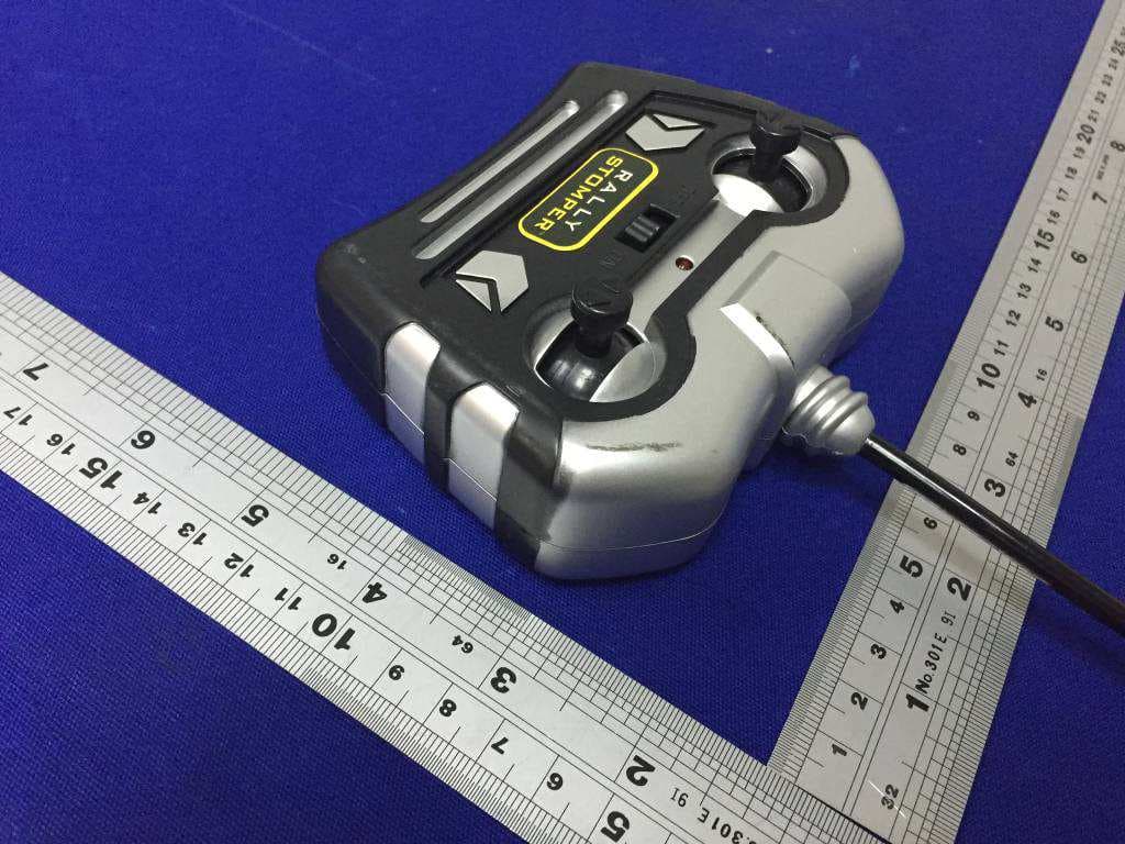
TB7DXTOYS3209049B
Sep 28, 2015TOY RC TRUCK
Equipment Class
DXX - Part 15 Low Power Communication Device Transmitter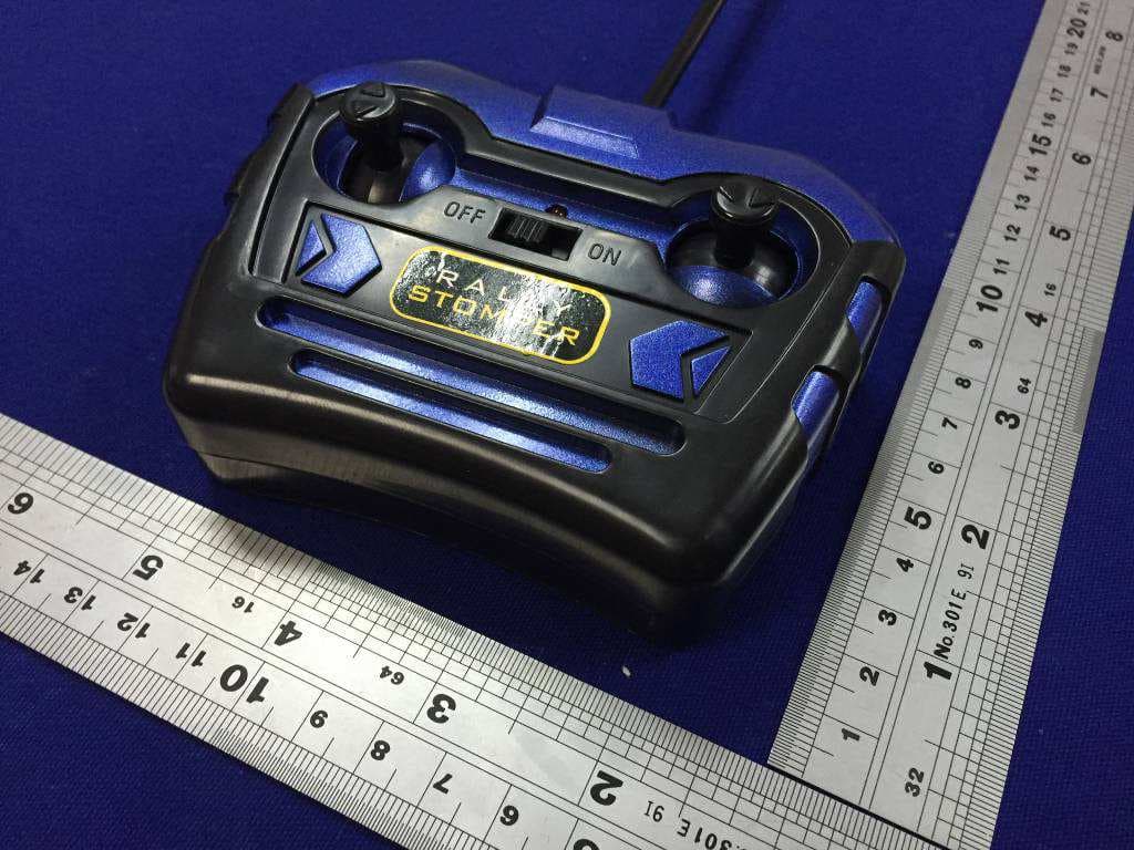
TB7DXTOYS3209027B
Sep 28, 2015TOY RC TRUCK
Equipment Class
DXX - Part 15 Low Power Communication Device Transmitter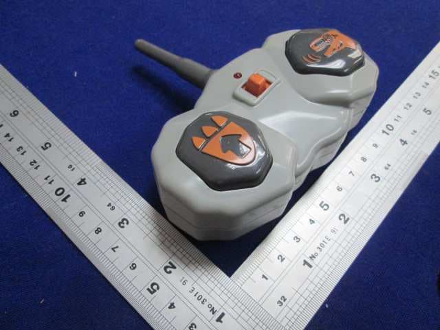
TB7DXTOY3492949M
Sep 16, 2015TOY RC DINOSAUR
Equipment Class
DXX - Part 15 Low Power Communication Device Transmitter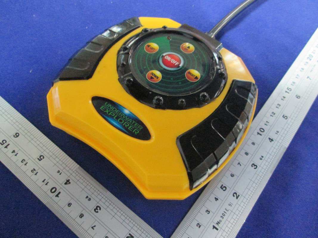
TB7DXTOYS3438749N
Sep 08, 2015TOY RC UNDERWATER EXPLORER
Equipment Class
DXX - Part 15 Low Power Communication Device Transmitter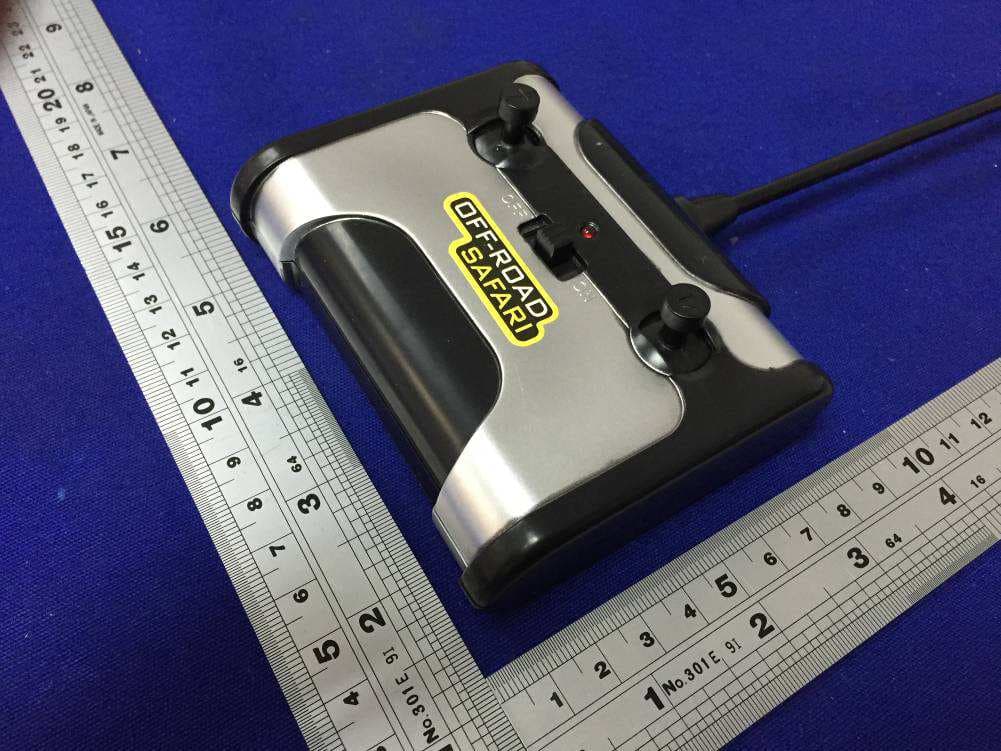
TB7DXTOYS3209027A
Jul 12, 2015TOY RC 4X4
Equipment Class
DXX - Part 15 Low Power Communication Device Transmitter