TBEPAVMini Camcorder
GOLDEN TECHNOLOGY CO., LTD.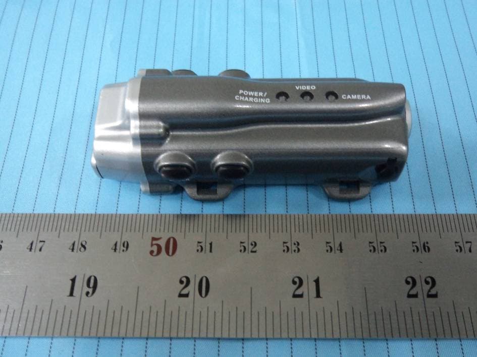
Click to zoom
Application Details
- Equipment Class
- JBP - Part 15 Class B Computing Device Peripheral
- Date of Grant
- Feb 06, 2012
- Application Purpose
- Original Equipment
- Date of Application
- Feb 06, 2012
- Equipment Note
- Mini Camcorder
- Company
- GOLDEN TECHNOLOGY CO., LTD.
- Country
- China
Documents & Files
Document Text
Text extracted from the exhibit documents filed with the FCC. Open a document above to read the original.
Users Manual
Mini Camcorder INSTRUCTION MANUAL I GENERAL DESCRIPTIONS Congratulations! You have chosen a great unique product, a hands-free, water-resistant, smallest & lightest Mini Camcorder. The mini size and super-light weight enable it to be easily mount to helmet, goggle, etc. It is definitely a great pal for sports / leisure filming & picturing. Besides, it is also a PC cam and removable disk. It is unique and advanced in: 3ATM water resistant (rain-proof & splash proof), great for beachfront sports, biking, trekking, skiing... NOT good for swimming, snorkeling, or any other under-water sports Patented water-resistant USB jack Laser pointing, what you see is what you get! Just follow the instruction, and it will be a great pal during your adventure. Product specifications 1. 4-in-1 Functions: Video Camcorder + Digital Camera + PC cam + Removable Disk (USB 2.0 high speed) 2. Video resolution: 800×600; frame rate: 25fps (frame per second); format: AVI 3. Camera resolution: 3.2 mega pixels (2048*1536); format: JPG 4. Date time stamp of videos and photos 5. Available memory sizes: 4GB / 8GB / 16GB 6. Remote control: for video-recording & photo-shooting 7. Power saving function: automatically power off when no operation in 10 minutes under standby mode 8. Working temperature: -10°C~50°C 9. Battery: rechargeable battery (3.7V, 400mAh), recharge through USB cable with computer 10. 3 LED lights: Red LED (POWER/CHARGING): light up means the power is on; flash once every 2 seconds means it is recharging; flash once every second means only 20% or less battery left; light off means it is power off Yellow LED (VIDEO): flash once every second means it is recording; light up means recording finished; light off means video stored in memory Blue LED (CAMERA): light up means taking a photo; light off means photo taken Blue and yellow LEDs flash alternatively once every second means Mini Camcorder is in pairing mode with remote control M0 M0 M0 M3 M1 M1 M2 M2 M2 M2 M2 M1 M1 M1 M0 (ON/OFF): long press M0 to turn on or turn off the Mini Camcorder M1 (CAMERA): short press M1 to take photos M2 (VIDEO): long press M2 to take videos M3 (Laser): short press M3 or long press M3 to turn on the laser beam to locate the filming or picturing targets. When the laser beam is on, short press M3 to turn it off. Without any operation, the laser beam will turn off in 10 seconds automatically. 11. 4 buttons on Mini Camcorder (main body): 12. 2 buttons on remote control R1 (CAMERA): Top button. Short press to take photos R2 (VIDEO): Side button. Short press to start or stop recording R1 R1 R1 R1 R2 R2 Note: short press means pressing the button once and then release the finger; long press means pressing and hold the button till operation finished. Accessories Below are the accessories in the packing, please check if they are complete. Mini CamcorderRemote Control Instruction Manual USB Cable 2pcs of Paddings Wrapping Straps Head Strap Push the lever downwards to the end Microphone Laser Microphone Camera lens II OPERATION Attach the Mini Camcorder to your goggle, helmet, etc, and adjust the shooting angle. Now, you can go ahead and make filming while enjoying sports / games. * Before you make any water-front filming, we suggest you detach the microphone first. Power off: long press button M0, red LED flashes 5 times and lights off, now power is off. Under standby mode, if there is no operation for 10 minutes, the Mini Camcorder will automatically power off. Note: When the temperature is low, it takes longer time to power on. When it is around 25°C, long press M0 for 2 seconds, the red LED will be on. When the temperature is around 0°C, long press M0 for 10 seconds. Power on / power off Power on: long press button M0, red LED lights up, then release the button and all the LEDs (red, yellow and blue) are on. After 2 seconds, yellow and blue LEDs will be off and red LED keeps on. Now the Mini Camcorder is ready for videos and photos. Capture Please power on the Mini Camcorder first. To capture, short press M1. Blue LED will be on for 4 seconds during each snapshot. Please keep your head still during photo taking to avoid blurry photos. If the memory is full, short press M1/R1 and the blue LED will flash once. Capture by remote control Please power on the Mini Camcorder first. To capture by remote control, short press R1 button. Blue LED will be on for 4 seconds during each snapshot. Please keep your head still during photo taking to avoid blurry photos. If the memory is full, short press M1/R1 and the blue LED will flash once. Record video Under standby mode, long press M2 and yellow LED will be on. After 6 seconds, yellow LED will start to flash and will keep flashing during recording.Long press M2 again to stop recording. Yellow LED (VIDEO) indicates recording status. Flash once every second means taking video; lights up means recording finished; lights off means video stored in memory. During video recording, short press M1 or R1 will stop the recording and take a photo. To start video recording again, please long press M2. If the memory is full, long press M2 or short press R2 and yellow LED will flash once. Record video by remote control Under any mode, short press R2 (VIDEO) on the remote and yellow LED will be on. After 6 seconds, yellow LED will start to flash and will keep flashing during recording. Short press R2 again to stop recording. Yellow LED (VIDEO) indicates recording status. Flash once every second means taking a video; lights up means recording finished; lights off means video stored in memory. During video recording, short press M1 or R1 will stop the recording and take a photo. To start video recording again, please short press R2. If the memory is full, long press M2 or short press R2 and yellow LED will flash once. Note: The viewing angle of this Mini Camcorder is 67°±5°. The deviation varies according to the proficiency of users. If the target is not with…
Text truncated - open the document above for the full version.
Cover Letter(s)
GOLDEN TECHNOLOGY CO., LTD No. 1232, Jiuzhou Road East, Zhuhai City, Guangdong Province, P. R. China Tel: +86-756-3325518 Fax: +86-756-3334079 FCC Confidential Authorization Date: 2012-01-30 FEDERAL COMMUNICATIONS COMMISSIONS Authorization and Evaluation Division 7435 Oakland Mills Road Columbia, MD 21046 Confidentiality Request regarding application for certification of FCC ID: TBEPAV Pursuant to Sections 0.457 and 0.459 of the Commission’s Rules, we hereby request confidential treatment of information accompanying this application as outlined below: Detailed Circuit Schematics of EUT--- (Long term) Block Diagram--- (Long term) Circuit Description--- (Long term) The above materials contain trade secrets and proprietary information not customarily released to the public. The public disclosure of these materials may be harmful to the applicant and provide unjustified benefits to its competitors. The applicant understands that pursuant to Section 0.457 of the Rules, disclosure of this application and all accompanying documentation will not be made before the date of the Grant for this application. Sincerely Yours, Signature: Susan Luo Sales Manager
External Photos
EXHIBIT B - EUT EXTERNAL PHOTOGRAPHS EUT – Front View EUT – Rear View
ID Label/Location Info
EXHIBIT A - FCC ID LABELING AND LOCATION FCC ID Label FCC ID Label Location The label shown shall be permanently affixed at a conspicuous location on the device and be readily visible to the user at the time purchase (Labeling requirements per 2.925)
Internal Photos
EXHIBIT C - EUT INTERNAL PHOTOGRAPHS EUT – Cover off View EUT – Main Board Top View 1 Receiver Antenna EUT – Main Board Top View 2 EUT – Main Board Bottom View EUT – RF Board Top View EUT – RF Board Bottom View EUT – Battery View EUT – USB Cable View
Test Report
Note: This test report is prepared for the customer shown above and for the device described herein. It may not be duplicated or used in part without prior written consent from Bay Area Compliance Laboratories Corp. This report must not be used by the customer to claim product certification, approval, or endorsement by NVLAP*, or any agency of the Federal Government. * This report contains data that are not covered by the NVLAP accreditation and are marked with an asterisk “★” (Rev.2) FCC PART 15 CLASS B TEST REPORT For GOLDEN TECHNOLOGY CO., LTD. No. 1232, Jiuzhou Road East, Zhuhai City, Guangdong Province, P. R. China FCC ID: TBEPAV Report Type: Original Report Product Type: Mini Camcorder Test Engineer: Yoully Ao Report Number: RSZ111230003-00 Report Date: 2012-02-02 Reviewed By: Lisa Zhu EMC Engineer Test Laboratory: Bay Area Compliance Laboratories Corp. (Shenzhen) 6/F, the 3rd Phase of WanLi Industrial Building, ShiHua Road, FuTian Free Trade Zone Shenzhen, Guangdong, China Tel: +86-755-33320018 Fax: +86-755-33320008 www.baclcorp.com.cn Bay Area Compliance Laboratories Corp. (Shenzhen) Report No.: RSZ111230003-00 FCC Part 15 Class B Page 2 of 13 TABLE OF CONTENTS GENERAL INFORMATION.......................................................................................................................................3 PRODUCT DESCRIPTION FOR EQUIPMENT UNDER TEST (EUT) .....................................................................................3 OBJECTIVE...................................................................................................................................................................3 RELATED SUBMITTAL(S)/GRANT(S).............................................................................................................................3 TEST FACILITY.............................................................................................................................................................3 SYSTEM TEST CONFIGURATION ..........................................................................................................................4 DESCRIPTION OF TEST CONFIGURATION......................................................................................................................4 EUT EXERCISE SOFTWARE..........................................................................................................................................4 EQUIPMENT MODIFICATIONS.......................................................................................................................................4 LOCAL SUPPORT EQUIPMENT LIST AND DETAILS........................................................................................................4 EXTERNAL I/O CABLE..................................................................................................................................................4 BLOCK DIAGRAM OF TEST SETUP................................................................................................................................5 SUMMARY OF TEST RESULTS ...............................................................................................................................6 FCC §15.107 – AC LINE CONDUCTED EMISSIONS .............................................................................................7 MEASUREMENT UNCERTAINTY....................................................................................................................................7 EUT SETUP..................................................................................................................................................................7 EMI TEST RECEIVER SETUP.........................................................................................................................................8 TEST EQUIPMENT LIST AND DETAILS...........................................................................................................................8 TEST PROCEDURE........................................................................................................................................................8 TEST RESULTS SUMMARY............................................................................................................................................8 TEST DATA..................................................................................................................................................................8 FCC §15.109 - RADIATED EMISSIONS .................................................................................................................11 MEASUREMENT UNCERTAINTY..................................................................................................................................11 EUT SETUP................................................................................................................................................................11 EMI TEST RECEIVER SETUP.......................................................................................................................................12 TEST PROCEDURE......................................................................................................................................................12 TEST EQUIPMENT LIST AND DETAILS.........................................................................................................................12 CORRECTED AMPLITUDE & MARGIN CALCULATION.................................................................................................12 TEST RESULTS SUMMARY..........................................................................................................................................12 TEST DATA................................................................................................................................................................13 Bay Area Compliance Laboratories Corp. (Shenzhen)…
Text truncated - open the document above for the full version.
Test Setup Photos
EXHIBIT D - TEST SETUP PHOTOGRAPHS Conducted Emission - Front View Conducted Emission - Side View Radiated Emission - Front View Radiated Emission – Rear View
Contact Information
Applicant
SUSAN LUO(SALES EXECUTIVE)
Test Firm
Bay Area Compliance Laboratory Corp. (Shenzhen)John Chan
Technical Specifications
| # | Rule Parts | Frequency Range | Power Output |
|---|---|---|---|
| 1 | 15B | - | - |
Other Applications from GOLDEN TECHNOLOGY CO., LTD.
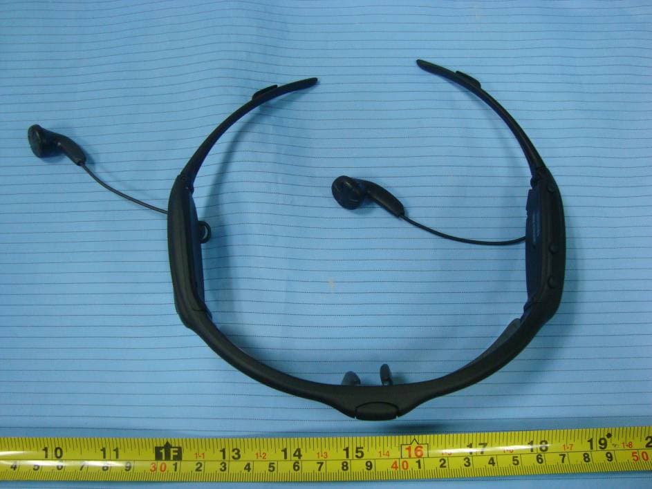
TBEOMV30
Jul 26, 2011Video Sunglasses
Equipment Class
JBP - Part 15 Class B Computing Device Peripheral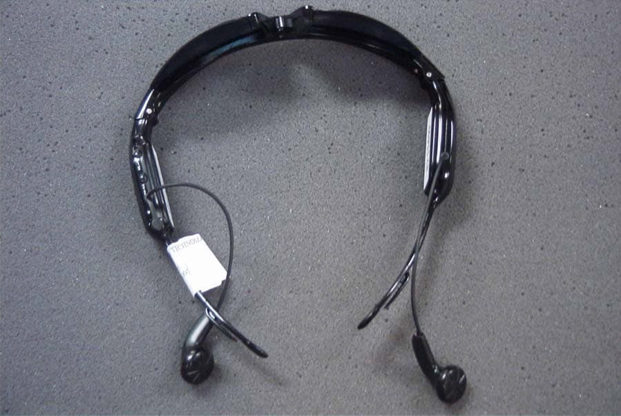
TBEOMMP3
May 24, 2005DC OPERATED MP3 SUNGLASSES
Equipment Class
JBP - Part 15 Class B Computing Device Peripheral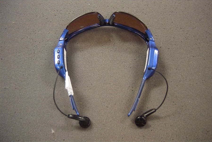
TBERMMP3
May 24, 2005DC OPERATED MP3 SUNGLASSES
Equipment Class
JBP - Part 15 Class B Computing Device Peripheral