TBO7525V1Hand-Held Micro Computer Bluetooth
APPLIED RFID SOLUTIONS INC.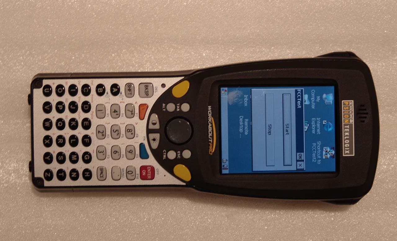
Click to zoom
Application Details
- Equipment Class
- DSS - Part 15 Spread Spectrum Transmitter
- Date of Grant
- Jul 17, 2005
- Application Purpose
- Original Equipment
- Date of Application
- Jul 17, 2005
- Equipment Note
- Hand-Held Micro Computer Bluetooth
- Frequency Range
- 2402.00000000 - 2480.00000000
- Company
- APPLIED RFID SOLUTIONS INC.
- Country
- Canada
Documents & Files
Document Text
Text extracted from the exhibit documents filed with the FCC. Open a document above to read the original.
Users Manual
WORKABOUT PRO M/C Hand-Held Computer Quick Start Guide March 11, 2004PN 8000025.A ISO 9001 Certified Quality Management System © Copyright 2004 by Psion Teklogix Inc., Mississauga, Ontario This document and the information it contains is the property of Psion Teklogix Inc., is issued in strict confidence, and is not to be reproduced or copied, in whole or in part, except for the sole purpose of promoting the sale of Psion Teklogix manufactured goods and services. Furthermore, this docu- ment is not to be used as a basis for design, manufacture, or sub-contract, or in any manner detrimental to the interests of Psion Teklogix Inc. All trademarks are the property of their respective holders. Return-To-Factory Warranty Psion Teklogix warrants a return-to-factory warranty for a period of one year. In some regions, the warranty exceeds this period. Please contact your local Psion Teklogix office for details. For a list of offices, refer to “Support Ser- vices & Worldwide Offices” on page 29. The warranty on Psion Teklogix manufactured equipment does not extend to any product that has been tam- pered with, altered, or repaired by any person other than an employee of an authorized Psion Teklogix service organization. See Psion Teklogix terms and conditions of sale for full details. Service When requesting service, please provide information concerning the nature of the failure and the manner in which the equipment was used when the fail- ure occurred. Type, model, and serial number should also be provided. Before returning any products to Psion Teklogix, please call the Customer Services Group for a Return Authorization number. Support Services Psion Teklogix provides a complete range of product support services to its customers. For detailed information, please refer to “Support Services & Worldwide Offices” on page 29. Disclaimer Every effort has been made to make this material complete, accurate, and up- to-date. Psion Teklogix Inc. reserves the right to make changes without notice and shall not be responsible for any damages, including but not limited to consequential damages, caused by reliance on the material presented, includ- ing but not limited to typographical errors. Psion Teklogix WORKABOUT PRO Hand-Held Computer Quick Start Guide 1 Table Of Contents 1. Basic Preparation . . . . . . . . . . . . . . . . . . . . . . . . . . . . . . . . . 3 1.1 Charging The Battery . . . . . . . . . . . . . . . . . . . . . . . . . . 3 1.2 Installing The Battery . . . . . . . . . . . . . . . . . . . . . . . . . . 3 1.3 Switching The Unit On. . . . . . . . . . . . . . . . . . . . . . . . . 4 1.4 Switching The Unit Off (Suspend) . . . . . . . . . . . . . . . . 4 2. Getting To Know The WORKABOUT PRO . . . . . . . . . . . . 5 2.1 Features. . . . . . . . . . . . . . . . . . . . . . . . . . . . . . . . . . . . . 5 2.2 The Battery . . . . . . . . . . . . . . . . . . . . . . . . . . . . . . . . . . 7 2.2.1 Battery Swap And Runtime . . . . . . . . . . . . . . . . 9 2.3 The Keyboard . . . . . . . . . . . . . . . . . . . . . . . . . . . . . . . . 9 2.3.1 Modifier Keys . . . . . . . . . . . . . . . . . . . . . . . . . . . 10 2.3.2 The Keys. . . . . . . . . . . . . . . . . . . . . . . . . . . . . . . 10 2.3.3 Adjusting The Keypad Backlight . . . . . . . . . . . . 12 2.4 The Display. . . . . . . . . . . . . . . . . . . . . . . . . . . . . . . . . . 12 2.4.1 Colour Display . . . . . . . . . . . . . . . . . . . . . . . . . . 13 2.4.2 Monochrome Display . . . . . . . . . . . . . . . . . . . . . 14 2.4.3 Calibrating The Touchscreen . . . . . . . . . . . . . . . 14 2.5 Indicators . . . . . . . . . . . . . . . . . . . . . . . . . . . . . . . . . . . 15 2.5.1 The LED . . . . . . . . . . . . . . . . . . . . . . . . . . . . . . . 15 2.5.2 Onscreen Indicators . . . . . . . . . . . . . . . . . . . . . . 16 2.5.3 Audio Indicators . . . . . . . . . . . . . . . . . . . . . . . . . 18 3. Navigating In Windows CE. . . . . . . . . . . . . . . . . . . . . . . . . . 19 3.1 Navigating A Touchscreen . . . . . . . . . . . . . . . . . . . . . . 19 3.2 Navigating Using The Keyboard . . . . . . . . . . . . . . . . . 19 2 Psion Teklogix WORKABOUT PRO Hand-Held Computer Quick Start Guide 3.3 The Startup Desktop . . . . . . . . . . . . . . . . . . . . . . . . . . . 20 3.3.1 Accessing Desktop Icons . . . . . . . . . . . . . . . . . . 20 3.3.2 The Taskbar. . . . . . . . . . . . . . . . . . . . . . . . . . . . . 21 3.4 The Start Menu . . . . . . . . . . . . . . . . . . . . . . . . . . . . . . . 21 3.5 Using A Dialogue Box . . . . . . . . . . . . . . . . . . . . . . . . . 26 4. General Maintenance. . . . . . . . . . . . . . . . . . . . . . . . . . . . . . . 28 4.1 Caring For The Touchscreen. . . . . . . . . . . . . . . . . . . . . 28 4.2 Cleaning The WORKABOUT PRO . . . . . . . . . . . . . . . 28 Approvals . . . . . . . . . . . . . . . . . . . . . . . . . . . . . . . . . . . . . . . . . 33 Safety Summary . . . . . . . . . . . . . . . . . . . . . . . . . . . . . . . . . . . . 35 Program License Agreements. . . . . . . . . . . . . . . . . . . . . . . . . . 38 Psion Teklogix WORKABOUT PRO Hand-Held Computer Quick Start Guide 3 1. Basic Preparation Important: All approval and safety information is outlined in the ‘WORKABOUT PRO Hand-Held Computer User Manual’ – part number 8000024. This manual is available on our web site www.psionteklogix.com through the Teknet extranet. It is important that you review all safety guidelines before charging a battery or operating a scanner. This quick start guide provides basic information on the operation and features of the Psion Teklogix WORKABOUT PRO M (Mono- chrome) and WORKABOUT PRO C (Colour) Hand-Held Compu- ter. For more detailed information, refer to the WORKABOUT PRO M/C Hand-Held Computer User Manual (PN 8000024) or the docu- mentation supplied with the application you are using. Typically, WORKABOUT PROs are configured at the factory and arrive ready for use. 1.1 Charging The Battery Batteries shipped from …
Text truncated - open the document above for the full version.
Attestation Statements
209 Dayton Street, Suite 205 Edmonds, WA 98020-3581 425 771-4482 425 486-1933 fax June 20, 2005 Federal Communications Commission Authorization and Evaluation Division C/O AmericanTCB, Inc. 6731 Whitter Avenue McLean, VA 22101 Re: Attestation of compliance FCC ID: TBO7525V1 Applicant: Applied RFID Solutions, Inc. Models: AP1pro – The Applied RFID Solutions AP1pro is a 13.56 MHz Intentional Radiator installed within a PSION Workabout Pro with it’s previously approved Bluetooth Intentional Radiator. Gentlemen: Spectrum Technology, Incorporated has tested the Applied RFID Solutions, Inc. 13.56 MHz RFID reader installed in a PSION, FCC ID: GM37525BT, Model: 7525C, Handheld Microcomputer with the referenced co-located Bluetooth transmitter. Measurements were made in accordance with the applicable requirements contained in the Parts 2 & 15.225, of Title 47, CFR and RSS-210, I-5, A-4. To the best of my knowledge, these tests were performed using the criteria established in ANSI C63.4 as applicable. Measurements were made to determine compliance of the 13.56 MHz, RFID module when installed in the Model: 7525C, Workabout Pro with existing Bluetooth Intentional Radiator. The co-located RFID module and Bluetooth transmitter are never operated simultaneously in the field and can not transmit at the same time. Therefore, no simultaneous transmit data was taken. Please refer to Grantee affidavit in Exhibit 13. The Test Reports referenced below demonstrate the equipment complies with the two applicable Part 15 Intentional Radiator limits. 1.) Test Report # 1 – Applied RFID Solutions, Inc. EMC measurements of the new FCC ID: TBO7525V1, 13.56 MHz, RFID module installed within a PSION Model: 7525C, Trade Name: Workabout Pro Handheld Microcomputer. EMC Test Report under Part 15.225, prepared by Spectrum Technology, Inc. for the new FCC ID: TBO7525V1. 2.) Test Report # 2 – PSION, OEM, EMC measurements for the FCC ID: GM37525BT, Model: 7525C, Workabout Pro Handheld Microcomputer with Bluetooth Intentional Radiator. Certified under, Part 15.247 rules applicable to FHSS and RSS-210 and amendments. The OEM test report data prepared by Compliance Certification Services for PSION Teklogix, Inc. is referenced for this application. Exhibit 2 1
Cover Letter(s)
Exhibit VIII Cover Letters New Certification Application FCC ID: TBO7525V1 Cover Letter 1.) Certification Action Requested Cover Letter 2.) Applied RFID Solutions, Inc., Request for Confidentiality under Part 0.459. Cover Letter 3.) Agent Authorization - Applied RFID Solutions Inc., letter authorizing Rod Munro of Spectrum Technology inc. to sign FCC Form 731 on their behalf. Cover Letter 4.) Grantee attestation regarding a) no RFID operation while in AC charging cradle and b) no RFID simultaneous transmit with Bluetooth Intentional Radiator.
Cover Letter(s)
Bluetooth Declaration Per FCC 15.247 Requirements 1 Output power and channel separation of a Bluetooth device in the different operating modes: The different operating modes (data-mode, acquisition-mode) of a Bluetooth device don’t influence the output power and the channel spacing. There is only one transmitter which is driven by identical input parameters concerning these two parameters. Only a different hopping sequence will be used. For this reason the check of these RF parameters in one op-mode is sufficient. 2 Frequency range of a Bluetooth device: Hereby we declare that the maximum frequency of this device is: 2402 – 2480 MHz. This is according the Bluetooth Core Specification V 1.0B (+ critical errata) for devices which will be operated in the USA. This was checked during the Bluetooth Qualification tests (Test Case: TRM/CA/04-E). Other frequency ranges ( e.g. for Spain, France, Japan) which are allowed according the Core Specification are not supported by this device. 3 Co-ordination of the hopping sequence in data mode to avoid simultaneous occupancy by multiple transmitters: Bluetooth units which want to communicate with other units must be organized in a structure called piconet. This piconet consist of max. 8 Bluetooth units. One unit is the master the other seven are the slaves. The master co-ordinates frequency occupation in this piconet for all units. As the master hop sequence is derived from it’s BD address which is unique for every Bluetooth device, additional masters intending to establish new piconets will always use different hop sequences. 4 Example of a hopping sequence in data mode: Example of a 79 hopping sequence in data mode: 40, 21, 44, 23, 42, 53, 46, 55, 48, 33, 52, 35, 50, 65, 54, 67, 56, 37, 60, 39, 58, 69, 62, 71, 64, 25, 68, 27, 66, 57, 70, 59, 72, 29, 76, 31, 74, 61, 78, 63, 01, 41, 05, 43, 03, 73, 07, 75, 09, 45, 13, 47, 11, 77, 15, 00, 64, 49, 66, 53, 68, 02, 70, 06, 01, 51, 03, 55, 05, 04 5 Equally average use of frequencies in data mode and behaviour for short transmissions: The generation of the hopping sequence in connection mode depends essentially on two input values: 1. LAP/UAP of the master of the connection 2. Internal master clock The LAP (lower address part) are the 24 LSB’s of the 48 BD_ADDRESS. The BD_ADDRESS is an unambiguous number of every Bluetooth unit. The UAP (upper address part) are the 24 MSB’s of the 48 BD_ADDRESS. The internal clock of a Bluetooth unit is derived from a free running clock which is never adjusted and is never turned off. For synchronisation with other units only offset are used. It has no relation to the time of the day. Its resolution is at least half the RX/TX slot length of 312.5 μs. The clock has a cycle of about one day (23h30). In most case it is implemented as 28 bit counter. For the deriving of the hopping sequence the entire LAP (24 bits), 4 LSB’s (4 bits) (Input 1) and the 27 MSB’s of the clock (Input 2) are used. With this input values different mathematical procedures (permutations, additions, XOR-operations) are performed to generate the sequence. This will be done at the beginning of every new transmission. Regarding short transmissions the Bluetooth system has the following behaviors: The first connection between the two devices is established, a hopping sequence was generated. For transmitting the wanted data the complete hopping sequence was not used. The connection ended. The second connection will be established. A new hopping sequence is generated. Due to the fact that the Bluetooth clock has a different value, because the period between the two transmission is longer (and it cannot be shorter) than the minimum resolution of the clock (312.5 μs). The hopping sequence will always differ from the first one. 6 Receiver input bandwidth and behaviors for repeated single or multiple packets: The input bandwidth of the receiver is 1 MHz. In every connection one Bluetooth device is the master and the other one is the slave. The master determines the hopping sequence (see chapter 5). The slave follows this sequence. Both devices shift between RX and TX time slot according to the clock of the master. Additionally the type of connection (e.g. single or multislot packet) is set up at the beginning of the connection. The master adapts its hopping frequency and its TX/RX timing according to the packet type of the connection. Also the slave of the connection will use these settings. Repeating of a packet has no influence on the hopping sequence. The hopping sequence generated by the master of the connection will be followed in any case. That means, a repeated packet will not be send on the same frequency, it is send on the next frequency of the hopping sequence. 7 Dwell time in data mode The dwell time of 0.3797s within a 30 second period in data mode is independent from the packet type (packet length). The calculation for a 30 second period is a follows: Dwell time = time slot length * hop rate / number of hopping channels *30s Example for a DH1 packet (with a maximum length of one time slot) Dwell time = 625 μs * 1600 1/s / 79 * 30s = 0.3797s (in a 30s period) For multislot packet the hopping is reduced according to the length of the packet. Example for a DH5 packet (with a maximum length of five time slots) Dwell time = 5 * 625 μs * 1600 * 1/5 *1/s / 79 * 30s = 0.3797s (in a 30s period) This is according the Bluetooth Core Specification V 1.0B (+ critical errata) for all Bluetooth devices. There for all Bluetooth devices comply with the FCC dwell time requirement in data mode. This was checked during the Bluetooth Qualification tests. The Dwell time in hybrid mode is measured and stated in the test report. 8 Channel Separation in hybrid mode The nominal channel spacing of the Bluetooth system is 1Mhz independent of the operating mode. The maximum “initial carrier frequency tolerance” which is allowed for Bluetooth is fcenter = 75 kHz. This was checked during the Bluetooth Qualification tests (Test Case:…
Text truncated - open the document above for the full version.
External Photos
Applicant: Applied RFID Solutions, Inc. FCC ID: TBO7525V1 Front View Back View Exhibit 3 External Photos Applicant: Applied RFID Solutions, Inc. FCC ID: TBO7525V1 Bottom View Exhibit 3 External Photos Applicant: Applied RFID Solutions, Inc. FCC ID: TBO7525V1 Rear View Battery Cover Removed Rear View Only NOT intended for FCC ID Label - see Exhibit 1 Exhibit 3 External Photos
ID Label/Location Info
Applicant: Applied RFID Solutions, Inc. FCC ID: TBO7525V1 EXHIBIT 1. LIST OF EXHIBITS and FCC IDENTIFICATION LABEL LIST OF EXHIBITS DESCRIPTION EXHIBITS REFERENCE I. FCC Identification label Information 1 2.1033 (b) 7 & 2.925 & General Information 1A 1. Production Plans 2.1031 2. Application References N/A II. Certification Data 2 III. External Photographs 3 2.1033 (b) 7 IV. Block Diagrams (Circuit Diagrams) confidential 4 2.1033 (b) 5 V. Schematic Diagrams confidential 5 2.1033 (b) 5 VI Test Report 1 6 2.1033 (b) 6 Part 15.225 – EMC Test Report, RFID 13.56 MHz transmitter, the Applied RFID Solutions, Inc., FCC ID: TBO7525V1, Model: AP1pro 1) RF Power Output (2.1046) 2) Transmitter Radiated Spurious Emissions (2.1053) VI Test Report 2 6 2.1033 (b) 6 Part 15.247 – FHSS, Complete OEM Test Report prepared by CCS, EMC Test Report for the previously Certified PSION Teklogix, Inc., Bluetooth, Intentional Radiator, FCC ID: GM37525BT, Model: 7525C Workabout Pro VII. Test Set-up Procedures 7 2.1041 VIII. Instruction Manual 8 2.1033 (b) 3 IX. Internal Photographs 9 2.1033 (b) 7 X. Part List and Tune Up Procedures confidential 10 2.1033 XI. MPE RF Exposure Information 11 2.1093,15.247(b)4 XII. Operational Description confidential 12 2.1033(b)1,2,4,8 Antenna Requirements (Note: antenna permanently attached) 12 15.203 XIII. Cover Letter, Certification Action Requested 13 Cover Letter, Request for Confidentiality 13 Cover Letter, Authorization to sign FCC Form 731 13 Exhibit 1 Applicant: Applied RFID Solutions, Inc. FCC ID: TBO7525V1 EXHIBIT 1. FCC IDENTIFICATION LABEL & LOCATION FCC and IC number will go here The Part 15.19 Information will go here The Part 15.19 Users statement follows: “This device complies with part 15 of the FCC Rules. Operation is subjected to the following two conditions: (1) This device may not cause harmful interference, and (2) this device must accept any interference received, including interference that may cause undesired operation” This Class B digital apparatus complies with Canadian ICES-003. Cet appareil numérique de la classe B est conforme à la norme NMB-003 du Canada Facsimile FCC Identifier Label A facsimile of the FCC Identification label required under section: 47 CFR 2.1033(c) 11 , is located on following page for the FCC ID: TBO7525V1. Exhibit 1 Applied RFID Solutions Inc . FCC ID: TBO7525V1 IC: XXXXXXXX
Internal Photos
Applicant: Applied RFID Solutions, Inc. FCC ID: TBO7525V1 INTERNAL PHOTOGRAPHS Front view component side - RFID pcb EXHIBIT 9 Internal Photos Applicant: Applied RFID Solutions, Inc. FCC ID: TBO7525V1 Back view foil side - RFID pcb showing the printed loop antenna EXHIBIT 9 Internal Photos
Test Report
Compliance Certification Services Inc. Report No: B40304404-RP ID No.: GM37525BT Date of Issue: May 6, 2004 Note: This report shall not be reproduced except in full, without the written approval of Compliance Certification Services Inc. This document may be altered or revised by Compliance Certification Services Inc. personnel only, and shall be noted in the revision section of the document. Page 1 of 51 FCC 47 CFR PART 15 SUBPART C TEST REPORT For Psion Teklogix Inc. Hand-held Micro-computer Model: 7525C Trade Name: WORKABOUT PRO Prepared for Psion Teklogix Inc. 2100 Meadowvale Blvd, Mississauga, Ontario, L5N 7J9, Canada Prepared by Compliance Certification Services Inc. No. 81-1, Lane 210, Bade Rd. 2, Luchu Hsiang, Taoyuan Hsien, (338) Taiwan, R.O.C. TEL: 886-3-324-0332 FAX: 886-3-324-5235 Compliance Certification Services Inc. Report No: B40304404-RP ID No.: GM37525BT Date of Issue: May 6, 2004 Page 2 TABLE OF CONTENTS 1. TEST RESULT CERTIFICATION....................................................................................................3 2. EUT DESCRIPTION ...........................................................................................................................4 3. TEST METHODOLOGY ....................................................................................................................5 3.1 EUT CONFIGURATION........................................................................................................................5 3.2 EUT EXERCISE....................................................................................................................................5 3.3 GENERAL TEST PROCEDURES.............................................................................................................5 3.4 FCC PART 15.205 RESTRICTED BANDS OF OPERATIONS........................................................6 3.5 DESCRIPTION OF TEST MODES...........................................................................................................6 4. INSTRUMENT CALIBRATION........................................................................................................7 5. FACILITIES AND ACCREDITATIONS ..........................................................................................8 5.1 FACILITIES .........................................................................................................................................8 5.2 EQUIPMENT........................................................................................................................................8 5.3 LABORATORY ACCREDITATIONS AND LISTING..................................................................................8 5.4 TABLE OF ACCREDITATIONS AND LISTINGS.......................................................................................9 6. SETUP OF EQUIPMENT UNDER TEST .......................................................................................10 6.1 SETUP CONFIGURATION OF EUT.......................................................................................................10 6.2 SUPPORT EQUIPMENT ...............................................................................................................10 7. FCC PART 15.247 REQUIREMENTS.............................................................................................11 7.1 PEAK POWER....................................................................................................................................11 7.2 PEAK POWER SPECTRAL DENSITY....................................................................................................12 7.3 BAND EDGES MEASUREMENT ................................................................................................15 7.4 FREQUENCY SEPARATION.......................................................................................................20 7.5 NUMBER OF HOPPING FREQUENCY ......................................................................................22 7.6 TIME OF OCCUPANCY (DWELL TIME)...................................................................................24 7.7 RADIO FREQUENCY EXPOSURE........................................................................................................32 7.8 SPURIOUS EMISSIONS ................................................................................................................33 7.9 POWERLINE CONDUCTED EMISSIONS...............................................................................................46 APPENDIX 1 PHOTOGRPHS OF TEST SETUP .................................................................................50 Compliance Certification Services Inc. Report No: B40304404-RP ID No.: GM37525BT Date of Issue: May 6, 2004 Page 4 2. EUT DESCRIPTION Product Hand-held Micro-computer Trade Name WORKABOUT PRO Model Number 7525C Model Discrepancy N/A Bluetooth Model No. Zeevo TC2001 Power Supply Powered from AC/DC power adapter Model Number: LSE9912B0515 Input: AC 100~240V, 50/ 60 Hz, 0.5A Output: DC 5V, 3.0A Frequency Range 2402 MHz ~ 2480 MHz Transmit Power -4.24dBm Modulation Technique Frequency Hopping Spread Spectrum (FHSS) Number of Channels 79 Channels Antenna Designation PCB Antenna Antenna Gain 3.94 dBi (Max) Temperature Range 0 ~ +50°C Note: This submittal(s) (test report) is intended for FCC ID: GM375225BT filing to comply with Section 15.207, 15.209 and 15.249 of the FCC Part 15, Subpart C Rules. Compliance Certification Services Inc. Report No: B40304404-RP ID No.: GM37525BT Date of Issue: May 6, 2004 Page 5 3. TEST METHODOLOGY The tests documented in this report were performed in accordance with ANSI C63.4 and FCC CFR 47 2.1046, 2.1047, 2.1049, 2.1051, 2.1053, 2.1055, 2.1057, 15.207, 15.209 and 15.247. 3.1 EUT CONFIGURATION The EUT configuration for testing is installed on RF field strength measurement to meet the Commissions requirement and operating in a manner that intends to maximize its emission characteristics …
Text truncated - open the document above for the full version.
Test Setup Photos
Compliance Certification Services Inc. Report No: B40304404-RP ID No.: GM375225BT Date of Issue: May 6, 2004 Page 50 APPENDIX 1 PHOTOGRPHS OF TEST SETUP Radiated Emission Set up Photos Compliance Certification Services Inc. Report No: B40304404-RP ID No.: GM375225BT Date of Issue: May 6, 2004 Page 51 Conducted Emission Set Up Photos
Contact Information
Applicant
Avihu (Avi) Nachmani(President)
Technical Contact
Spectrum Technology, Inc.Rod Munro
[email protected]425-771-4482
209 Dayton Street, Suite 205 · Edmonds, Washington · United States
Test Firm
Spectrum Technology Inc.Rod Munro
Technical Specifications
| # | Rule Parts | Frequency Range | Power Output |
|---|---|---|---|
| 1 | 15C | 2.40 GHz - 2.48 GHz | 400.00 µW |
Other Applications from APPLIED RFID SOLUTIONS INC.

TBOPRFDV12
Dec 14, 2009Proxima RF Desktop
Equipment Class
DXX - Part 15 Low Power Communication Device Transmitter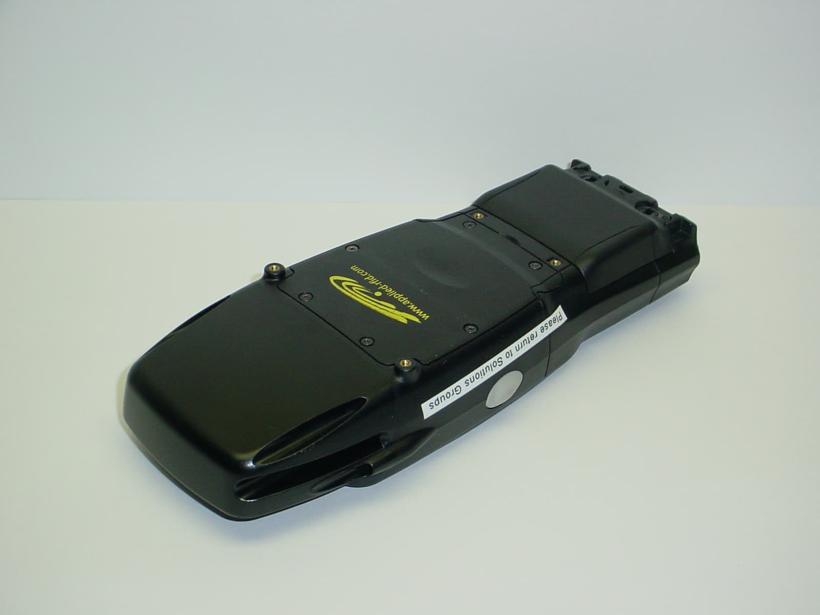
TBO7527SBTAVXB
Sep 18, 2007WORKABOUT PRO G2
Equipment Class
DXT - Part 15 Low Power Transceiver, Rx Verified