TEYTH307Handheld Two Way Radio
ABELL INDUSTRIES CO., LTD.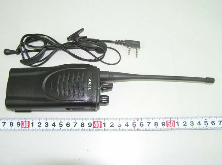
Click to zoom
Application Details
- Equipment Class
- TNF - Licensed Non-Broadcast Transmitter Held to Face
- Date of Grant
- Jul 07, 2005
- Application Purpose
- Original Equipment
- Date of Application
- Jul 07, 2005
- Equipment Note
- Handheld Two Way Radio
- Frequency Range
- 450.00000000 - 470.00000000
- Company
- ABELL INDUSTRIES CO., LTD.
- Country
- China
Documents & Files
Document Text
Text extracted from the exhibit documents filed with the FCC. Open a document above to read the original.
Users Manual
INSTRUCTION MANUAL FM TRANSCEIVER / TWO WAY RADIO MODEL: TH-307 ABELL ELECTRONICS, INC. THANK YOU! Thank you for choosing Abell transceiver. We strive to make this transceiver easy to use and dependable so it could be a useful tool for you. MODELS COVERED BY THIS MANUAL TH-307: UHF/VHF FM Transceiver (Two-Way Radio) PRECAUTIONS 1. Do not operate this transceiver in any areas that may require the product to remain off. Those areas may be in hospital or on airplane, etc. 2. Do not push the PTT button when antenna is not loaded or when the unit is being charged. 3. Do not modify this transceiver for any reason. Modifying this transceiver causes losing the warranty. 4. Do not leave the transceiver under direct sunlight for long periods, close to heating appliances, in excessively dusty, humid areas, nor on unstable surfaces. 5. Do not leave this transceiver in the reachable area of air bags in a car. 6. If an abnormal odor or smoke is detected coming from the transceiver, turn it off immediately and remove the optional battery pack from the transceiver. Contact your ABELL dealer. 7. The battery pack must be disposed of properly. Do not connect the battery terminals or dispose of by fire. Do not open the battery pack. 8. This transceiver is rain proof, but do not immerse into water. 9. Skin maybe slighted burned if touched by a damaged radio antenna. One or more of the following statements may be applicable: WARNING Government Law prohibits operating unlicensed two-way radios within the areas under governmen t control. Illegal operation is punishable by fine or imprisonment or both. Refer Service to licensed technician only. SAFETY WARNING: Turn off your transceiver, and do not change/charge your battery pack in stormy lightening weather or in explosive environments, such as gas station, or any area with explosive dust, fumes, etc. A QUICK GUIDE OF USING THIS TRANSCEIVER Here is a quick guide about how to start using it. 1. Fully Charge the battery pack. Load the antenna and battery pack to the transceiver. 2. Turn the power switch on, select a channel 3. Hold down PTT to talk, release PTT to listen. CONTENTS THANK YOU! ...............................................................1 MODELS COVERED BY THIS MANUAL ........................ Inside Front Cover WARNING ..........................................Inside Front Cover SAFETY WARNING ..........................................Inside Front Cover PRECAUTIONS ............................................................ii FCC WARNINGS..............................i A QUICK GUIDE OF USING THIS TRANSCEIVER ..............................i UNPACKING AND CHECKING ........................1 PREPARATION...............................................................3 IMPORTANT INFORMATION ABOUT BATTERY CHARGING .................. INSTALL/REMOVE THE BATTERY PACK.................. INSTALL THE ANTENNA.................. INSTALL THE SPEAKER-MICROPHONE.................. INSTALL THE BELT CLIP.................. KNOWING THIS TRANSCEIVER ...................................................... BASIC FUNCTIONS & FEATURES..................................................................... CALLING & RECEIVING..................................................................... CTCSS & DCS ..................................................................... FCC WARNING Caution: Changes or modifications to this unit not expressly approved by the party responsible for compliance will void the user’s authority to operate the equipment. Any change to the equipment will void FCC grant. NOTE: This equipment has been tested and found to comply with the limits for a device, pursuant to part 15 of the FCC Rules. These limits are designed to provide reasonable protection against harmful interference in a residential installation. This equipment generates, uses and can radiate radio frequency energy and, if not installed and used in accordance with the instructions, may cause harmful interference to radio communications. However, there is no guarantee that interference will not occur in a particular installation. If this equipment does cause harmful interference to radio or television reception, which can be determined by turning the equipment off and on, the user is encouraged to try to correct the interference by one or more of the following measures: --Reorient or relocate the receiving antenna. --Increase the separation between the equipment and receiver. --Connect the equipment into an outlet on a circuit different from that to which the receiver is connected. --Consult the dealer or an experienced radio/TV technician for help. INFORMATION TO THE DIGITAL DEVICE USER REQUIRED BY THE FCC This equipment has been tested and found to comply with part 90 of the FCC Rules. TIME OUT TIMER(TOT) ..................................................................... BUSY CHANNEL LOCKOUT..................................................................... LOW BATTERY WARNING..................................................................... AUTOMATIC POWER SAVE ..................................................................... SCAN OPERATION (AVAILABLE IN TH307E) ................................................... TROUBLESHOOTING ..................................................................... SPECIFICATIONS..................................................................... FRENQUENCY CHART..................................................................... UNPACKING AND CHECKING Carefully unpack it. We recommend that you check the items listed below before discarding the packing material. If any damage occurred during shipment, file a claim with the carrier immediately. Item Qty Transceiver 1 Antenna 1 Belt-clip, Screw set 1 Instruction manual 1 Warranty card 1 Battery (may be packed in separate box) 1 Charger (may be packed in separate box) 1 PREPARATION Important Information About Battery Charging 1. The battery pack is not charged at the factory. Please charge it bef…
Text truncated - open the document above for the full version.
External Photos
EXHIBIT B - EUT EXTERNAL PHOTOGRAPHS EUT – Front View EUT – Rear View
ID Label/Location Info
EXHIBIT A - FCC ID LABELING AND LOCATION Proposed FCC ID Labeling Proposed FCC ID Location Battery Cover Removed View of EUT / Proposed Label Location ATTENTION! Restricted to occupational use to satisfy FCC RF exposure limits. See users manual for operating requirements. FCC ID: TEYTH307 Model: TH-307
Internal Photos
EXHIBIT B - EUT INTERNAL PHOTOGRAPHS EUT – Uncovered View (1) EUT – Uncovered View (2) EUT – Uncovered View (3) EUT – Mainboard View (1) EUT – Mainboard View (2)
Operational Description
CIRCUIT DESCRIPTION 1、Frequency configuration The receiver utilizes double conversion.The first IF is 38.85MHZ and the second IF is 450kHz. The first local oscillator signal is supplied from the PLL circuit. The PLL circuit in the transmitter generates the necessary frequencies.Fig.1 shows the frequencies. Fig.1 Frequency configuration 2 、 Receiver The receiver is double conversion superheterodyne, designed to operate in the frequency range of 150 to 174MHz( M type),136 to 150MHz(M2 type). The frequency configuration is shown in Fig.1 (1)Front-end RF amplifier An incoming signal from the antenna is applied to an RF amplifier (Q203) after passing through a transmit/receive switch circuit (D102 and D103 are off)and a band pass filter L208,L209 and L210).After the signal is amplified (Q203), the signal is filtered through a band pass filter (L203 and L214)to eliminate unwanted signals before it is passed to the first mixer .Band pass filters (L208,L209,L210,L203 and L214)have varactor diodes (D203,D204,D206,D202 and D2010. The voltage of these diodes are controlled by to track the MPU(IC403) center frequency of the band pass filter.(See.Fig2). Fig.2 Receiver section configuration (2)First Mixer The signal from the RF amplifier is heterodyned with the first local oscillator signal from the PLL frequency synthesizer circuit at the first mixer (Q202)to create a 38.85MH first intermediate frequency (1st IF)signal.The first IF signal is then fed through two monolithic crystal filters(MCFs:XF200)to further remove spurious signals. (3) IF amplifier The first IF signal is amplified by Q201,and then enters IC200(FM processing IC).The signal is heterodyned again with a second local oscillator signal within IC200 to create a 450kHz second IF signal. The second IF signal is then fed through a 450kHz ceramic filter (CF200) to further eliminate unwanted signals before it is amplified and FM detected in IC200. XF200: Item Rating Nominal center frequency 38.850MHz Pass band width +/-5.0 kHz or more at 3dB 40dB stop band width +/-20.0kHz or less Ripple 1.0dB or less Insertion loss 4.0dB or less Guaranteed attenuation 80dB or more at 10-910kHz Terminal impedance 610 ohm/3PF CF200: Item Rating Nominal center frequency 450MHz 6dB band width +/-6.0 kHz or more 50dB band width +/-12.5kHz or less Ripple 2.0dB or less at 10+/-4kHz Insertion loss 6.0dB or less Guaranteed attenuation 35.0dB or more at 10+/-100kHz Terminal impedance 2.0 ohm (4)AF amplifier The recovered AF signal obtained from IC200 is amplified by IC300(1/4), filtered by the IC300 low-pass filter (2/4)and IC300 high-pass filter (3/4)and (4/4),and de-emphasized by R303 and C306. The AF signal is then passed through a WIDE/NARROW switch (Q303),The processed AF signal passes through an AF volume control and is amplified to a sufficient level to drive a loud speaker by an AF power amplifier(IC302). (5) Squelch Part of the AF signal from the IC enters the FM IC again, and the noise component is amplified and rectified by a filter and an amplifier to produce a DC voltage corresponding to the noise level. The DC signal from the FM IC goes to the analog port of the microprocessor (IC403),IC403 determines whether to output sounds from the speaker by checking whether the input boltage is higher or lower than the preset value. To output sounds from the speaker,IC403 sends a high signal to the MUTE and AFCO lines and turn IC302 on through Q304,Q305,Q306andQ307.(See Fig.3) Fig.3 AF Amplifier and squelch (6)Receive signaling QT/DQT 300 Hz and higher audio frequencies of the output signal from IF IC are cut by a low-pass filter (IC301),The resulting signal enters the microprocessor(IC403).IC403 determines whether the QT or DQT matches the preset value, and controls the MUTE and AFCO and the speaker output sounds according to the squelch results. 3、PLL frequency synthesizer The PLL circuit generates the first local oscillator signal for reception and the RF signal for transmission. (1) PLL The frequency step of the PLL circuit is 5 or 6.25kHz.A 12.8MHz reference oscillator signal is divided at IC1 by a fixed counter to produce the 5 or 6.25kHz reference frequency, The voltage controlled oscillator(VCO)output signal is buffer amplified by Q6,then divided in IC1 by a dual-module programmable counter ,The divided signal is compared is phase with the 5 or 6.25kHz reference signal in the phase comparator in IC1. The output signal from the phase comparator is filtered through a low-pass filter and passed to the VCO to control the oscillator frequency.(See Fig.4) Fig.4 PLL circuit (2) VCO The operating frequency is generated by Q4 in transmit mode and Q3 in receive mode. The oscillator frequency is controlled by applying the VCO control voltage, obtained from the phase comparator, to the varactor diodes (D2 and D4 in transmit mode and D1 and D3 in receive mode). The T/R pin is set high in receive mode causing Q5 and Q7 to turn Q4 off, and turn Q3 on .The T/R pin is set low in transmit mode .The outputs from Q3 and Q4 are amplified by Q6 and sent to the buffer amplifiers. (3)UNLOCK DETECTOR If a pulse signal appears at the LD pin of Lc1, an unlock condition occurs, and C1 causes the voltage applied to the UL pin of the microprocessor to go low. When the microprocessor detects this condition, the transmitter is disabled, ignoring the push-to-talk switch input signal. (See Fig.5) Fig.5 Unlock detector circuit 4 、 Transmitter (1)Transmit audio The modulation signal from the microphone is amplified by IC500(1/2), passes through a preemphasis circuit , and amplified by the other IC500(1/2)to perform IDC operation. The signal then passes through a low-pass filter (splatter filter)(Q501 and Q502)and cuts 3kHz and higher frequencies. The resulting signal goes to the VCO through the VCO modulation terminal for direct FM modulation.(See Fig.6) Fig.6 Transmit audio QT/DQT (2)QT/DQT encoder A necessary signal for QT/DQT encoding is generated by IC403 and FM-modulated to the PLL refere…
Text truncated - open the document above for the full version.
Parts List/Tune Up Info
Tune-Up Procedure The built-in Channels are 15 channels +1 scan channel The range of frequency is 450-470MHz 1. Both channels (15 channel+1 scan channel) can be preset by the computer with programming software. 2. Install the software we supplied in the computer. 3. Connect the transceiver with the PC by programming cable. 4.Open the software, Click on "Test Channel Setting", Select a channel, Setting the data in the “Edit Channel" .You can change the frequency by input the value or press “Æ” or “Å” on the keyboard to add or deduct the value. Click "OK"/“Delete" to confirm/delete the setting. 5. The procedure of the adjusting power is similar with point 4(above). Required Test Equipment 1. Stabilized Power supply ①The supply voltage can be changed between 5V and 18V, and the current is 3A or more. ② The standard voltage is 7.5V. 2. DC Ammeter ①Class 1 ammeter (17 ranger and other features). ②The full scale can be set to either 300mA or 3A. ③A cable of less internal loss must be used. 3. Frequency Counter (f.counter) ①Frequencies of up to 1GHz or so can be measured. ②The sensitivity can be changed to 500MHz or below ,and measurements are highly stable and accurate (0.2ppm or so). 4. Power Meter ①Measurable frequency :Up to 500MHz. ②Impedance : 50Ω,unbalanced ③Measuring range :Full scale of 10W or so ④A standard cable (5D2W 1m) must be used. 5. RF Voltmeter (RF V.M) ①Measurable frequency : Up to 500MHz or so. 6. Linear Detector ①Measurable frequency : Up to 500MHz or so. ②Characteristics are flat ,and CN is 60Db or more. 7. Digital Voltmeter ①Voltage range : FS=18V or so ②Input resistance : 1MΩ or more. 8. Oscilloscope ①Measuring range : DC to 30MHz ②Provides highly accurate measurements for 5 to 25MHz. 9. AF Voltmeter (AF V.M) ①Measurable frequency :50Hz to 1MHz ②Maximum sensitivity : 1mV or more 10. Spectrum Analyzer ①Measuring range : DC to 1GHz or more 11. Standard Signal Generator (SSG) ①Maximum frequency : 500MHz or more ②Output :-133dBm/0.05μV to 7dBm/501Mv ③Output impedance :50Ω 12. Tracking Generator ①Center frequency : 50kHz to 500MHz ②Frequency deviation : ±35MHz ③Output voltage : 100mV or more 13. Dummy Load ①8Ω, 3W or more 14. AF Generator (AG) ①Frequency range : 100Hz to 100kHz ②Output : 0.5mV to 1V 15. Distortion Meter ①Measurable frequency :30Hz to 100kHz ②Input level : 50m V to 10Vrms ADJUSTMENT FREQUENCY LIST Destination M CH TX f(MHz) RX f(MHz) Center 460.025 Low 450.025 Hi 469.975 Remarks z Connect the transceiver to the PC z Send the channel data to the transceiver,then backup the data. z Program the adjustment frequencies which are in the list, into the transceiver. Note: Remember to reload the channel data you backed up after making the transceiver. 1. Jig(chassis)for adjustment 2. Use the jig as follows: 1. Insert the coaxial antenna connector into the jig. 2. Place the unit on the jig and fix it with 12 screws.① 3. Solder the antenna terminal to the terminal of the unit. Notes : Supply power from an external power supply. Relay terminal: + Jig (chassis): - ADJUSTMENT Squelch Level, Transmit frequency, DQT Balance, RF Power, QT Deviation, DQT Deviation, Battery Level Section common to the transmitter and receiver(VCO) Measurement Adjustment Item Condition Test equipment Terminal Parts Method Specification s/remarks 1.Band-pass filter 1).CH:RX center 2).Tra generator output-40dBm Connect the spectrum analyzer to TP2 terminal. Tra generator Spectrum analyzer ANT TP2 TC201 Adjust the frequency so that it becomes the spectrum waveform shown in Fig.1. 2.AF level 1).CH:RX center SSG output:-53dBm(501μV) MOD:1KHz DEV :±3.0KHz(Wide) : ±1.5KHz(Narrow) L212 Adjust to the MAX AF level 3.Sensitivity 1)CH:RX center CH:RX LO CH:RX Hi SSG ouput:-116dBm(0.35μV) MOD:1kHz DEV :±3.0kHz(Wide) ±1.5kHz(narrow) Check SINAD:12dB or higher 1)CH:RX center MONI:ON 2)Level 9 SSG output:-117dBm(0.36 μ V) Level 9 Adjust to close the squelch. The squelch must be closed. 4.Squelch Level (PC MODE) 3)level 3 SSG output:-125dBm(0.126μV) SSG Oscilloscope AF.V.M Distortion meter ANT SP PC key Level 3 Adjust to close the squelch The squelch must be closed. Measurement Adjustment Item Condition Test equipment Termina l Parts Metho d Specifications/remarks 1. Setting 1)Power supply voltage Battery teriminal:7.5V 1)CH:TX high TC1 3.8V ±0.1V 2) CH:RX high TC2 3.8V ±0.1V 3) CH:TX low 2.VCO lock voltage 4) CH:RX low Digital voltmeter CV Check More than 0.7V Measurement Adjustment Item Condition Test equipment Terminal Parts Method Specifications/re marks 1.Transmit frequency (PC MODE) 1)CH:TX center PTT:ON Frequency Counter PC key Adjust to center frequency Withi n±100Hz 2.DQT/QT Balance (PC MODE) 1)CH:TX center Modulation Analyzer or linear Detector(LPF:3kHz) Oscilloscope VR 500 Rectify the waveform to square wave 3.Power (PC MODE) 1) CH:TX center Battery terminal:7.5V PTT:ON Power meter Ammeter ANT Adjust it to 5.1W ±0.1W 4.MAX DEV 1)CH:TX center AG:1kHz/120Mv PTT:ON VR 501 Adjust it to ±4.2kHz (Wide) Narrow check ±100Hz ± 1.8kHz~2.2 kHz 5.MIC SENS 1)CH:TX center AG:1kHz/12Mv Modulation Analyzer or linear Detector(LPF:15kHz) Oscilloscope AG AF.V.M ANT MIC Check (+,-Peak whichever is Maximum) ± 2.2kHz ~ 3.6kHz(Wide) ± 1.1kHz ~ 1.9kHz(Narrow) 6.QT DEV (PC MODE) 1)CH:TX high:M TX Center:M2 QT;67.0Hz Modulation Analyzer or linear Detector(LPF:3kHz) Oscilloscope AG AF.V.M PC key Adjust it to ±0.9kHz:M Adjust it to ±0.75kHz:M2 (Wide) Adjust it to ±0.45kHz:M Adjust it to ±0.35kHz:M2 (Narrow) ±50Hz ±50Hz 7.DQT DEV (PC MODE) 1)CH:TX center Modulation Analyzer or linear Detector(LPF:3kHz) Oscilloscope ANT PC key Adjust it to ±0.75kHz (Wide) Adjust it to ±0.35kHz (Narrow) ±50Hz ±50Hz 8.Battery Level (PC MODE) 1)Battery terminal:5.8V Digital voltmeter BATT PC key Adjust so that the LED flashes. The LED must Flash. BPF-Wave CENTER 460.0 MHz:(DH) 41 0. 0 M Hz : (D L) SPAN 1 00.0 Mhz REF -2 0.0 d Bm A_View B_blank ATT 0 d B RBW 100 kHz VBW 10 kHz SWP 200 ms TG LEVEL -40 dBm MKR 10.0 Mhz 0.7 5 dBm
RF Exposure Info
Note: This test report is specially limited to the above client company and this particular sample only. It may not be duplicated without prior written consent of Bay Area Compliance Laboratory Corporation. This report must not be used by the client to claim product certification, approval, or endorsement by NVLAP, NIST or any agency of the U.S. Government. SAR EVALUATION REPORT For Abell Electronics, Inc. 2/F, Bldg. 14, ZhongXing Industrial City, NanShan Dist. ShenZhen, P.R. China FCC ID: TEYTH307 This Report Concerns: Original Report Equipment Type: Hand-held Two-way Radio Test Engineer: Snell Leong Report No.: R0506142S Report Date: 2005-06-23 Reviewed By: Daniel Deng Prepared By: Bay Area Compliance Laboratory Corporation 230 Commercial Street Sunnyvale, CA 94085 Tel: (408) 732-9162 Fax: (408) 732 9164 Abell Electronics, Inc. FCC ID: TEYTH307 Report #R0506142S SAR Evaluation Report Page 2 of 57 DECLARATION OF COMPLIANCE SAR EVALUATION Rule Part(s): FCC §2.1093 & IEEE 1528 Test Procedure(s): FCC OET Bulletin 65 Supplement C & IEEE 1528 Device Type: Hand-held Two-way Radio FCC ID: TEYTH307 Modulation: FM TX Frequency Range: 450MHz – 470MHz Max. Conducted Power Tested: 4.416W Antenna Type(s): External Antenna Body-Worn Accessories: Belt-clip & Headset Face-Head Accessories: None 5.4 mW/g (1g, 450MHz, Body-Worn) 3.55 mW/g (1g, 450MHz, Head) BACL Corp. declares under its sole responsibility that this wireless portable device has been determined to be in compliance for localized specific absorption rate (SAR) for controlled exposure and occupational exposure limits specified in FCC §2.1093 and has been tested in accordance with the measurement procedures specified in ANSI IEEE C95.3:2002 All measurements reported herein were performed under my supervision and believed to be accurate to the best of my knowledge. I further attest for the completeness of these measurements and vouch for the qualifications any and all personnel performing such measurements. The results and statements contained in this report pertain only to the device(s) evaluated. /signature/ Snell Leong Bay Area Compliance Laboratory Corp. Abell Electronics, Inc. FCC ID: TEYTH307 Report #R0506142S SAR Evaluation Report Page 3 of 57 TABLE OF CONTENTS REFERENCE, STANDARDS, AND GUILDELINES .............................................................................................. 4 SAR LIMITS................................................................................................................................................................ 5 EUT DESCRIPTION.................................................................................................................................................... 6 DESCRIPTION OF TEST SYSTEM.......................................................................................................................... 7 MEASUREMENT SYSTEM DIAGRAM............................................................................................................................. 9 SYSTEM COMPONENTS.............................................................................................................................................. 11 TESTING EQUIPMENT ........................................................................................................................................... 20 EQUIPMENTS LIST & CALIBRATION INFO.................................................................................................................. 20 SAR MEASUREMENT SYSTEM VERIFICATION.............................................................................................. 21 SYSTEM ACCURACY VERIFICATION.......................................................................................................................... 21 EUT TEST STRATEGY AND METHODOLOGY................................................................................................. 22 SAR EVALUATION PROCEDURE................................................................................................................................22 CONCLUSION ........................................................................................................................................................... 23 SAR BODY WORST-CASE TEST DATA...................................................................................................................... 23 APPENDIX A – MEASUREMENT UNCERTAINTY............................................................................................24 APPENDIX B – PROBE CALIBRATION CERTIFICATES ................................................................................ 26 APPENDIX C – DIPOLE CALIBRATION CERTIFICATES............................................................................... 37 APPENDIX D - TEST SYSTEM VERIFICATIONS SCANS ................................................................................ 42 LIQUID MEASUREMENT RESULT................................................................................................................................42 APPENDIX E - EUT SCANS..................................................................................................................................... 45 APPENDIX F – CONDUCTED OUTPUT POWER MEASUREMENT............................................................... 47 PROVISION APPLICABLE............................................................................................................................................ 47 TEST PROCEDURE...................................................................................................................................................... 47 TEST EQUIPMENT....................................................................................................................................................... 47 TEST RESULTS...........................................................................................................................................…
Text truncated - open the document above for the full version.
Test Report
Note: The test report is specially limited to the above company and this particular sample only. It may not be duplicated without prior written consent of Bay Area Compliance Lab Corp. (ShenZhen). This report must not be used by the client to claim product certification, approval, or endorsement by NVLAP, NIST or any agency of the US Government. FCC PART 90 TYPE APPROVAL EMI MEASUREMENT AND TEST REPORT For Abell Electronics, Inc 2/F, Bldg. 14, ZhongXing Industrial City, NanShan Dist. ShenZhen, P.R. China FCC ID: TEYTH307 July 6, 2005 This Report Concerns: Original Report Equipment Type: Handheld two way radio Test Engineer: Jandy Su Report No.: RSZ05060802 Test Date: June 11-July 6, 2005 Reviewed By: Chris Zeng Prepared By: Bay Area Compliance Lab Corp. (ShenZhen) 6/F, the 3rd Phase of WanLi Industrial Building, ShiHua Road, FuTian Free Trade Zone, ShenZhen, Guangdong 518038, P.R.China Tel: +86-755-33320018 Fax: +86-755-33320008 Abell Electronics, Inc FCC ID: TEYTH307 Report # R0506142Rpt-a0506142Rpt-a Page 2 of 38 FCC PART 90 TYPE APPROVAL Report TABLE OF CONTENTS GENERAL INFORMATION.......................................................................................................................................4 PRODUCT DESCRIPTION FOR EQUIPMENT UNDER TEST (EUT) ....................................................................................4 OBJECTIVE...................................................................................................................................................................4 RELATED SUBMITTAL(S)/GRANT(S).............................................................................................................................4 TEST METHODOLOGY..................................................................................................................................................4 TEST FACILITY.............................................................................................................................................................5 SYSTEM TEST CONFIGURATION ..........................................................................................................................6 DESCRIPTION OF TEST CONFIGURATION......................................................................................................................6 EQUIPMENT MODIFICATIONS.......................................................................................................................................6 CONFIGURATION OF TEST SETUP.................................................................................................................................7 BLOCK DIAGRAM OF TEST SETUP................................................................................................................................7 SUMMARY OF TEST RESULTS ...............................................................................................................................8 §2.1046- CONDUCTED OUTPUT POWER...............................................................................................................9 APPLICABLE STANDARD..............................................................................................................................................9 TEST EQUIPMENT LIST AND DETAILS...........................................................................................................................9 TEST PROCEDURE........................................................................................................................................................9 TEST DATA..................................................................................................................................................................9 §2.1046 and §90.205 – RF OUTPUT POWER ..........................................................................................................12 APPLICABLE STANDARD............................................................................................................................................12 TEST EQUIPMENT LIST AND DETAILS.........................................................................................................................12 TEST PROCEDURE......................................................................................................................................................12 TEST DATA................................................................................................................................................................14 §2.1047, and §90.207 - MODULATION CHARACTERISTIC ...............................................................................15 APPLICABLE STANDARD............................................................................................................................................15 TEST EQUIPMENT LIST AND DETAILS.........................................................................................................................15 TEST PROCEDURE......................................................................................................................................................15 TEST DATA................................................................................................................................................................15 §2.1049, and § 90.209 – OCCUPIED BANDWIDTH ....................................................................................…
Text truncated - open the document above for the full version.
Contact Information
Applicant
Wang Bo(R&D Director)
Test Firm
Bay Area Compliance Laboratory Corp. (Shenzhen)John Chan
Technical Specifications
| # | Rule Parts | Frequency Range | Power Output | Emission | Tolerance |
|---|---|---|---|---|---|
| 2 | 9 | 450 MHz - 470 MHz | 4.27 W | 16K0F3E | 2.5 ppm |
Other Applications from ABELL INDUSTRIES CO., LTD.
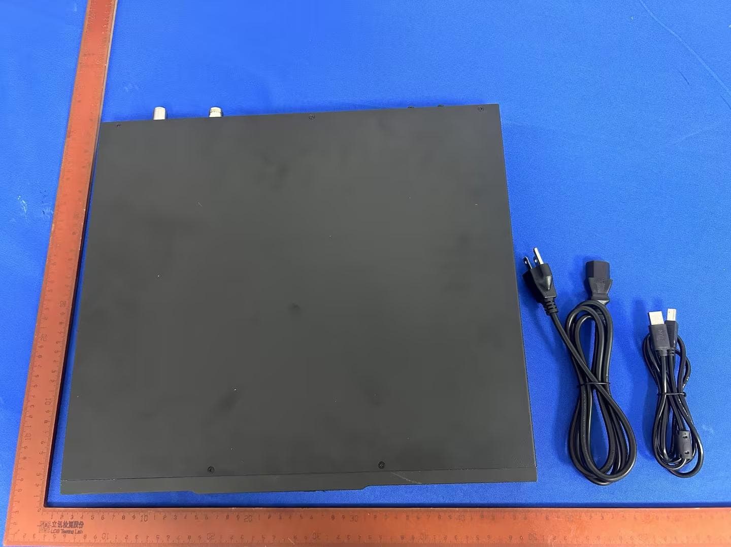
TEY-AR8000
Sep 03, 2024DMR Digital Repeater
Equipment Class
TNB - Licensed Non-Broadcast Station Transmitter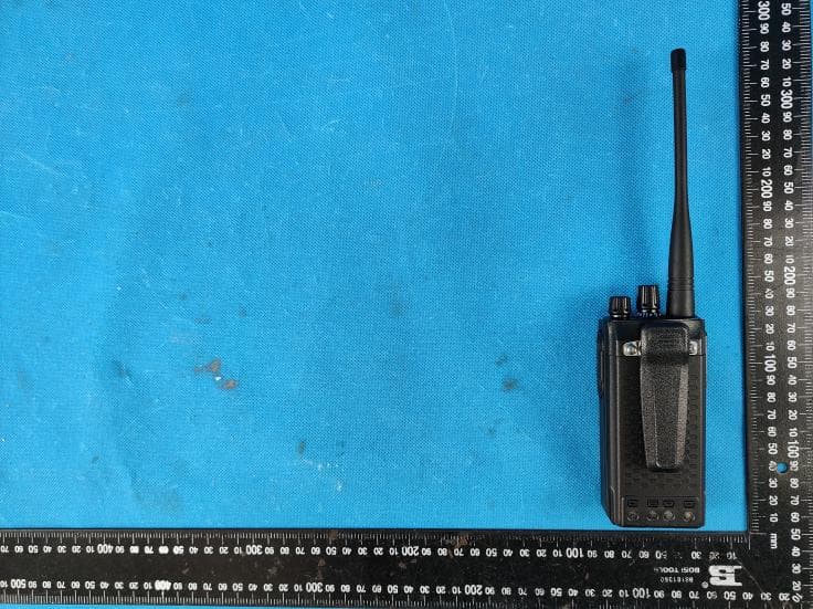
TEY-A580T
Jul 31, 2022Two Way Radio
Equipment Class
CXX - Communications Rcvr for use w/ licensed Tx and CBsTEY-A520T
Jul 27, 2022Two Way Radio
Equipment Class
CXX - Communications Rcvr for use w/ licensed Tx and CBs