TGD12200Furnace Mounted Transmitter
ENERNET Corporation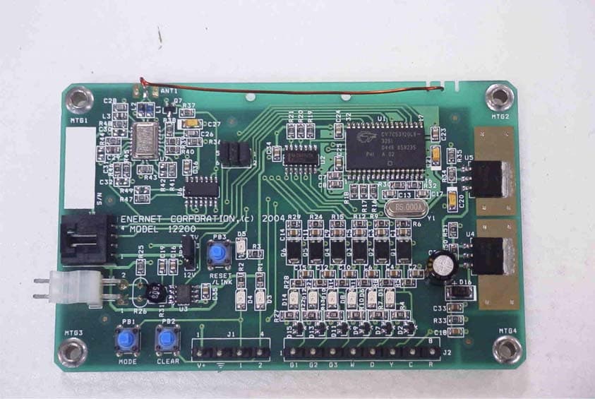
Click to zoom
Application Details
- Equipment Class
- DXX - Part 15 Low Power Communication Device Transmitter
- Date of Grant
- Nov 15, 2005
- Application Purpose
- Original Equipment
- Date of Application
- Nov 15, 2005
- Equipment Note
- Furnace Mounted Transmitter
- Frequency Range
- 915.85000000 - 916.85000000
- Company
- ENERNET Corporation
- Country
- United States
Documents & Files
Document Text
Text extracted from the exhibit documents filed with the FCC. Open a document above to read the original.
Cover Letter(s)
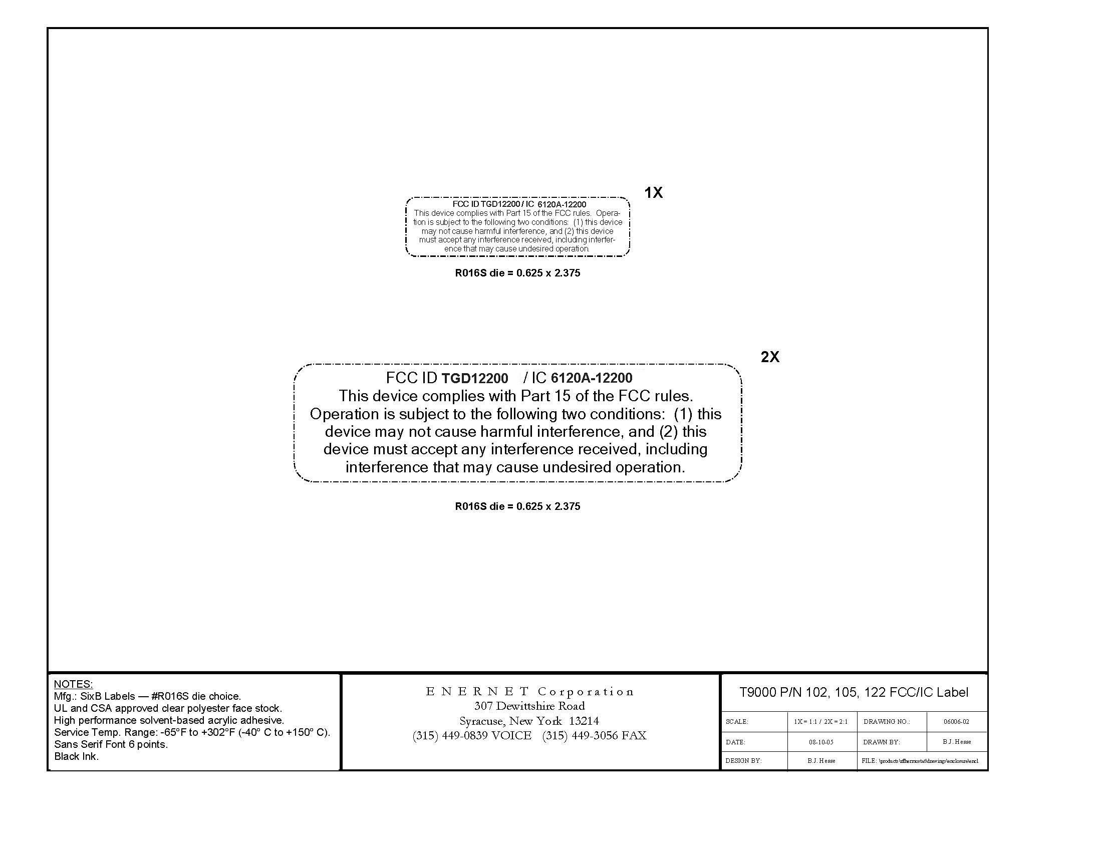
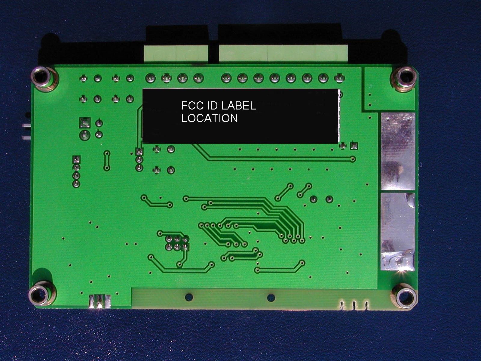
TIMCO ENGINEERING INC. 849 NW State Road 45 Newberry, Florida 32669 http://www.timcoengr.com 888.472.2424 F 352.472.2030 email: [email protected] APPLICANT: ENERNET CORPORATION FCC ID: TGD12200 REPORT #: E\ENERNET\1543AUT5\1543AUT5TestReport.doc Page 1 of 12 MODULAR REQUIREMENTS 1. The modular transmitter must have its own RF shielding. All of the transceiver RF portions are in a hermetically sealed case on the top surface of the module. 2. The modular transmitter must have buffered modulation data inputs. The transmitter has a modulated buffer amplifier for data transmission. See the operational description exhibit. 3. The modular transmitter must have its own power supply regulation. The schematic for this unit shows on-board regulators. 4. The modular transmitter must comply with the antenna requirements of Section 15.203 and 15.204(c). The module is being certified with four antennas Antenna Factor P/N 916-PW-QW – Chassis-mount monopole. Enernet P/N 060-012 - 1 Meter Coaxial monopole- PCB Mount Enernet P/N 060-011 – Wire monopole - PCB Mount Enernet P/N 060-010 – Helically loaded wire monopole, PCB mount All units are OEM professionally installed. 5. The modular transmitter must be tested in a stand-alone configuration. The 10200 was tested stand alone with each antenna. See the test setup photographs. 6. The modular transmitter must be labeled with its own FCC ID number. The FCC ID Label Sample and Label Location are included in the exhibits. TIMCO ENGINEERING INC. 849 NW State Road 45 Newberry, Florida 32669 http://www.timcoengr.com 888.472.2424 F 352.472.2030 email: [email protected] APPLICANT: ENERNET CORPORATION FCC ID: TGD12200 REPORT #: E\ENERNET\1543AUT5\1543AUT5TestReport.doc Page 2 of 12 MODULAR REQUIREMENTS CONTD. 7. The modular transmitter must comply with any specific rule or operating requirements applicable to the transmitter. The 10200 meets all of the requirements per FCC Rules Part 15.249 and data is included in the report. 8. The modular transmitter must comply with any applicable RF exposure requirements. The unit is of such low power it meets all RF Exposure requirements.
External Photos
ENERNET CORPORATION FCC ID: TGD12200 – with Antenna Factor P/No. 916-PW-QW, Chassis-Mount Monopole antenna FCC ID: TGD12200 – with Enernet P/No. 060-012 PCB mount, 1-Meter coaxial monopole antenna FCC ID: TGD12200 – with Enernet P/No. 060-011, PCB mount, wire monopole antenna FCC ID: TGD12200 – with Enernet P/No. 060-010, PCB Mount, Helically loaded wire monopole antenna
Internal Photos
ENERNET CORPORATION FCC ID: TGD12200 – with Antenna Factor P/No. 916-PW-QW, Chassis-Mount Monopole antenna FCC ID: TGD12200 – with Enernet P/No. 060-012 PCB mount, 1-Meter coaxial monopole antenna FCC ID: TGD12200 – with Enernet P/No. 060-011, PCB mount, wire monopole antenna FCC ID: TGD12200 – with Enernet P/No. 060-010, PCB Mount, Helically loaded wire monopole antenna
Operational Description
Circuit Descriptions ENERNET Corporation Confidential The RF transceiver in ENERNET products is based on RF Monolithics P/N TR1000, which contains an amplitude modulated, SAW-based, fixed frequency transmitter, and a “sequenced” TRF receiver (see their documentation for circuit details). Support component selection was based on RFM reference designs and application note, ASH Transceiver Designer’s Guide. A single resistor controls power level; the remaining support components control baseband parameters like receive threshold levels, bandwidth and AGC. RF transceiver circuitry in ENERNET products is virtually identical (see figs. 1-3). Thermostat 10200 contains a power switch, Q2, to reduce quiescent battery consumption. This switch, controlled by microcontroller U3, turns communications processor U6 and RF transceiver U1 on and off. Conversely, Remote Control Node (RCN) products, 10300, 10500, 12200 are continuously powered from a line-based supply. Thermostat and RCNs both contain a communications processor, which formats data into a balanced differential Manchester-coded, 9.766 kb/s stream applied to the transceiver TXMOD pin through level adjust resistor. Receive data is translated to 5 volt logic levels for all products except the 12200, which operates entirely on 3.3 volts. The communications processor keys the transceiver chip with a PTT signal. In the 10200 Thermostat, data processing and user interface is performed by a dedicated microcontroller U3, which contains crystal controlled oscillators on 5.0 MHz and 32 kHz. It supplies 5 MHz clock signal to communications processor U6 through clock switch Q3. In all of the RCN products, the communications processor itself runs data processing and user interface algorithms, and has its own 5.0 MHz crystal oscillator. Differences between the RCN products is power supply type and application I/O capacity. The 10300 Plug Load RCN is a self-contained, single channel line voltage switch with a NEMA standard power plug and receptacle. The 10500 Line Voltage J_BOX RCN is a single channel, 110-240 volt product with 0.5 A pilot duty solid state switch output. The 12200 PTAC/FC-24 RCN is a 6 channel, 24 VAC control.
Test Report
TIMCO ENGINEERING INC. 849 NW State Road 45 Newberry, Florida 32669 http://www.timcoengr.com 888.472.2424 F 352.472.2030 email: [email protected] APPLICANT: ENERNET CORPORATION FCC ID: TGD12200 REPORT #: E\ENERNET\1543AUT5\1543AUT5TestReport.doc COVER SHEET Test Report Product Name: FURNACE MOUNTED TRANSMITTER FCC ID: TGD12200 Applicant: ENERNET CORPORATION 307 DEWITTSHIRE ROAD SYRACUSE, NY 13214 Date Receipt: 7/21/2005 Date Tested: 8/18/05 TIMCO ENGINEERING INC. 849 NW State Road 45 Newberry, Florida 32669 http://www.timcoengr.com 888.472.2424 F 352.472.2030 email: [email protected] APPLICANT: ENERNET CORPORATION FCC ID: TGD12200 REPORT #: E\ENERNET\1543AUT5\1543AUT5TestReport.doc TABLE OF CONTENTS APPLICANT: ENERNET CORPORATION FCC ID: TGD12200 TABLE OF CONTENTS TEST REPORT CONTAINING: PAGE 1-2.........MODULAR REQUIREMENTS PAGE 3...........TEST EQUIPMENT LIST PAGE 4...........TEST PROCEDURE PAGE 5-7.........RADIATION INTERFERENCE TEST DATA PAGE 8-9.........OCCUPIED BANDWIDTH PAGE 10..........POWERLINE CONDUCTED PAGE 11-12.......POWERLINE CONDUCTED PLOTS EXHIBIT INCLUDED: REQUEST FOR CONFIDENTIALITY LETTER BLOCK DIAGRAM SCHEMATIC USERS MANUAL LABEL SAMPLE LABEL LOCATION EXTERNAL PHOTOGRAPHS INTERNAL PHOTOGRAPHS OPERATIONAL DESCRIPTION TEST SET UP PHOTOGRPAHS TIMCO ENGINEERING INC. 849 NW State Road 45 Newberry, Florida 32669 http://www.timcoengr.com 888.472.2424 F 352.472.2030 email: [email protected] APPLICANT: ENERNET CORPORATION FCC ID: TGD12200 REPORT #: E\ENERNET\1543AUT5\1543AUT5TestReport.doc Page 1 of 12 MODULAR REQUIREMENTS 1. The modular transmitter must have its own RF shielding. All of the transceiver RF portions are in a hermetically sealed case on the top surface of the module. 2. The modular transmitter must have buffered modulation data inputs. The transmitter has a modulated buffer amplifier for data transmission. See the operational description exhibit. 3. The modular transmitter must have its own power supply regulation. The schematic for this unit shows on-board regulators. 4. The modular transmitter must comply with the antenna requirements of Section 15.203 and 15.204(c). The module is being certified with four antennas Antenna Factor P/N 916-PW-QW – Chassis-mount monopole. Enernet P/N 060-012 - 1 Meter Coaxial monopole- PCB Mount Enernet P/N 060-011 – Wire monopole - PCB Mount Enernet P/N 060-010 – Helically loaded wire monopole, PCB mount All units are OEM professionally installed. 5. The modular transmitter must be tested in a stand-alone configuration. The 10200 was tested stand alone with each antenna. See the test setup photographs. 6. The modular transmitter must be labeled with its own FCC ID number. The FCC ID Label Sample and Label Location are included in the exhibits. TIMCO ENGINEERING INC. 849 NW State Road 45 Newberry, Florida 32669 http://www.timcoengr.com 888.472.2424 F 352.472.2030 email: [email protected] APPLICANT: ENERNET CORPORATION FCC ID: TGD12200 REPORT #: E\ENERNET\1543AUT5\1543AUT5TestReport.doc Page 2 of 12 MODULAR REQUIREMENTS CONTD. 7. The modular transmitter must comply with any specific rule or operating requirements applicable to the transmitter. The 10200 meets all of the requirements per FCC Rules Part 15.249 and data is included in the report. 8. The modular transmitter must comply with any applicable RF exposure requirements. The unit is of such low power it meets all RF Exposure requirements. TIMCO ENGINEERING INC. 849 NW State Road 45 Newberry, Florida 32669 http://www.timcoengr.com 888.472.2424 F 352.472.2030 email: [email protected] APPLICANT: ENERNET CORPORATION FCC ID: TGD12200 REPORT #: E\ENERNET\1543AUT5\1543AUT5TestReport.doc Page 3 of 12 EMC Equipment List Device Manufacturer Model Serial Number Cal/Char Date Due Date 3/10-Meter OATS TEI N/A N/A Listed 3/27/04 3/26/07 3-Meter OATS TEI N/A N/A Listed 1/13/03 1/12/06 Biconnical Antenna Eaton 94455-1 1057 CAL 3/18/03 3/18/05 Biconnical Antenna Eaton 94455-1 1096 CAL 8/17/04 8/17/06 Biconnical Antenna Electro- Metrics BIA-25 1171 CAL 4/29/05 4/29/07 Blue Tower Quasi-Peak Adapter HP 85650A 2811A01279 CAL 4/13/05 4/13/07 Blue Tower RF Preselector HP 85685A 2926A00983 CAL 8/3/05 8/3/07 Blue Tower Spectrum Analyzer HP 8568B 2928A04729 2848A18049 CAL 4/13/05 4/13/07 LISN Electro- Metrics ANS-25/2 2604 CAL 8/27/04 8/27/06 LISN Electro- Metrics EM-7820 2682 CAL 4/28/05 4/28/07 Log- Periodic Antenna Eaton 96005 1243 CAL 5/8/03 5/8/05 TIMCO ENGINEERING INC. 849 NW State Road 45 Newberry, Florida 32669 http://www.timcoengr.com 888.472.2424 F 352.472.2030 email: [email protected] APPLICANT: ENERNET CORPORATION FCC ID: TGD12200 REPORT #: E\ENERNET\1543AUT5\1543AUT5TestReport.doc Page 4 of 12 TEST PROCEDURE GENERAL: This report shall NOT be reproduced except in full without the written approval of TIMCO ENGINEERING, INC. The UUT was transmitting a test signal during the testing. RADIATION INTERFERENCE: The test procedure used was ANSI STANDARD C63.4-2003 using a HEWLETT PACKARD spectrum analyzer with a pre-selector. The analyzer was calibrated in dB above a microvolt at the output of the antenna. The resolution bandwidth was 100KHz and the video bandwidth was 300KHz up to 1.0GHz and 1.0MHz with a video BW of 3.0MHz above 1.0GHz. The ambient temperature of the UUT was 74.3oF with a humidity of 69%. FORMULA OF CONVERSION FACTORS: The Field Strength at 3m was established by adding the meter reading of the spectrum analyzer (which is set to read in units of dBuV) to the antenna correction factor supplied by the antenna manufacturer. The antenna correction factors are stated in terms of dB. The gain of the Preselector was accounted for in the Spectrum Analyzer Meter Reading. Example: Freq (MHz) METER READING + ACF = FS 33 20 dBuV + 10.36 dB = 30.36 dBuV/m @ 3m POWER LINE CONDUCTED INTERFERENCE: The procedure used was ANSI STANDARD C63.4- 2003 using a 50uH LISN. Both lines were observed. The bandwidth of the spectrum analyzer was 10kHz with an appropriate sweep speed. The ambient temperature …
Text truncated - open the document above for the full version.
Test Setup Photos
ENERNET CORPORATION FCC ID: TGD12200 TEST SET UP PHOTOS RADIATED TEST SET UP WITH ANTENNA FACTOR P./N 916-PW-QW, CHASSIS-MOUNT MONOPOLE RADIATED EMISSIONS TEST DATA WITH ENERNET P/NO. 060-012 PCB MOUNT, 1 METER COAXIAL MONOPOLE RADIATED EMISSIONS WITH ENERNET P/NO. 060-011, PCB MOUNT, WIRE MONOPOLE RADIATED EMISSIONS WITH ENERNET P/NO. 060-010, PCB MOUNT, HELICALLY LOADED WIRE MONOPOLE POWERLINE CONDUCTED EMISSIONS TEST SET UP
Contact Information
Applicant
Gary Carner(Senior Engineer)
Test Firm
Timco Engineering, Inc.S Sanders
Technical Specifications
| # | Rule Parts | Frequency Range | Power Output |
|---|---|---|---|
| 1 | 15C | 915.85 MHz - 916.85 MHz | - |
Other Applications from ENERNET Corporation
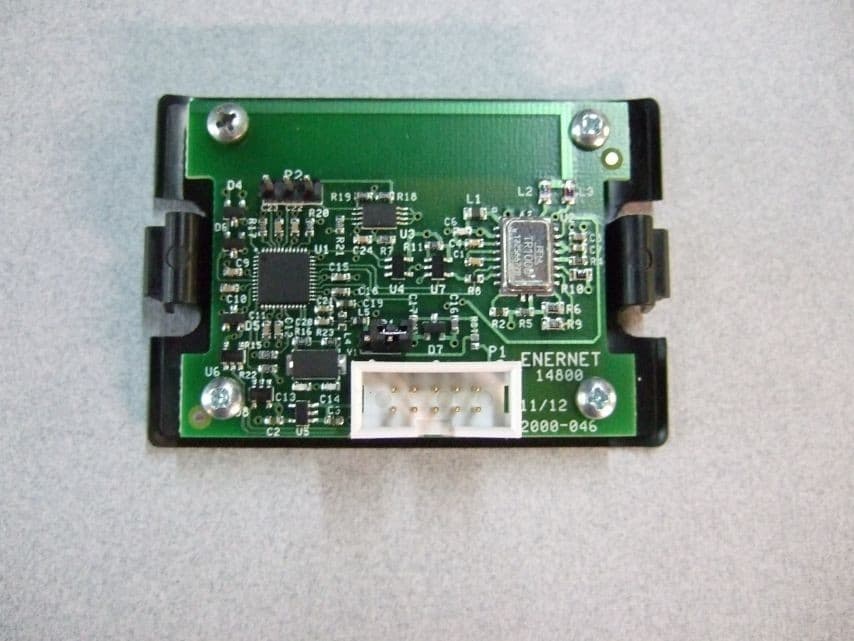
TGD14800
Feb 27, 2013WIRELESS THERMOSTAT ACCESSORY
Equipment Class
DXT - Part 15 Low Power Transceiver, Rx VerifiedTGD10300
Sep 19, 2005PLUG LOAD REMOTE CONTROL NODE
Equipment Class
DXX - Part 15 Low Power Communication Device TransmitterTGD10500
Sep 19, 2005LINE VOLTAGE J BOX RCN
Equipment Class
DXX - Part 15 Low Power Communication Device Transmitter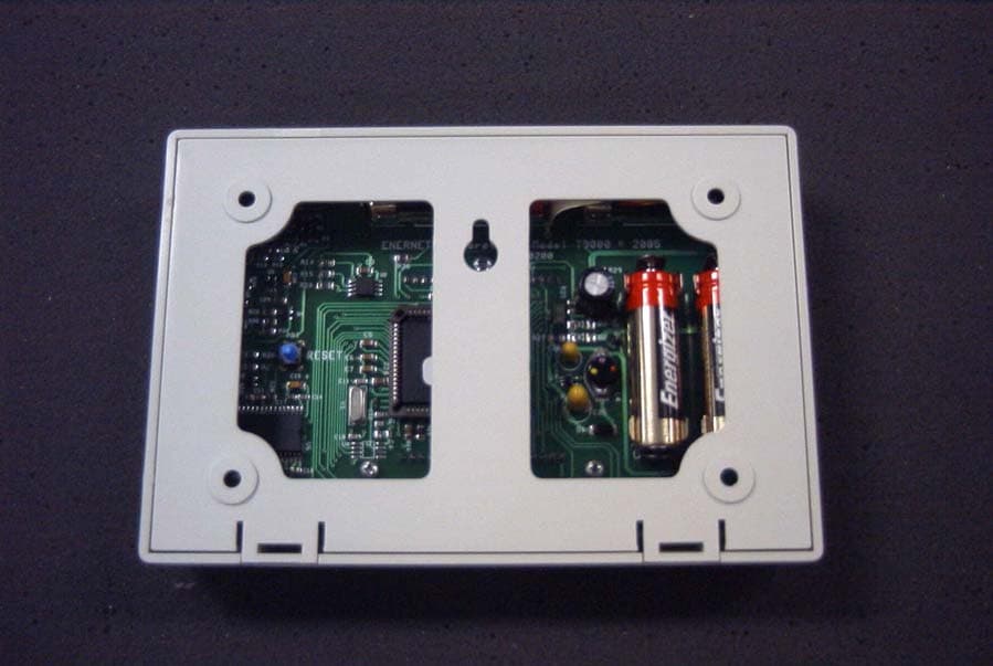
TGD10200
Sep 15, 2005WIRELESS THERMOSTAT
Equipment Class
DXX - Part 15 Low Power Communication Device Transmitter