TGTPJCKM1TProjack M1 Transmitter Board
Mov-A-Load Corporation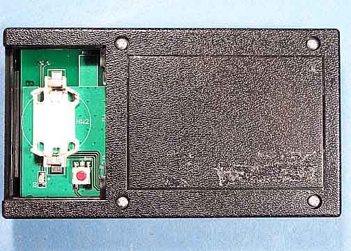
Click to zoom
Application Details
- Equipment Class
- DXT - Part 15 Low Power Transceiver, Rx Verified
- Date of Grant
- Jul 05, 2006
- Application Purpose
- Original Equipment
- Date of Application
- Jul 05, 2006
- Equipment Note
- Projack M1 Transmitter Board
- Frequency Range
- 902.27000000 - 927.67000000
- Company
- Mov-A-Load Corporation
- Country
- United States
Documents & Files
Document Text
Text extracted from the exhibit documents filed with the FCC. Open a document above to read the original.
Users Manual
1 REVISION 06-26-2006 PROJACK M1 Mov-A-Load Corporation www.movaload.com 1-866-668-3257 Owner’s Manual (Draft Copy) IMPORTANT: Read this manual before using this unit. Retain this manual for future reference. Carefully follow all instructions in this manual. Failure to follow all instructions in this manual will reduce the safety and performance of the unit. This manual contains important information on Safety, Training and Operation of the PROJACK M1 unit. IMPORTANT: Keep all PROJACKM1 literature with the unit for quick reference. Diagram OM1 (Picture of Complete Unit) Trailer Mobility by Remote Control Model # PROJACK M1 Small to Medium Gross Weight Trailers (GWT not to exceed 8,000 pounds and tongue weight not to exceed 800 pounds) Recreational, Utility, Commercial, Horse, and Specialty Bumper Pull Trailers 2 www.movaload.com THANK YOU Thank you for purchasing a Movaload product. The Owner’s Manual provides you with basic operating instructions and very important safety reminders. Please read the entire manual before installation or operating the unit. The knowledge, skill and training from reading the Owner’s manual is important in keeping the product in top operational condition and operating the unit safely. PRODUCT REFERENCES, ILLUSTRATIONS AND SPECIFICATIONS. All information, illustrations, and specifications in this manual are based on the latest product information available at the time of printing. Movaload reserves the right to change or improve the design of any Movaload Product at any time without notice and without obligation to modify products previously manufactured. Copyright©2005 Movaload Corporation. All Rights Reserved. This product is covered by one or more U.S. Patents. Other Patents pending. SERVICE INFORMATION Service on the Movaload unit within the warranty period should be performed only by an authorized and approved service dealer or certified Movaload Installation representative. In order to obtain a list of service dealers, please call 1-866-668-3257 For more details about your unit, visit our website at www.movaload.com DO NOT RETURN THE UNIT TO THE SELLER WITHOUT PROOF OF PURCHASE. Please make note of the following information before having your product installed. Serial Number _______________________ Model Number _______________________ TABLE OF CONTENTS 1 - 2 INTRODUCTION 3 WARRANTY INFORMATION 4 FCC & ICES CERTIFICATION INFORMATION 5 - 6 SAFETY 7 SAFETY LABELS 8 - 11 PREPARATION & TRAINING 12 – 13 OPERATION 3 MOVALOAD CORPORATION LIMITED ONE-YEAR WARRANTY For one (1) year from the date of original purchase, when this MOVALOAD CORPORATION product is properly maintained and operated according to the Owner’s Manual, MOVALOAD CORPORATION will repair, free of charge, any defect in material or workmanship. If this product is used for commercial or rental purposes, this limited warranty applies for ninety (90) days from the date of original purchase. This warranty does not apply in the following cases: • Items which become worn during normal use, such as Tires. Normal Wear Parts are warranted to be free from defect in material and workmanship as delivered with the product. Any claim for repair or replacement of Normal Wear Parts must be made within thirty (90) days of the date of purchase. • Repair necessary because of operator abuse, tampering with or altering the product or negligence, including bent shafts or steering devices and the failure to maintain the equipment according to the instructions contained in the Owner’s Manual. • Minor mechanical adjustments which are not due to any defect in material or workmanship. For assistance in making such adjustments, consult your Maintenance manual. WARRANTY SERVICE IS AVAILABLE BY RETURNING THE PRODUCT TO THE NEAREST CERTIFIED MOVALOAD SERVICE CENTER. To make a claim under this MOVALOAD CORPORATION one (1) year Limited Warranty, return the unit along with your proof of purchase to an Authorized Service Center near you. To locate the nearest Authorized Service Center, call MOVALOAD CORPORATION directly at 1-800-866-3257 or visit us online (refer to contact information below). This Limited Warranty is made in lieu of all other warranties, expressed or implied. Seller’s and manufacturer’s only obligation under this Limited Warranty shall be to repair or replace such parts and components of the product proved to be defective in accordance with published Warranty Policy. Neither Seller or manufacturer shall be liable for any injury, loss, or damage direct, indirect or consequential arising out of the use of or inability to use the product. Before using, the owner shall determine the stability of the product and it’s suitable for the intended use and user assumes all risk and liability in connection therewith. Except as provided herein, MOVALOAD CORPORATION makes no express warranties or any implied warranties of merchantability or fitness for a particular purpose and all warranties of any type is limited to the duration of the written limited warranty set forth herein. There will be charges rendered for repairs to the product made after the expiration of the aforesaid one year Warranty Period. All statements, technical information and recommendations contained herein are based on tests we believe to be reliable, but the accuracy or completeness thereof is not guaranteed. This warranty gives you specific legal rights, and you may also have other rights which may vary from state of state. This Limited Warranty contains the complete text of the warranty and may not be modified either orally or in writing. If you have questions or require assistance please contact Movaload Customer Service Department. MOVALOAD CORPORATION Customer Service Department 2245 Industrial Drive Dyersburg, TN 38024 866-668-3257 www.movaload.com 4 FCC STATEMENT Model # M1 RECEIVER FCC ID: TGTPJCKM1R Model # M1 TRANSMITTER FCC ID: TGTPJCKM1T This device complies with part 15 of the FCC rules. Operation is subject to the following two conditions: (1…
Text truncated - open the document above for the full version.
Users Manual
1 PROJACK M1 SERVICE AND REPAIR (Draft Copy) TABLE OF CONTENTS SECTION PAGE • Notes, Cautions, and Warnings 2 • Transmitter, Receiver, On & Off Pushbuttons, LEDs, & Wiring Harness Theory of Operation 3 • Transmitter/Receiver Troubleshooting 5 • Battery 7 • Fuse 9 • On & Off Pushbutton Switch Assembly Replacement 9 • LED PCB Assembly Replacement 11 • Receiver PCB/Wiring Harness Replacement 13 • Synchronizing Transmitter and Receiver 17 • Synchronizing Transmitter Keypad With Transmitter PCB 19 • Tire/Wheel Assembly Replacement 19 • Drive Chain Replacement 20 • Chain Sprocket Replacement 22 • Lower Drive Gearmotor Replacement 22 • Lift Gearmotor Replacement 24 • Inner Tube Assembly Replacement 25 • Lift Screw Thrust Bearing Replacement 28 • Steering Housing Assembly Replacement 28 • Drive Axle Replacement 28 • Lower Frame Subassembly Replacement 30 • ProJack M1 Exploded View 32 • Parts List For Projack M1 33 2 Fig. 1.0 NOTES, CAUTIONS, AND WARNINGS NOTE: There are several references in this manual to the left and/or the right side of the unit. To determine the left or right side, stand beside the unit and face the same direction as the trailer tongue is pointing. CAUTION: There are many torque specifications given in this manual for the various bolts and screws found on the unit. Some of these torque specs are given in “in. lb.” ratings while others are given in “ft. lb.” ratings. Be sure to read the specs carefully before tightening a bolt or screw. CAUTION: Do not at any time let brake fluids, gasoline, petroleum-based products, penetrating oils, and etc. contact plastic parts. They contain chemicals that can damage, weaken or destroy plastic. CAUTION: The PROJACK M1 unit contains delicate electronic components that can be damaged by static shock. Always work in a static free area and wear a grounded anti-static wrist strap when handling any electronic component. WARNING: When servicing, use only identical PROJACK M1 replacement parts. Use of any other part may create a hazard or cause product damage. WARNING: When servicing the PROJACK M1 unit, always disconnect the negative battery cable to prevent accidental starting. WARNING: Some repair procedures require the PROJACK M1 unit to be unbolted from its mounting brackets and placed onto a suitable workbench. The unit weighs approximately 120 lbs without a battery installed. Use of an overhead chain hoist or winch is recommended, if available. Do not lift the unit without help. Proper lifting technique is essential to avoid injury. Lift with your arms and legs, not your back. Ignoring these precautions can result in back injury. 3 TRANSMITTER, RECEIVER, ON & OFF PUSHBUTTONS, LEDs, & WIRING HARNESS THEORY OF OPERATION Fig. 1.1 The PROJACK M1 unit is controlled by a remotely operated handheld transmitter. The transmitter has eight (8) pushbuttons and one (1) LED. There are six (6) pushbuttons that control the three (3) gearmotors on the main unit. There is a pushbutton that controls the illumination LEDs and there is a pushbutton that will turn off the power on the main unit. The LED on the face of the transmitter should illuminate green when any button is pressed. This indicates that a signal is being sent to the receiver in the main unit. A readily available CR2450 coin battery, located beneath the battery cover, powers the transmitter. Fig. 1.2 When any button on the transmitter is pressed, an electronic signal is sent to a receiver inside the unit. The receiver interprets the signal and then commands the appropriate relays/switches to open or close. These relays/switches control current to the three (3) gearmotors and illumination LEDs. The receiver, relays/switches, and other related electronic components are mounted on a printed circuit board (PCB). This receiver PCB is located under the PCB cover at the top of the unit. There are two pushbuttons mounted on the front of the PCB cover (one with a black protective cover and one with a red cover). The pushbutton with the black cover is used to turn ON the receiver. The pushbutton with the red cover is used to turn OFF the receiver. These pushbuttons are wired to the receiver PCB with a detachable connector. The receiver PCB has an automatic time delayed OFF feature. If the receiver doesn’t detect a signal from the transmitter for 1½ minutes, the unit will automatically turn itself OFF. There are seven (7) LEDs located of the front of the PCB cover. The six (6) upper LEDs combine to form an illumination light and are controlled by the LIGHTS pushbutton on the transmitter. The seventh LED, located just above the ON & OFF pushbuttons, is an operating condition indicator. This LED should illuminate green after the ON pushbutton has been pressed. Whenever the receiver is detecting a signal from the transmitter, the operating condition LED should flash green. If a problem (such as an overload on the lift motor) is detected by the electronic components on the receiver PCB, the operating condition LED should illuminate red. All seven (7) LEDs are mounted to a PCB. The LED PCB is wired to the receiver PCB with a detachable connector. 4 The receiver PCB is designed to go into a safety mode whenever the lift gearmotor is put into a stall condition, such as when the lift screw is at either of its limits. When in this safety mode, the operating condition LED will illuminate red and the function associated with the overload will cease to operate. To exit the safety mode, press the transmitter button that controls the opposite function (press DOWN if the lift screw has hit the UP limit or vise versa). In some cases, the lift screw may be jammed against a limit to an extent that the gearmotor cannot provide enough power to reverse the screw and back it off the limit. An access plug is provided in the top of the PCB cover so that a 9/16-inch socket wrench can be used to turn the lift screw and back it off the limit. The PROJACK M1 unit utilizes three (3) gearmotors. One gearmotor is located near the top …
Text truncated - open the document above for the full version.
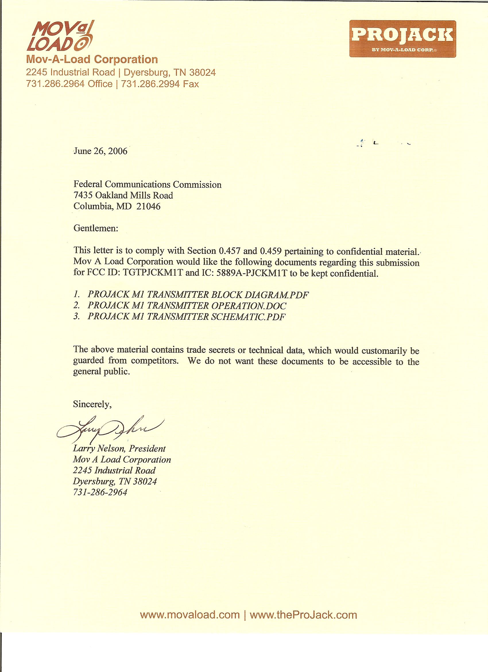
Cover Letter(s)
Response to E06-000177-1 IC 1. A revised label has been uploaded. 2. A revised Canadian form has been uploaded with the RF exposure statement signed.
External Photos
Transmitter Full View Top Transmitter Full View Bottom Front Back Left Right
ID Label/Location Info
S H EE T S C A L E S I Z E F S C M NO . D W G NO . R E V D A T E D E S CR I P T I ON R E V R E V I S I ON S A PPR O V E D T I T L E M ov - A - L o a d C o r p . 2245 I n d u s t r i a l R d . D y e r s b u r g , T N 38024 L A B EL F O R T R A N S M I TTE R C A 1 O F 1 F CC I D : T G T P J C K M 1 T T h i s d e v i ce c o m p li e s w i t h P a r t 15 o f t h e F CC R u l e s : O p e r a t i on i s s u b j ec t t o t h e f o ll o w i ng t w o c on d i t i on s : ( 1 ) T h i s d e v i ce m a y no t ca u s e h a r m f u l i n t e r f e r e n ce a n d ( 2 ) t h i s d e v i ce m u s t acce p t a ny i n t e r f e r e n ce r ece i v e d , i n c l u d i ng i n t e r f e r e n ce t h a t m a y ca u s e un d e s i r e d o p e r a t i on . I C : 5889 A - P J C K M 1 T M OD EL : P R O J A C K M 1 T R A N S M I TTE R T h i s C l a ss B d i g i t a l a pp a r a t u s m ee t s a ll r e qu i r e m e n t s o f t h e C a n a d i a n I n t e r f e r e n ce - C a u s i ng E qu i p m e n t R e gu l a t i on s M ov a l o a d C o r p o r a t i on M ov a l o a d . c o m 2 . 00 1 . 2 1
ID Label/Location Info
S H EE T S C A L E S I Z E F S C M NO . D W G NO . R E V D A T E D E S CR I P T I ON R E V R E V I S I ON S A PPR O V E D T I T L E M ov - A - L o a d C o r p . 2245 I n d u s t r i a l R d . D y e r s b u r g , T N 38024 T R A N S M I TTE R W I T H L A B EL S C A 1 O F 1 0 . 1 25 0 . 1 25 0 . 1 25 0 . 1 25 S E R I A L # 0 . 5 00 0 . 5 00 F CC I D : T G T P J C K M 1 T T h i s d e v i ce c o m p li e s w i t h P a r t 15 o f t h e F CC R u l e s : O p e r a t i on i s s u b j ec t t o t h e f o ll o w i ng t w o c on d i t i on s : ( 1 ) T h i s d e v i ce m a y no t ca u s e h a r m f u l i n t e r f e r e n ce a n d ( 2 ) t h i s d e v i ce m u s t acce p t a ny i n t e r f e r e n ce r ece i v e d , i n c l u d i ng i n t e r f e r e n ce t h a t m a y ca u s e un d e s i r e d o p e r a t i on . I C : 5889 A - P J C K M 1 T M OD EL : P R O J A C K M 1 T R A N S M I TTE R T h i s C l a ss B d i g i t a l a pp a r a t u s m ee t s a ll r e qu i r e m e n t s o f t h e C a n a d i a n I n t e r f e r e n ce - C a u s i ng E qu i p m e n t R e gu l a t i on s M ov a l o a d C o r p o r a t i on M ov a l o a d . c o m
Internal Photos
Transmitter Board Top Transmitter Board Bottom
Test Report
Page 1 of 34 Report No.: FC06-037 MOV-A-LOAD CORP. TEST REPORT FOR THE HAND-HELD REMOTE CONTROL, PROJACK M1 TRANSMITTER BOARD FCC PART 15 SUBPART C SECTIONS 15.209 & 15.249, SUBPART B SECTION 15.109 CLASS B AND RSS-210 COMPLIANCE DATE OF ISSUE: JUNE 19, 2006 PREPARED FOR: Mov-A-Load Corp. 2245 Industrial Road Dyersburg, TN 38024 PREPARED BY: Mary Ellen Clayton CKC Laboratories, Inc. 5046 Sierra Pines Drive Mariposa, CA 95338 W.O. No.: 84961Date of test: June 5-14, 2006 Report No.: FC06-037 This report contains a total of 34 pages and may be reproduced in full only. Partial reproduction may only be done with the written consent of CKC Laboratories, Inc. The results in this report apply only to the items tested, as identified herein. Page 2 of 34 Report No.: FC06-037 TABLE OF CONTENTS Administrative Information .............................................................................................3 FCC to Canada Standard Correlation Matrix...................................................................4 Conditions for Compliance ..............................................................................................4 Approvals .........................................................................................................................4 FCC 15.31(e) Voltage Variation......................................................................................5 FCC 15.31(m) Number Of Channels ...............................................................................5 FCC 15.33(a) Frequency Ranges Tested .........................................................................5 FCC 15.35 Analyzer Bandwidth Settings ........................................................................5 FCC 15.203 Antenna Requirements ................................................................................5 EUT Operating Frequency ...............................................................................................5 Temperature And Humidity During Testing....................................................................5 Equipment Under Test (EUT) Description ......................................................................6 Equipment Under Test .....................................................................................................6 Peripheral Devices ...........................................................................................................6 Report of Measurements ..................................................................................................7 Table 1: FCC 15.109 Highest Radiated Emission Levels: 30-1000 MHz ...........7 Table 2: FCC 15.109 Highest Radiated Emission Levels: 1-5 GHz....................8 Table 3: FCC 15.209 Six Highest Radiated Emission Levels: 3-30 MHz...........9 Table 4: FCC 15.209 Six Highest Radiated Emission Levels: 30-1000 MHz.....10 Table 5: FCC 15.209 Six Highest Radiated Emission Levels: 1-10 GHz ...........11 Table 6: FCC 15.249 Fundamental Emission Levels ..........................................12 20dB Bandwidth ..................................................................................................13 Band Edge ............................................................................................................16 EUT Setup........................................................................................................................18 Correction Factors............................................................................................................18 Table A: Sample Calculations .............................................................................18 Test Instrumentation and Analyzer Settings ....................................................................19 Spectrum Analyzer Detector Functions ...............................................................19 Peak..........................................................................................................19 Quasi-Peak ...............................................................................................19 Average ....................................................................................................19 EUT Testing.....................................................................................................................20 Radiated Emissions ..............................................................................................20 Appendix A: Test Setup Photographs..............................................................................21 Photograph Showing Transmitter Transmitting...................................................22 Photograph Showing Transmitter Transmitting...................................................23 Photograph Showing Transmitter Receiving .......................................................24 Photograph Showing Transmitter Receiving .......................................................25 Appendix B: Test Equipment List ...................................................................................26 Appendix C: Measurement Data Sheets ..........................................................................27 Page 3 of 34 Report No.: FC06-037 ADMINISTRATIVE INFORMATION DATE OF TEST: June 5-14, 2006 DATE OF RECEIPT: June 5, 2006 MANUFACTURER: Mov-A-Load Corp. 2245 Industrial Road Dyersburg, TN 38024 REPRESENTATIVE: Sandy Hutcherson TEST LOCATION: CKC Laboratories, Inc. 1120 Fulton Place Fremont, CA 94539 TEST METHOD: ANSI C63.4 (2003), RSS-210 and RSS GEN PURPOSE OF TEST: To demonstrate the compliance of the Hand-Held Remote Control, ProJack M1 Transmitter Board with the requirements for FCC Part 15 Subpart C Sections 15.209 & 15.249 and Subpart B Section 15.109 Class B and RSS-210 devices. Page 4 of 34 Report No.: FC06-037 FCC TO CANADA STANDARD CORRELATION MATRIX Canadian Standard Canadian Section FCC StandardFCC SectionTest Description RSS 2106.2.147CFR15.209General Radiated Emissions Require…
Text truncated - open the document above for the full version.
Test Setup Photos
PHOTOGRAPH SHOWING TRANSMITTER TRANSMITTING { tc "Photograph Showing Transmitter Transmitting "\l 2 } Front View PHOTOGRAPH SHOWING TRANSMITTER TRANSMITTING { tc "Photograph Showing Transmitter Transmitting "\l 2 } Back View PHOTOGRAPH SHOWING TRANSMITTER RECEIVING { tc "Photograph Showing Transmitter Receiving "\l 2 } Front View PHOTOGRAPH SHOWING TRANSMITTER RECEIVING { tc "Photograph Showing Transmitter Receiving "\l 2 } Back View
Contact Information
Applicant
Sandy Hutcherson(Office Manager)
Technical Contact
CKC Laboratories, Inc.Mary Ellen Clayton
[email protected]800-500-4362
5046 Sierra Pines Drive · Mariposa, California · United States
Test Firm
CKC Laboratories, Inc.Steve Behm
Technical Specifications
| # | Rule Parts | Frequency Range | Power Output |
|---|---|---|---|
| 1 | 15C | 902.27 MHz - 927.67 MHz | - |
Other Applications from Mov-A-Load Corporation
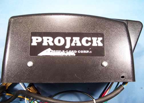
TGTPJCKM1R
Jul 05, 2006Projack M1 Receiver Board
Equipment Class
DXT - Part 15 Low Power Transceiver, Rx Verified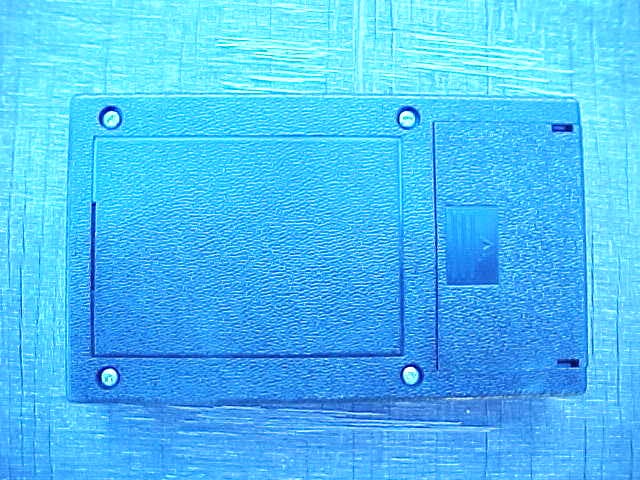
TGTPROJACKM1
Aug 22, 2005Transmitter
Equipment Class
DSC - Part 15 Security/Remote Control Transmitter