TGTPROJACKM1Transmitter
Mov-A-Load Corporation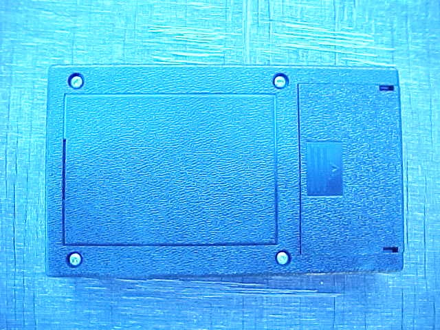
Click to zoom
Application Details
- Equipment Class
- DSC - Part 15 Security/Remote Control Transmitter
- Date of Grant
- Aug 22, 2005
- Application Purpose
- Original Equipment
- Date of Application
- Aug 22, 2005
- Equipment Note
- Transmitter
- Frequency Range
- 418.00000000 - 418.00000000
- Company
- Mov-A-Load Corporation
- Country
- United States
Documents & Files
Document Text
Text extracted from the exhibit documents filed with the FCC. Open a document above to read the original.
Users Manual
1 REVISION 6-29-05 PROJACK M1 Mov-A-Load Corporation www.movaload.com 1-866-668-3257 Owner’s Manual IMPORTANT: Read this manual before using this unit. Retain this manual for future reference. Carefully follow all instructions in this manual. Failure to follow all instructions in this manual will reduce the safety and performance of the unit. This manual contains important information on Safety, Training and Operation of the PROJACK M1 unit. Diagram OM1 (Picture of Complete Unit) Trailer Mobility by Remote Control Model # PROJACK M1 Small to Medium Gross Weight Trailers (GWT not to exceed 8,000 pounds and tongue weight not to exceed 800 pounds) Recreational, Utility, Commercial, Horse, and Specialty Bumper Pull Trailers 2 [email protected] THANK YOU Thank you for purchasing a Movaload product. The Owner’s Manual provides you with basic operating instructions and very important safety reminders. Please read the entire manual before installation or operating the unit. The knowledge, skill and training from reading the Owner’s manual is important in keeping the product in top operational condition and operating the unit safely. PRODUCT REFERENCES, ILLUSTRATIONS AND SPECIFICATIONS. All information, illustrations, and specifications in this manual are based on the latest product information available at the time of printing. Movaload reserves the right to changes or improve the design of any Movaload Product at any time without notice and without obligation to modify products previously manufactured. Copyright©2005 Movaload Corporation. All Rights Reserved. This product is covered by one or more U.S. Patents. Other Patents pending. SERVICE INFORMATION Service on the Movaload unit within the warranty period should be performed only by an authorized and approved service dealer or certified Movaload Installation representative. In order to obtain a list of service dealers, please call 1-866-668-3257 For more details about your unit, visit our website at www.movaload.com DO NOT RETURN THE UNIT TO THE SELLER WITHOUT PROOF OF PURCHASE. Please make note of the following information before having your product installed. Serial Number _______________________ Model Number _______________________ UPC _______________________ TABLE OF CONTENTS 1 - 2 INTRODUCTION 3 WARRANTY INFORMATION 4 FCC & ICES CERTIFICATION INFORMATION 5 - 6 SAFETY 7 SAFETY LABELS 8 - 11 PREPARATION & TRAINING 12 – 13 OPERATION 3 MOVALOAD CORPORATION LIMITED ONE-YEAR WARRANTY For one (1) year from the date of original purchase, when this MOVALOAD CORPORATION product is properly maintained and operated according to the Owner’s Manual, MOVALOAD CORPORATION will repair, free of charge, any defect in material or workmanship. If this product is used for commercial or rental purposes, this limited warranty applies for ninety (90) days from the date of original purchase. This warranty does not apply in the following cases: • Items which become worn during normal use, such as Remote Control Transmitter, Chains and Tires. Normal Wear Parts are warranted to be free from defect in material and workmanship as delivered with the product. Any claim for repair or replacement of Normal Wear Parts must be made within thirty (30) days of the date of purchase. • Repair necessary because of operator abuse, tampering with or altering the product or negligence, including bent shafts or steering devices and the failure to maintain the equipment according to the instructions contained in the Owner’s Manual. • Minor mechanical adjustments which are not due to any defect in material or workmanship. For assistance in making such adjustments, consult your Maintenance manual. WARRANTY SERVICE IS AVAILABLE BY RETURNING THE PRODUCT TO THE NEAREST CERTIFIED MOVALOAD SERVICE CENTER. To make a claim under this MOVALAD CORPORATION one (1) year Limited Warranty, return the unit along with your proof of purchase to an Authorized Service Center near you. To locate the nearest Authorized Service Center, call MOVALOAD CORPORATION directly at 1-800-866-3257 visit us online (refer to contact information below). This Limited Warranty is made in lieu of all other warranties, expressed or implied. Seller’s and manufacturer’s only obligation under this Limited Warranty shall be to repair or replace such parts and components of the product proved to be defective in accordance with published Warranty Policy. Neither Seller or manufacturer shall be liable for any injury, loss, or damage direct, indirect or consequential arising out of the use of or inability to use the product. Before using, the owner shall determine the stability of the product and it’s suitable for the intended use and user assumes all risk and liability in connection therewith. Except as provided herein, MOVALOAD CORPORATION makes no express warranties or any implied warranties of merchantability or fitness for a particular purpose and all warranties of any type is limited to the duration of the written limited warranty set forth herein. There will be charges rendered for repairs to the product made after the expiration of the aforesaid one year Warranty Period. All statements, technical information and recommendations contained herein are based on tests we believe to be reliable, but the accuracy or completeness thereof is not guaranteed. This warranty gives you specific legal rights, and you may also have other rights which may vary from state of state. This Limited Warranty contains the complete text of the warranty and may not be modified either orally or in writing. If you have questions or require assistance please contact Movaload Customer Service Department. MOVALOAD CORPORATION Customer Service Department 2245 Industrial Drive Dyersburg, TN 38024 866-668-3257 www.movaload.com 4 FCC STATEMENT Model # PROJACK M1 FCC ID # TGTPROJACKM1 This device complies with part 15 of the FCC rules. Operation is subject to the following two conditions: (1) This device may not cause harmful interference and (2) Thi…
Text truncated - open the document above for the full version.
Cover Letter(s)
Scott McCutchan From: Mike [[email protected]] Sent: Friday, May 20, 2005 3:42 PM To: Scott McCutchan Subject: FW: Response to Inquiry to FCC (Tracking Number 165903) 8/11/2005 Here is the Duty Cycle question I asked the FCC. Best Regards, Mike Christensen Lab Manager Compatible Electronics, Inc. - Brea Division Phone: 714-579-0500 Fax: 714-579-1850 www.celectronics.com -----Original Message----- From: Generic Office of Engineering Technology [mailto:[email protected]] Sent: Friday, May 20, 2005 1:39 PM To: [email protected] Subject: Response to Inquiry to FCC (Tracking Number 165903) Inquiry: I have a customer who has a device that uses pulse modulation on a 433 MHz 15.231 device. I know that for testing we need to have the device in its worst case duty cycle to use the appropriate duty cycle correction factor. However, the particular encoder being used in this device has the capability of using more than 16 million different addresses, all of them random. I have talked to the manufacturer of the encoder and have been told that the duty cycle will range between approximately 40 and 45 percent which calculates to about a 1 dB swing. Is there a FCC policy on what to do in this case? Is it permitted to provide plots of the duty cycle that we get and use the correction factor of 45 percent, even though the duty cycle may appear to be 43 percent? Thank you for your help. Best Regards Mike Christensen Lab Manager Compatible Electronics, Inc. - Brea Division Phone: 714-579-0500 Fax: 714-579-1850 www.celectronics.com Response: A customer who has a device that uses pulse modulation on a 433 MHz 15.231 device. I know that for testin g we need to have the device in its worst case duty cycle to use the appropriate duty cycle correction factor. However, the particular encoder being used in this device has the capability of using more than 16 million different addresses, all of them random. I have talked to the manufacturer of the encoder and have been told that the duty cycle will range between approximately 40 and 45 percent which calculates to about a 1 dB swing. Please use the worse case duty cycle of 45 percent. You may show a plot of 40 percent duty cycle with this explanation. Do not reply to this message. Please select the Reply to an Inquiry Response link from the OET Inquiry S ystem to add any additional information pertaining to this inquiry. 8/11/2005
Cover Letter(s)
Mr. Fujimoto: In order for processing of this application (FCC ID: TGTPROJACK1) to continue, the following issue(s) will have to be addressed: 1) A confidentiality letter was requested in the application form but was not included in the uploaded items. Please confirm whether confidentiality is still wanted and if so, please provide a letter. 2) Please provide a block diagram of the transmitter. Based on the schematics and photos, the block diagram appears to be for the receiver and not the transmitter. The item(s) indicated above must be submitted before processing can continue on the above referenced application. Failure to provide the requested information within 60 days of the original e-mail date may result in application dismissal and forfeiture of the filing fee. Also, please note that partial responses increase processing time and should not be submitted. Please upload responses and/or exhibits to the electronic filing website. Your correspondence number is TGTPROJACKM1-1. Best regards, Scott McCutchan Operations Manager Compatible Electronics TCB 19121 El Toro Road Silverado, California 92676 (949) 589-0700 fax (949) 589-7700 [email protected] Correspondence by Project Project Number: -975535646 Correspondence Number Memo TGTPROJACKM1-1 1) A confidentiality letter was requested in the application form but was not included in the uploaded items. Please confirm whether confidentiality is still wanted and if so, please provide a letter. Response: The confidentiality letter has been uploaded to the exhibits. 2) Please provide a block diagram of the transmitter. Based on the schematics and photos, the block diagram appears to be for the receiver and not the transmitter. Response: The block dia gram for the transmitter has been uploaded. This is the same block diagram that was used to get the Canadian approval.
Test Report
Report Number: B50708D1 FCC Part 15 Subpart B and FCC Section 15.231 Test Report Transmitter Model: Projack M1 114 OLINDA DRIVE, BREA, CALIFORNIA 92823 PHONE: (714) 579-0500 FAX: (714) 579-1850 Page 1 of 16 FCC PART 15, SUBPART B and C TEST REPORT for TRANSMITTER MODEL: PROJACK M1 Prepared for MOV-A-LOAD CORPORATION 2245 INDUSTRIAL ROAD DYERSBURG, TENNESSEE 38024 Prepared by:_____________________ KYLE FUJIMOTO Approved by:____________________ MICHAEL CHRISTENSEN COMPATIBLE ELECTRONICS INC. 114 OLINDA DRIVE BREA, CALIFORNIA 92823 (714) 579-0500 DATE: JULY 19, 2005 REPORT APPENDICES TOTAL BODY A B C D E PAGES 16 2 2 2 12 12 46 This report shall not be reproduced except in full, without the written approval of Compatible Electronics. Report Number: B50708D1 FCC Part 15 Subpart B and FCC Section 15.231 Test Report Transmitter Model: Projack M1 114 OLINDA DRIVE, BREA, CALIFORNIA 92823 PHONE: (714) 579-0500 FAX: (714) 579-1850 Page 2 of 16 TABLE OF CONTENTS Section / Title PAGE GENERAL REPORT SUMMARY 4 SUMMARY OF TEST RESULTS 4 1. PURPOSE 5 2. ADMINISTRATIVE DATA 6 2.1 Location of Testing 6 2.2 Traceability Statement 6 2.3 Cognizant Personnel 6 2.4 Date Test Sample was Received 6 2.5 Disposition of the Test Sample 6 2.6 Abbreviations and Acronyms 6 3. APPLICABLE DOCUMENTS 7 4. DESCRIPTION OF TEST CONFIGURATION 8 4.1 Description of Test Configuration - EMI 8 4.1.1 Cable Construction and Termination 9 5. LISTS OF EUT, ACCESSORIES AND TEST EQUIPMENT 10 5.1 EUT and Accessory List 10 5.2 EMI Test Equipment 11 6. TEST SITE DESCRIPTION 12 6.1 Test Facility Description 12 6.2 EUT Mounting, Bonding and Grounding 12 7. TEST PROCEDURES 13 7.1 Radiated Emissions (Spurious and Harmonics) Test 13 7.2 Radiated Emissions (Spurious and Harmonics) Test (continued) 14 7.3 Bandwidth of the Fundamental 15 8. CONCLUSIONS 16 Report Number: B50708D1 FCC Part 15 Subpart B and FCC Section 15.231 Test Report Transmitter Model: Projack M1 114 OLINDA DRIVE, BREA, CALIFORNIA 92823 PHONE: (714) 579-0500 FAX: (714) 579-1850 Page 3 of 16 LIST OF APPENDICES APPENDIX TITLE A Laboratory Recognitions B Modifications to the EUT C Additional Models Covered Under This Report D Diagrams, Charts, and Photos • Test Setup Diagrams • Radiated Emissions Photos • Antenna and Effective Gain Factors E Data Sheets LIST OF FIGURES FIGURE TITLE 1 Plot Map And Layout of Radiated Test Site Report Number: B50708D1 FCC Part 15 Subpart B and FCC Section 15.231 Test Report Transmitter Model: Projack M1 114 OLINDA DRIVE, BREA, CALIFORNIA 92823 PHONE: (714) 579-0500 FAX: (714) 579-1850 Page 4 of 16 GENERAL REPORT SUMMARY This electromagnetic emission test report is generated by Compatible Electronics Inc., which is an independent testing and consulting firm. The test report is based on testing performed by Compatible Electronics personnel according to the measurement procedures described in the test specifications given below and in the "Test Procedures" section of this report. The measurement data and conclusions appearing herein relate only to the sample tested and this report may not be reproduced without the written permission of Compatible Electronics, unless done so in full. This report must not be used to claim product endorsement by NVLAP, NIST or any other agency of the U.S. Government. Device Tested: Transmitter Model: Projack M1 S/N: N/A Product Description: See Expository Statement. Modifications: The EUT was not modified during the testing. Manufacturer: Mov-A-Load Corporation 2245 Industrial Road Dyersburg, Tennessee 38024 Test Dates: July 5 and 8, 2005 Test Specifications : EMI requirements CFR Title 47, Part 15 Subpart B; and Subpart C, Sections 15.205, 15.209, and 15.231 Test Procedure: ANSI C63.4: 2003 Test Deviations: The test procedure was not deviated from during the testing. SUMMARY OF TEST RESULTS TEST DESCRIPTION RESULTS 1 Conducted RF Emissions, 150 kHz - 30 MHz This test was not performed because the EUT operates on batteries only and cannot be plugged into the AC public mains. 2 Radiated RF Emissions, 9 kHz - 4400 MHz Complies with the Class B limits of CFR Title 47, Part 15, Subpart B; and Subpart C, sections 15.205, 15.209, and 15.231. 3 -20 dB Bandwidth of the Fundamental Complies with the limits of Subpart C, sections 15.231 [c]. Report Number: B50708D1 FCC Part 15 Subpart B and FCC Section 15.231 Test Report Transmitter Model: Projack M1 114 OLINDA DRIVE, BREA, CALIFORNIA 92823 PHONE: (714) 579-0500 FAX: (714) 579-1850 Page 5 of 16 1. PURPOSE This document is a qualification test report based on the Electromagnetic Interference (EMI) tests performed on the Transmitter Model: Projack M1. The EMI measurements were performed according to the measurement procedure described in ANSI C63.4: 2003. The tests were performed in order to determine whether the electromagnetic emissions from the equipment under test, referred to as EUT hereafter, are within the Class B specification limits defined by CFR Title 47, Part 15, Subpart B; and Subpart C, sections 15.205, 15.209, and 15.231. Report Number: B50708D1 FCC Part 15 Subpart B and FCC Section 15.231 Test Report Transmitter Model: Projack M1 114 OLINDA DRIVE, BREA, CALIFORNIA 92823 PHONE: (714) 579-0500 FAX: (714) 579-1850 Page 6 of 16 2. ADMINISTRATIVE DATA 2.1 Location of Testing The EMI tests described herein were performed at the test facility of Compatible Electronics, 114 Olinda Drive, Brea, California 92823. 2.2 Traceability Statement The calibration certificates of all test equipment used during the test are on file at the location of the test. The calibration is traceable to the National Institute of Standards and Technology (NIST). 2.3 Cognizant Personnel Mov-A-Load Corporation Sandy Hutcherson Office Manager Larry D. Nelson President Compatible Electronics, Inc. Kyle Fujimoto Test Engineer Benigno Chavez Test Engineer Michael Christensen Lab Manager 2.4 Date Test Sample was Received The test sample was received prior to its qualification testing on July 5, 2005. 2.5 Disp…
Text truncated - open the document above for the full version.
Test Report
MS Series Encoder Data Structure The MS Series encoder is designed to securely register button presses or switch closures over a wireless link for remote contro l applications. It will turn eight parallel input lines into a secure, encoded serial bit stream output. The MS Series algorithm is designed to create a data stream with a 50% duty cycle by using the same number of high bits and low bits. Two wait times reduce this duty cycle to just below 50%. Power Up Is the SEND Line High? Send Data Logic State Description: 1 = HIGH 0 = LOW Total bits, including start and stop bits = 80 Total 1’s = 40 Total 0’s = 40 Value for each bit per baud rate: 2400bps = 417uS or 1.18% of duty cycle 9600bps = 104uS or 1.01% of duty cycle 19200bps = 52uS or 0.85% of duty cycle 28800bps = 35uS or 0.74% of duty cycle 680uS 465uS 800uS 0 01101000 1 0 10101010 1 0 01010101 1 0 00000000 1 0 11111111 1 0 11101010 1 00000000 1010 Wait Time Processing Time Wait Time Wake Noise Filter Error Check ADDR-H ADDR-M ADDR-L Data Byte Error Check 11111111 Duty Cycle = Time High Total Time 40 bits + 800uS 80 bits + 680uS + 465uS + 800uS (40* 417 uS) + 800uS (80* 417 uS) + 1 ,945uS 17,480 uS 35,305 uS = 4 9.51% == MS Series Encoder Data Structure The MS Series encoder is designed to securely register button presses or switch closures over a wireless link for remote contro l applications. It will turn eight parallel input lines into a secure, encoded serial bit stream output. The MS Series algorithm is designed to create a data stream with a 50% duty cycle by using the same number of high bits and low bits. Two wait times reduce this duty cycle to just below 50%. Power Up Is the SEND Line High? Send Data Logic State Description: 1 = HIGH 0 = LOW Total bits, including start and stop bits = 80 Total 1’s = 40 Total 0’s = 40 Value for each bit per baud rate: 2400bps = 417uS or 1.18% of duty cycle 9600bps = 104uS or 1.01% of duty cycle 19200bps = 52uS or 0.85% of duty cycle 28800bps = 35uS or 0.74% of duty cycle 680uS 465uS 800uS 0 01101000 1 0 10101010 1 0 01010 101 1 0 000 00000 1 0 1 0 0 0 1 0 00 1 0 11101010 1 00000000 1010 Wait Time Processing Time Wait Time Wake Noise Filter Error Check ADDR-H ADDR-M ADDR-L Data Byte Error Check 11111111 Duty Cycle = Time High Total Time 40 bits + 800uS 80 bits + 680uS + 465uS + 800uS ( 3 4 * 417 uS) + 800uS (80* 417 uS) + 1 ,945uS 14,978 uS 35,305 uS = 42.42% ==
Test Report
Ref Lvl 92 dB V Ref Lvl 92 dB V RBW 1 MHz VBW 1 MHz A Unit dB V P20 RF Att 20 dB IN1 SWT 100 ms Center 418 MHz10 ms/ 1VIEW1AP 0 10 20 30 40 50 60 70 80 -8 92 11 Delta 1 [T1] -0.03 dB 36.272545 ms D1 54 dB V T2 T1 Date: 8.JUL.2005 11:07:18 Plot showing the pulse train repeats about each 36 seconds. NOTE: Please see the screenshot of the oscilloscope for the exact time of one pulse train.
Contact Information
Applicant
Sandy Hutcherson(Office Manager)
Technical Contact
Compatible ElectronicsKyle Fujimoto
[email protected]714-579-0500
114 Olinda Drive · Brea, California · United States
Test Firm
Compatible Electronics, Inc.Michael Christensen
Technical Specifications
| # | Rule Parts | Frequency Range | Power Output |
|---|---|---|---|
| 1 | 15.231 | 418 MHz - 418 MHz | - |
Other Applications from Mov-A-Load Corporation
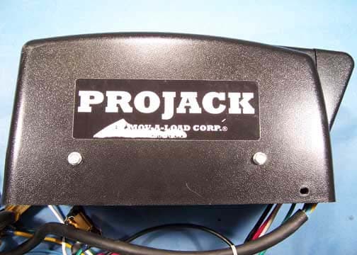
TGTPJCKM1R
Jul 05, 2006Projack M1 Receiver Board
Equipment Class
DXT - Part 15 Low Power Transceiver, Rx Verified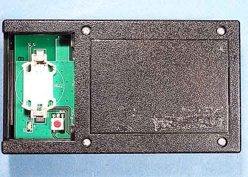
TGTPJCKM1T
Jul 05, 2006Projack M1 Transmitter Board
Equipment Class
DXT - Part 15 Low Power Transceiver, Rx Verified