TGZBT001Bluetooth Module
Able Systems Limited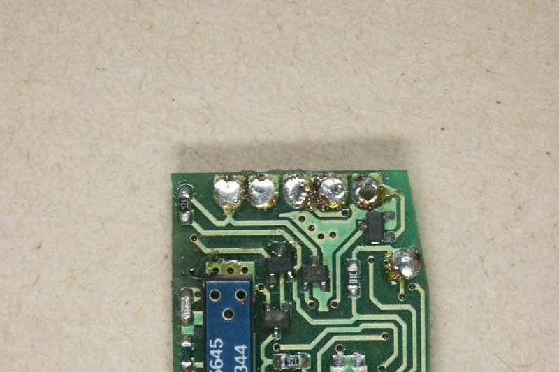
Click to zoom
Application Details
- Equipment Class
- DSS - Part 15 Spread Spectrum Transmitter
- Date of Grant
- Jan 25, 2006
- Application Purpose
- Original Equipment
- Date of Application
- Jan 25, 2006
- Equipment Note
- Bluetooth Module
- Frequency Range
- 2402.00000000 - 2480.00000000
- Company
- Able Systems Limited
- Country
- United Kingdom
Documents & Files
Document Text
Text extracted from the exhibit documents filed with the FCC. Open a document above to read the original.
Users Manual
1.06/Nov 2004BlueRS+BD Manual BlueRS+BD Bluetooth Serial Adapter Firmware User Manual Version 1.06 Date Nov 2004 © Stollmann Entwicklungs- und Vertriebs-GmbH BlueRS+BD Manual1.06/Nov 2004 Exclusion of Liability The present manual by Stollmann Entwicklungs- und Vertriebs-GmbH (hereinafter referred to as Stollmann) reflects the present state of the art of the products described therein. We have endeavored to give a description that is as complete and clear as possible in order to make work with our products as easy as possible for you. All the same, the manual may contain technical inaccuracies and typing errors. As a result of the rapid advance in the art, we must also reserve the right to incorporate technical alterations and developments without separate advance notice. That is why Stollmann does not give any warranty for the contents of the manual and for its continuing applicability. Nor is Stollmann liable for any loss of information or any incorrect use of information that might result from consultation of the manual. Particularly, Stollmann is not liable for damage, nor indirect damage (including damage caused by financial loss, delays affecting business transactions or interruptions of business and similar consequences), arising from the use or improper use of this manual, not even in the case where it was pointed out to Stollmann or an agent of Stollmann that such damage might be sustained. This does not, of course, affect our legal liability for damages based on any intent or gross negligence. With respect to the data given in this manual, Stollmann does not warrant the non- existence of industrial property rights (trademarks, patents, utility models, etc.). Nor are trade names, brand names, company names and product names in general use but are subject to the relevant trademark, patent, utility model and registered design rights. The information must neither in whole nor even in part be copied, translated, reproduced or in any other way transferred to or stored on any electronic medium or other machine. The purchase and use of software are governed by the General Conditions of Delivery and Payment as well as the Terms of License of Stollmann. If any of the provisions is a registered liability or on use are or become ineffective for statutory reasons, this will not affect the other provisions. Trademark of Stollmann Entwicklungs- und Vertriebs-GmbH. 1.06/Nov 2004BlueRS+BD Manual Table of contents 1Introduction ..................................................................................................... 4 1.1 Product description ......................................................................................... 4 2Operation Modes of BlueRS+BD Software ..................................................... 4 3Using BlueRS+BD Software ........................................................................... 5 3.1 Automatic connection establishment............................................................... 6 3.2 AT command set for BlueRS+BD ................................................................... 7 3.2.1 Bluetooth specific AT commands ........................................................... 14 3.2.2 AT command S register set .................................................................... 19 3.2.3 AT result codes ...................................................................................... 19 3.3 Table for coding Bluetooth services .............................................................. 20 4BlueRS+BD Configurator command set....................................................... 21 4.1 Configuring BlueRS+BD after power on........................................................ 21 4.2 Configuring BlueRS+BD with AT commands................................................ 22 4.3 Remote configuration using the BlueRS+BD Configurator commands ......... 22 4.4 List of BlueRS+BD Configurator commands ................................................. 23 5Diagnostic and error messages ....................................................................39 5.1 Error messages from AT command set........................................................ 39 5.2 Bluetooth error codes.................................................................................... 39 6Regulatory Information.................................................................................. 42 6.1 Copyright and Trademark Notices ................................................................ 42 7History........................................................................................................... 43 BlueRS+BD Manual1.06/Nov 2004 1 Introduction We are very pleased to see that you have bought a Stollmann product and would like to express our appreciation. This documentation is valid for BlueRS+BD Bluetooth Serial Port Profile Software, version V1.1.025 or later. 1.1 Product description BlueRS+BD is a Bluetooth Serial Port Profile Software for use with Zeevo ZV 4002 and ZV 4301 chip and implements the following functions: • Connect devices with a serial port to any Bluetooth link. It gives access to other devices situated in the same Bluetooth area (piconet). • Data transmission with rates from 300 up to 230400 baud. • The connected serial device can drive BlueRS+BD software by using - asynchronous AT commands - automatic connection setup - accept incoming Bluetooth links. • Configuration of the BlueRS+BD software can be performed via the serial interface (local configuration) or via the Bluetooth link (remote configuration). The following profiles are supported: • One serial profile channel for transparent data communication via the Bluetooth link. • A second serial profile channel for management access from another Bluetooth device using a Bluetooth link. 2 Operation Modes of BlueRS+BD Software The BlueRS+BD software supports two different modes: • Running on a Bluetooth module with a Stollmann Bluetooth address enables full functionality. • Running on …
Text truncated - open the document above for the full version.
Cover Letter(s)
11.07.2005 Federal Communications Commission Authorization and Evaluation Division Equipment Authorization Branch 7435 Oakland Mills Road Columbia, MD 21046 To whom it may concern: We, the undersigned, hereby authorize Electronic Technology Systems Dr. Genz GmbH to act on our behalf in all matters relating to applications for equipment authorization AM-01, including the signing of all documents relating to these matters. Any and all acts carried out by Electronic Technology Systems Dr. Genz GmbH on our behalf shall have the same effect as acts of our own. We also hereby certify that no party to this application is subject to a denial of benefits, including FCC benefits, pursuant to Section 5301 of the Anti-Drug Abuse Act of 1988, 21 U.S.C. 862. Sincerely, Ian Evans Engineering Manager Able Systems Limited
Cover Letter(s)
06/07/05 Federal Communications Commission Equipment Authorization Branch 7435 Oakland Mills Road Columbia, MD 21046 Request for Confidentiality Able Systems Limited FCC ID: TGZBT001 FCC Part 15 Certification Gentlemen, In accordance with 0.459 of CFR 47, Able Systems Limited hereby requests confidentiality of all Block Diagrams, Circuit Description, Schematic Diagrams, PCB Layout Diagrams, Parts Lists and Operational Description attachments for the subject application. These documents contain detailed system and equipment description and related information about the product which Able Systems Limited considers to be proprietary, confidential and a custom design and otherwise would not release to the general public. Since the design is a basis from which future technological products will evolve, Able Systems Limited considers that this information would be of benefit to its competitors and that the disclosure of the information in these documents would give competitors an unfair advantage in the market. Sincerely, Ian Evans Engineering Manager Able Systems Limited
Cover Letter(s)
Page 1 of 3 11.07.2005 Electronic Technology Systems Dr. Genz GmbH Storkower Strasse 38c, D-15526 Reichenwalde B. Berlin To whom it may concern: We, the undersigned, declare that to the best of our knowledge the PAN1440 Bluetooth Module meets each of the criteria outlined in the FCC’s DA 00-1407 Modular Transmitter Approval. The criteria (in bold type) and justifications (in normal type) are outlined below. 1. The modular transmitter must have its own RF shielding. This is intended to ensure that the module does not have to rely upon the shielding provided by the device into which it is installed in order for all modular transmitter emissions to comply with Part 15 limits. It is also intended to prevent coupling between the RF circuitry of the module and any wires or circuits in the device into which the module is installed. Such coupling may result in non-compliant operation. The PAN1440 incorporates its own RF shielding. 2. The modular transmitter must have buffered modulation/data inputs (if such inputs are provided) to ensure that the module will comply with Part 15 requirements under conditions of excessive data rates or over-modulation. The PAN1440 is a type approved, microcontroller-based module. Ancillary equipment connected to the module does not exert control over modulation techniques nor the frequencies of operation. Digital communication with the module is within data rates defined in the specification of the PAN1440. 3. The modular transmitter must have its own power supply regulation. This is intended to ensure that the module will comply with Part 15 requirements regardless of the design of the power supplying circuitry in the device into which the module is installed. The PAN1440 Module incorporates a 3.3 volt linear regulator. Page 2 of 3 4. The modular transmitter must comply with the antenna requirements of Section 15.203 and 15.204(c). The antenna must either be permanently attached or employ a “unique” antenna coupler (at all connections between the module and the antenna, including the cable). Any antenna used with the module must be approved with the module, either at the time of initial authorization or through a Class II permissive change. The “professional installation” provision of Section 15.203 may not be applied to modules. The PAN1440 Module features a fixed, integral antenna and has no provision for connection of other antennas. 5. The modular transmitter must be tested in a stand-alone configuration, i.e., the module must not be inside another device during testing. This is intended to demonstrate that the module is capable of complying with Part 15 emission limits regardless of the device into which it is eventually installed. Unless the transmitter module will be battery powered, it must comply with the AC line conducted requirements found in Section 15.207. AC or DC power lines and data input/output lines connected to the module must not contain ferrites, unless they will be marketed with the module (see Section 15.27(a)). The length of these lines shall be length typical of actual use or, if that length is unknown, at least 10 centimeters to insure that there is no coupling between the case of the module and supporting equipment. Any accessories, peripherals, or support equipment connected to the module during testing shall be unmodified or commercially available (see Section 15.31(i)). The module provided for approval is in a stand-alone configuration: ancillary equipment has only been provided to facilitate testing (by incorporation of commercially available RS232 drivers for easy connection to a serial port). The unit is a low voltage, d.c. device, not intended for connection to a.c. supplies. Connection to the PAN1440 Module is via fixed length pins, and is intended to be surface mounted or accommodated by vias in the system’s printed circuit board. 6. The modular transmitter must be labeled with its own FCC ID number, and, if the FCC ID is not visible when the module is installed inside another device, then the outside of the device into which the module is installed must also display a label referring to the enclosed module. This exterior label can use wording such as the following: “Contains Transmitter Module FCC ID: XYZMODEL1” or “Contains FCC ID: XYZMODEL1.” Any similar wording that expresses the same meaning may be used. The Grantee may either provide such a label, an example of which must be included in the application for equipment authorization, or, must provide adequate instructions along with the module which explain this requirement. In the latter case, a copy of these instructions must be included in the application for equipment authorization. A label containing the text “FCC ID:”, the Grantee Code and the Equipment Product Page 3 of 3 Code “BT001” will be affixed centrally on the underside of the module (there is no room on the top side of the module to affix this label). The containing equipment will bear the marking “Contains FCC ID:”, followed by the Grantee and Equipment Product code of the module. 7. The modular transmitter must comply with any specific rule or operating requirements applicable to the transmitter and the manufacturer must provide adequate instructions along with the module to explain any such requirements. A copy of these instructions must be included in the application for equipment authorization. For example, there are very strict operational and timing requirements that must be met before a transmitter is authorized for operation under Section 15.231. For instance, data transmission is prohibited, except for operation under Section 15.231(e), in which case there are separate field strength level and timing requirements. Compliance with these requirements must be assured. The PAN1440 has passed the Bluetooth Qualification Program and therefore found to meet the operating and timing requirements therein. Transmission parameters are not under the control of the system into which the module is integrated. Over…
Text truncated - open the document above for the full version.
External Photos
ELECTRONIC TECHNOLOGY SYSTEMS DR.GENZ GMBH REGISTRATIONNUMBER: G0M20506-9614-C-1 ELECTRONIC TECHNOLOGY SYSTEMS DR. GENZ GMBH STORKOWER STR. 38C, D-15526 REICHENWALDE B. BERLIN Appendix Page 1 of 4 Appendix A. Pictures ELECTRONIC TECHNOLOGY SYSTEMS DR.GENZ GMBH REGISTRATIONNUMBER: G0M20506-9614-C-1 ELECTRONIC TECHNOLOGY SYSTEMS DR. GENZ GMBH STORKOWER STR. 38C, D-15526 REICHENWALDE B. BERLIN Appendix Page 2 of 4
ID Label/Location Info
ELECTRONIC TECHNOLOGY SYSTEMS DR.GENZ GMBH REGISTRATIONNUMBER: G0M20506-9614-C-1 ELECTRONIC TECHNOLOGY SYSTEMS DR. GENZ GMBH STORKOWER STR. 38C, D-15526 REICHENWALDE B. BERLIN Appendix Page 1 of 4 Appendix A. Pictures
Internal Photos
ELECTRONIC TECHNOLOGY SYSTEMS DR.GENZ GMBH REGISTRATIONNUMBER: G0M20506-9614-C-1 ELECTRONIC TECHNOLOGY SYSTEMS DR. GENZ GMBH STORKOWER STR. 38C, D-15526 REICHENWALDE B. BERLIN Appendix Page 1 of 4 Appendix A. Pictures ELECTRONIC TECHNOLOGY SYSTEMS DR.GENZ GMBH REGISTRATIONNUMBER: G0M20506-9614-C-1 ELECTRONIC TECHNOLOGY SYSTEMS DR. GENZ GMBH STORKOWER STR. 38C, D-15526 REICHENWALDE B. BERLIN Appendix Page 2 of 4
RF Exposure Info
___________________________________________________________________________________ ETS Handelsregister: Bankverbindung: Electronic Technology Systems Dr. Genz GmbH Amtsgericht Frankfurt/Oder HRB 5151 Sparkasse Oder-Spree Storkower Strasse 38c Geschäftsführung: Dr. Dietmar Genz BLZ 170 550 50 D-15526 Reichenwalde b. Berlin Norbert Kaspar Kto. Nr. 3105165974 ELECTRONIC TECHNOLOGY SYSTEMS DR.GENZ GMBH RF Exposure Calculation Applicant: Able Systems Ltd FCC ID: TGZBT001 The antenna shown in this filing must not be co-located or operated in conjunction with any other antenna or transmitter. End users may not be provided with the module installation instructions. OEM integrators and end users must be provided with transmitter operating conditions for satisfying RF exposure compliance.. For portable applications OEM integrators need no SAR evaluation. The max source-based time-averaged output of 1.6mW is below the low threshold of 24mW for d < 2.5 cm. integral Antenna requirement § 15.203). An intentional radiator shall be designed to ensure that no antenna other than that furnished by the responsible party shall be used with the device. The use of a permanently attached antenna or of an antenna that uses a unique coupling to the intentional radiator shall be considered sufficient to comply with the provisions of this section. The manufacturer may design the unit so that a broken antenna can be replaced by the user, but the use of a standard antenna jack or electrical connector is prohibited. The Following calculation is the reference data for 20, 2.5 and 1.5 cm distance.
Test Report
ELECTRONIC TECHNOLOGY SYSTEMS DR. GENZ GMBH TEST - REPORT FCC RULES PART 15 / SUBPART C FCC ID: TGZBT001 Test report no.: G0M20506-9614-C-1 Certificate 1983-01 ELECTRONIC TECHNOLOGY SYSTEMS STORKOWER STRASSE 38C, D-15526 REICHENWALDE B. BERLIN DR. GENZ GMBH PHONE +49-33631-888 00 FAX +49-33631-888 660 ETS Dr. Genz GmbH, Germany Registration number: G0M20506-9614-C-1 Page 1 of 34 ELECTRONIC TECHNOLOGY SYSTEMS DR.GENZ GMBH TABLE OF CONTENTS 1 General information 1.1 Notes 1.2 Testing laboratory 1.3 Details of approval holder 1.4 Application details 1.5 Test item 1.6 Test standards 2 Technical test 2.1 Summary of test results 2.2 Test environment 2.3 Test equipment utilized 2.4 General Test Procedure 3 Test Results 3.1 Peak output power 3.2 Equivalent isotropic radiated power 3.3 RF exposure radiated emission 3.4 Antenna requirement 3.5 Out of band radiated emission 3.6 Transmitter radiated emissions in restricted bands 3.7 Spurious emissions (tx) 3.8 Carrier frequency separation 3.9 Number of hopping frequency 3.10 Time of occupancy 3.11 20 dB bandwidth 3.12 Band-edge compliance of RF emissions 3.13 Conducted measurement at (AC) power line ETS Dr. Genz GmbH, Germany Registration number: G0M20506-9614-C-1 Page 2 of 34 ELECTRONIC TECHNOLOGY SYSTEMS DR.GENZ GMBH 1 General Information 1.1 Notes The purpose of conformity testing is to increase the probability of adherence to the essential requirements or conformity specifications, as appropriate. The complexity of the technical specifications, however, means that full and thorough testing is impractical for both technical and economic reasons. Furthermore, there is no guarantee that a test sample which has Passed all the relevant tests conforms to a specification. Neither is there any guarantee that such a test sample will interwork with other genuinely open systems. The existence of the tests nevertheless provides the confidence that the test sample possesses the qualities as maintained and that is performance generally conforms to representative cases of communications equipment. The test results of this test report relate exclusively to the item tested as specified in 1.5. The test report may only be reproduced or published in full. Reproduction or publication of extracts from the report requires the prior written approval of the ELECTRONIC TECHNOLOGY SYSTEMS DR. GENZ GMBH. Tester: 21.12.2005 D. Hoppe Date ETS-Lab. Name Signature Technical responsibility for area of testing: 21.12.2005 N. Kaspar Date ETS Name Signature ETS Dr. Genz GmbH, Germany Registration number: G0M20506-9614-C-1 Page 3 of 34 ELECTRONIC TECHNOLOGY SYSTEMS DR.GENZ GMBH 1.2 Testing laboratory 1.2.1 Location ELECTRONIC TECHNOLOGY SYSTEM DR. GENZ GMBH (ETS) Storkower Straße 38c D-15526 Reichenwalde b. Berlin Germany Telefon : +49 33631 888 00 Telefax : +49 33631 888 66 1.2.2 Details of accreditation status A CCREDITED TESTING LABORATORY DAR- REGISTRATION NUMBER: TTI-P-G 126/96 A CCREDITED COMPETENT BODY DAR- REGISTRATION NUMBER: BPT-ZE-026/96 FCC FILED TEST LABORATORY REG. NO. 96970 B LUETOOTH QUALIFICATION TEST FACILITY (BQTF) A CCREDITED BY BLUETOOTH QUALIFICATION REVIEW BOARD I NDUSTRY CANADA FILED TEST LABORATORY REG. NO. IC 3470 A2LA ACCREDITED Certificate Number 1983-01 1.3 Details of approval holder Name : ABLE Systems Limited Street : Denton Drive, Northwich Town : Cheshire, CW9 7TU Country : United Kingdom Telephone : +44 1606 48621 Fax : +44 1606 44903 Contact : Mr. Stephen J. Pardoe E-mail : [email protected] ETS Dr. Genz GmbH, Germany Registration number: G0M20506-9614-C-1 Page 4 of 34 ELECTRONIC TECHNOLOGY SYSTEMS DR.GENZ GMBH 1.4 Application details Date of receipt of application : 07.06.2005 Date of receipt of test item : 07.06.2005 Date of test : 07.06.2005 – 04.07.2005 1.5 Test item Description of test item : PAN1440 Bluetooth Module Type identification : PAN1440 Serial number : without Photos : See Appendix A Technical data Frequency band : 2402 – 2480 MHz Frequency (ch A) : 2402 MHz Frequency (ch B) : 2441 MHz Frequency (ch C) : 2480 MHz Transmitter Vnom Vnom –15 % Vnom +15 % Power (ch A) : Conducted: 1.18 dBm Conducted: 1.09 dBm Conducted: 1.10 dBm Power (ch B) : Conducted: 0.32 dBm Conducted: 0.22 dBm Conducted: 0.39 dBm Power (ch C) : Conducted: -1.20 dBm Conducted: -1.18 dBm Conducted: -1.09 dBm Power supply : 5.0 V DC 120 V AC (AC/DC Adapter) Operating mode : duplex Type of modulation : FHSS Antenna type : Print antenna Antenna gain : 2 dBi ETS Dr. Genz GmbH, Germany Registration number: G0M20506-9614-C-1 Page 5 of 34 ELECTRONIC TECHNOLOGY SYSTEMS DR.GENZ GMBH Host device : none Classification : Fixed Device Mobile Device (Human Body distance > 20cm) Portable Device (Human Body distance < 20cm) Manufacturer: (if applicable) Name : ABLE Systems Limited Street : Denton Drive, Northwich Town : Cheshire, CW9 7TU Country : United Kingdom Additional information: The test sample is designed as Bluetooth device. Its pseudorandom hopping scheme, authentication, receiver parameters, synchronization procedure and other parameters are determined by Bluetooth Core Specification. According to attached declaration of manufacturer this device don’t work in master inquiry mode. So we have only one frequency hopping system and the hopping sequence of the master inquiry mode is not very fied. ETS Dr. Genz GmbH, Germany Registration number: G0M20506-9614-C-1 Page 6 of 34 ELECTRONIC TECHNOLOGY SYSTEMS DR.GENZ GMBH 1.6 Test standards Technical standard : FCC RULES PART 15 / SUBPART C § 15.247 2 Technical test 2.1 Summary of test results No deviations from the technical specification(s) were ascertained in the course : of the tests performed. or The deviations as specified in 2.5 were ascertained in the course of the tests performed. 2.2 Test environment Temperature : 25 o C Relative humidity content : 20 ... 75 % Air pressure : 86 ... 103 kPa Details of power supply : 5.0 V DC 120 V AC (AC/DC Adapter) Extreme conditions parameters: : test voltage - extreme min.: …
Text truncated - open the document above for the full version.
Test Setup Photos
ELECTRONIC TECHNOLOGY SYSTEMS DR.GENZ GMBH REGISTRATIONNUMBER: G0M20506-9614-C-1 ELECTRONIC TECHNOLOGY SYSTEMS DR. GENZ GMBH STORKOWER STR. 38C, D-15526 REICHENWALDE B. BERLIN Appendix Page 3 of 4 ELECTRONIC TECHNOLOGY SYSTEMS DR.GENZ GMBH REGISTRATIONNUMBER: G0M20506-9614-C-1 ELECTRONIC TECHNOLOGY SYSTEMS DR. GENZ GMBH STORKOWER STR. 38C, D-15526 REICHENWALDE B. BERLIN Appendix Page 4 of 4
Contact Information
Applicant
Ian Evans(Engineering Manager)
Test Firm
Eurofins Product Service GmbHRobert Kschiwan-Kaspar
Technical Specifications
| # | Rule Parts | Frequency Range | Power Output |
|---|---|---|---|
| 1 | 15C | 2.40 GHz - 2.48 GHz | 1.30 mW |
Other Applications from Able Systems Limited
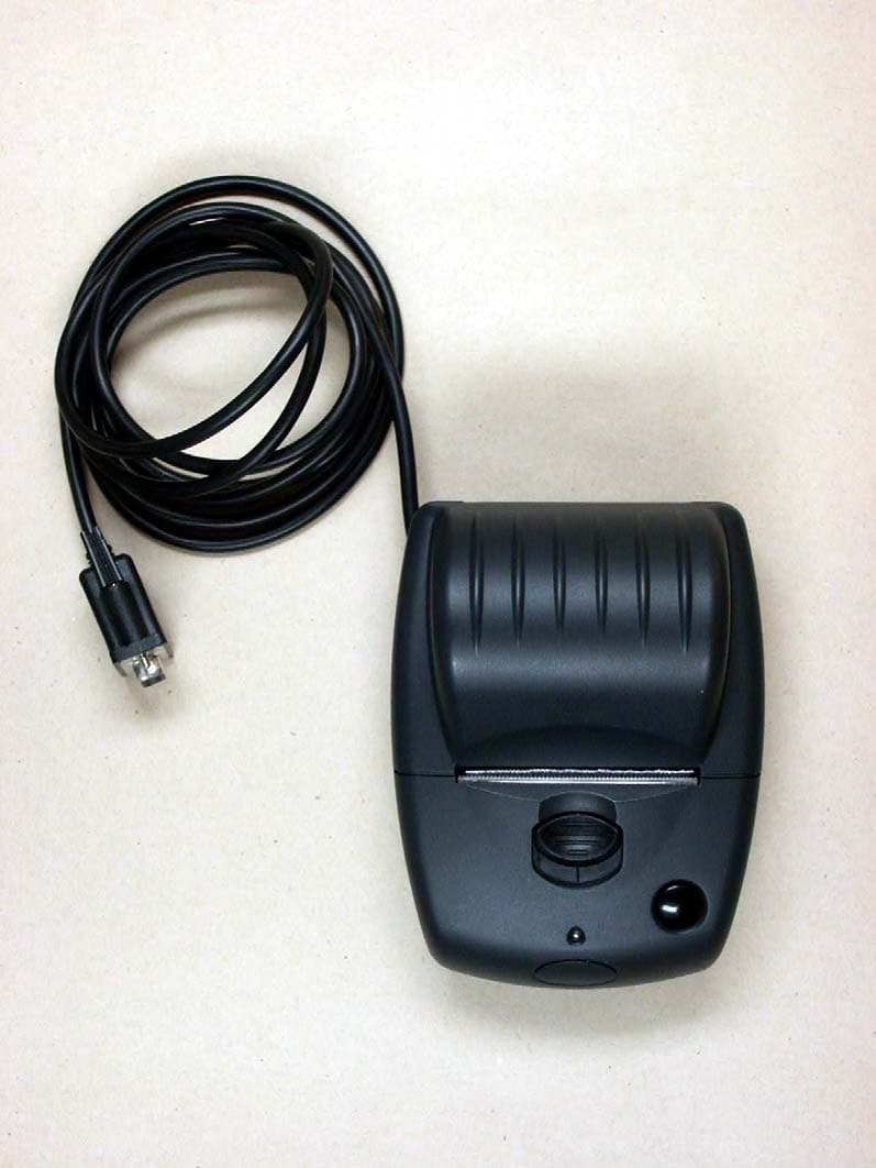
TGZAP13XXBT
Dec 06, 2006Bluetooth Printer
Equipment Class
JBP - Part 15 Class B Computing Device Peripheral