TIADR1500Doppler Speed Radar
Houston Radar LLC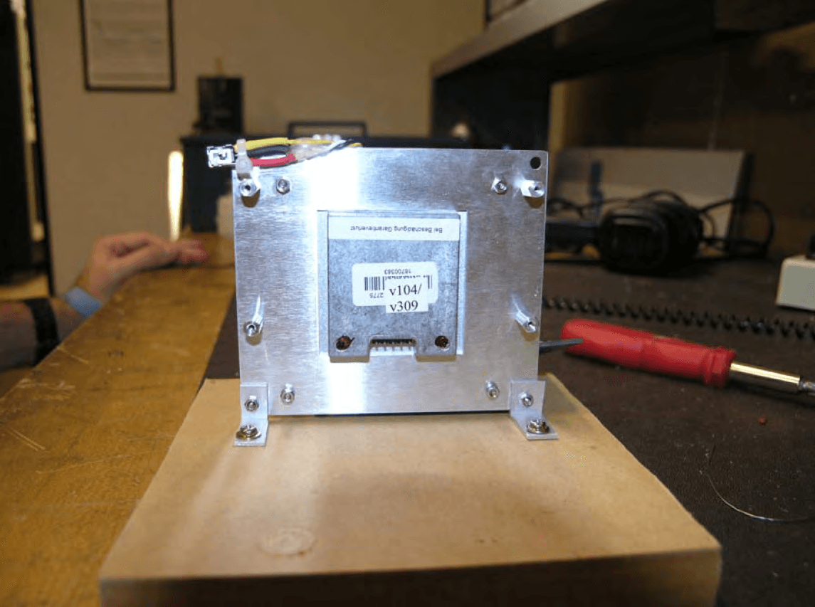
Click to zoom
Application Details
- Equipment Class
- FDS - Part 15 Field Disturbance Sensor
- Date of Grant
- Mar 27, 2008
- Application Purpose
- Original Equipment
- Date of Application
- Mar 26, 2008
- Equipment Note
- Doppler Speed Radar
- Frequency Range
- 24075.00000000 - 24175.00000000
- Company
- Houston Radar LLC
- Country
- United States
Documents & Files
Document Text
Text extracted from the exhibit documents filed with the FCC. Open a document above to read the original.
Users Manual
Page 1 of 13 Houston Radar LLC Installation and User Manual For Doppler Radar DR-1500 Houston Radar LLC 13814 Sherburn Manor Dr. Cypress .TX Http://www.Houston-Radar.com Email: [email protected] Contact: (281) 382-7303 Rev 1, Oct 25 th 2007 Page 2 of 13 This device complies with part 15 of the FCC Rules. Operation is subject to the following two conditions: (1) this device may not cause harmful interference, and (2) this device must accept any interference received, including interference that may cause undesired operation. Changes or modifications not expressly approved by the party responsible for compliance could void the user's authority to operate the equipment. Any modification or use other than specified in this manual will strictly void the certification to operate the device. Page 3 of 13 Table Of Contents INTRODUCTION .............................................................................................................. 4 INSTALLATION ............................................................................................................... 5 Mounting:........................................................................................................................ 5 Direction Pointing:.......................................................................................................... 5 Hookup:........................................................................................................................... 5 Wire Signal Descriptions: ............................................................................................... 7 USE ..................................................................................................................................... 7 Infrared Remote Programming: ...................................................................................... 8 DR-1500 SPECIFICATIONS ........................................................................................... 13 General .......................................................................................................................... 13 Data Interfaces .............................................................................................................. 13 Mechanical .................................................................................................................... 13 Performance .................................................................................................................. 13 Advanced Statistics ....................................................................................................... 13 Page 4 of 13 INTRODUCTION Congratulations on your purchase of the Houston Radar LLC’s directional Doppler speed radar DR-1500. This state of the art K-band microwave Doppler speed radar is specifically designed for the license free, battery operated speed radar market, for use in speed awareness trailers, school zones and other speed restricted traffic zone speed awareness uses. Utilizing the latest in high performance, ultra low power DSP (Digital Signal Processing) technology, you will find that this high quality product meets your exacting standards for performance and reliability. Some of the highlights of this product include: 9 FCC approved for your convenience and piece of mind 9 Advanced DSP based performance yields consistent performance and speed detection 9 Standard serial port hookup and data format allows hassle free use in existing systems o Use in place of existing products o Interface to your message displays o Use in your speed trailers o Use in school zones 9 31mA power usage is up to 10X lower vs. competing solutions and allows use of smaller batteries and solar panels- saving you cost 9 Ultra slim profile allows mounting in virtually any location 9 Built in clock/calendar keeps time even with DC power removed 9 Only 1 mA power consumption in standby mode 9 Optional infrared remote control allows you to change/set radar parameters including: o Min/Max speed limit of detection o Speed limit setting for flashing display digits o Sensitivity setting for changing detection range o Internal clock/calendar o Serial port settings o Radar built in self test 9 Now Featuring Optional integrated advanced statistics package with: o Multi-vehicle/multi-lane tracking allows better accuracy over competing units o 2 months of speed as well as count statistics saved in internal memory o Real time clock keeps stats with date/time o Unmatched Windows™ based “Stats Analyzer” software to download, manage, analyze and plot your stats information from all your DR-1500 radars available as option Page 5 of 13 INSTALLATION Mounting: The DR-1500 is supplied with a mounting plate and may be conveniently mounted via 4 mounting holes inside your enclosure. Use a “split washer” is used to ensure the mounting screw remains tight under vibration. Direction Pointing: The DR-1500 is directional in nature. It rejects traffic moving away from it and only measures oncoming traffic. If the optional stats analyzer feature is purchased with the unit, stats will only be collected for incoming traffic. This allows you to position the unit in a median without worry of picking up traffic on the outgoing lane For optimal performance, keep in mind the following: 9 Radar should be mounted with the circuit board horizontal to the road. 9 Radar should be pointed into the direction of the oncoming traffic. 9 Radar should be placed along the size of the road to minimize the angle of the oncoming traffic to the radar. o If radar cannot be placed right along the side of the road, it should be pointed at least 200-300 feet up the road into oncoming traffic. 9 The radar may pickup rotating fans. Avoid pointing it at fans or compressors. 9 Radar should be mounted at least 3+ feet high from the road for optimal performance. Hookup: Power Input : The DR-1500 radar can be powered from a nominal 12V DC battery and features industry leading operation…
Text truncated - open the document above for the full version.
Cover Letter(s)
http://www.Houston-Radar.com Email: [email protected] 13814 Sherburn Manor Dr. Cypress. TX. 77429 (281)-382-7303 1006 Rosemeadow Dr. Houston, TX. 77094 Agent’s Authorization Letter October 29 th 2007 I, an officer of Houston Radar LLC, do hereby authorize, until further notice, Professional Testing (EMI) Inc. of 1601 FM1460 Suite B. Round Rock TX 78664, to act on our professional behalf in dealings before the Federal Communications Commission with respect to all matters relating to equipment authorizations under 47CFR. This authorization includes, but it not limited to, the signing of Form 731. I certify that no party (as defined in 47 CFR 1.2002) to this application, including myself, is subject to a denial of federal benefits, including FCC benefits, pursuant to section 5301 of the anti-drug abuse act of 1988, 21 U.S.C., 853A. Certified By: (Vipin Malik) Chairman & CEO Houston Radar LLC
Cover Letter(s)
http://www.Houston-Radar.com Email: [email protected] 13814 Sherburn Manor Dr. Cypress. TX. 77429 (281)-382-7303 1006 Rosemeadow Dr. Houston, TX. 77094 Date: October 29 th 2007 To: Federal Communications Commission 7435 Oakland Mills Road Columbia, MD 21046-1069 Professional Testing (EMI) Inc. 1601 Round Rock, TX 78664 Subject: Confidentiality Request Application: Houston Radar LLC 13814 Sherburn Manor Dr. Cypress. TX 77429 Gentlemen: We, Houston Radar LLC, request that the schematic diagrams, system block diagrams and circuit/technical descriptions submitted with the application for certification for <insert FCC ID here> be withheld from public disclosure as per Section 0.459 of FCC rules. This request is made under the provisions of Section 0.457(d) of the Commission’s Rules, and Section 552(b)(4) of the Freedom of Information Act. These sections authorize as a withholding from public inspection, material which would be privileged as a matter of law if retained by the person submitting them, and material which would not customarily be released to the public by that person. The materials contain technical data, which would customarily be guarded from competitors. Sincerely, (Vipin Malik) Chairman & CEO Houston Radar LLC
Cover Letter(s)
On behalf of Houston Radar, LLC, Professional Testing (EMI), Inc. is seeking a modular approval for the DR1500 Doppler Radar. Requirements listed in FCC Public Notice DA 00-1407 are addressed below. 1) The device has a RF shield installed. The RF portion of the device is a Gunn Oscillator which is enclosed in a solid metal case. Please refer to the internal photographs. 2) The external data inputs are routed to a microcontroller. All of the data inputs are buffered. 3) The RF portion of the device contains internal power supply regulation. 4) The antenna requirement is addressed in the test report. 5) The module was tested in a stand alone configuration. It is intended to be used as a Serial device. While testing the unit was powered using an external 12 Volt Battery 6) A sticker is affixed to the back side of the EUT. The manual contains the explicit directions to label the exterior of the the device into which the EUT is integrated with “Contains FCC ID:TIADR1500”. 7) The Users Manual explains that any modifications may strictly void the certification and a separate approval must be obtained. 8) The device is very low power. The maximum rated power of the device is 5mW. The device is not intended to be mounted within 20 cm of a human. The device is therefore exempt from SAR evaluation.
Cover Letter(s)
1601 FM 1460, Suite B Round Rock, TX 78664 e-mail: [email protected] (512)244-3371 Fax: (512)244-1846 March 24, 2008 FCC ID: TIADR1500 In response to your comments regarding the application for certification of the device referenced above please find our response below: 1.) Users Manual must have Pt. 15.21 statement. The Users Manual has been updated to reflect the Pt. 15.21 statement. 2.) Modular Approvals need to have power line conducted test included as there are no guarantees that the end user will not connect to power grid. This can be accomplished using any store bought power converter. Conducted Emissions testing has been completed. The test report and test setup photos have been updated. 3.) Question 7 in modular approval letter is not in the user manual. Please revise user manual. The Users Manual has been updated to address Question 7.
ID Label/Location Info
Label Location Houston Radar LLC DR1500 FCC ID: TIADR1500 Cypress. TX. U.S.A.
Test Report
Professional Testing (EMI), Inc. Project 08198-10 Page 1 of 19 Project Number: 08198-10 Prepared for: Houston Radar, LLC. 13814 Sherburn Manor Drive Cypress, TX 77429 By Professional Testing (EMI), Inc. 1601 FM 1460, Suite B Round Rock, Texas 78664 November 2007 March 2008 CERTIFICATION Electromagnetic Interference Test Report Houston Radar, LLC. DR1500 Doppler Radar Professional Testing (EMI), Inc. Project 08198-10 Page 2 of 19 Table of Contents Title Page .........................................................................................................................................1 Table of Contents .............................................................................................................................2 Certificate of Compliance ................................................................................................................3 1.0 EUT Description ..................................................................................................................4 1.1 Applicable Documents.....................................................................................................4 1.2 EUT Operation.................................................................................................................4 2.0 Electromagnetic Emissions Testing.....................................................................................4 2.1 Radiated Emissions Measurements .................................................................................5 2.1.1 Test Procedure .........................................................................................................5 2.1.2 Test Criteria .............................................................................................................6 2.1.3 Test Results ..............................................................................................................6 3.0 Occupied Bandwidth Measurements ...................................................................................7 3.1 Test Procedure .................................................................................................................7 3.2 Test Criteria .....................................................................................................................7 3.3 Test Results ......................................................................................................................7 4.0 Antenna Requirement ..........................................................................................................7 4.1 Evaluation Procedure .......................................................................................................7 4.2 Evaluation Criteria ...........................................................................................................8 4.3 Evaluation Results ...........................................................................................................8 5.0 Modifications to Equipment ................................................................................................8 6.0 List of Test Equipment.........................................................................................................9 FIGURES Figure 1 Radiated Emissions Test Setup .......................................................................................10 APPENDICES Appendix A Emissions Data ..........................................................................................................11 THIS REPORT SHALL NOT BE REPRODUCED EXCEPT IN FULL, WITHOUT THE WRITTEN APPROVAL OF PROFESSIONAL TESTING (EMI), INC. Professional Testing (EMI), Inc. Project 08198-10 Page 3 of 19 Applicant: Houston Radar, LLC. Applicant’s Address: 13814 Sherburn Manor Drive Cypress, TX 77429 FCC ID: TIADR1500 Project Number: 08198-10 Test Dates: I, Michael A. Royer, for Professional Testing (EMI), Inc., being familiar with the FCC and IC rules and test procedures have reviewed the test setup, measured data and this report. I believe them to be true and accurate. The Houston Radar, LLC., DR1500 Doppler Radar was tested to and found to be in compliance with FCC Part 15 Subpart C for an Intentional Radiator. The highest emissions generated by the above equipment are listed below: Frequency (MHz) Level (dBμV/m) Limit (dBμV/m) Margin (dB) Fundamental 24142 120.7 137.5 -16.8 Spurious 7246 50.1 54 -3.9 Occupied Bandwidth 350 (kHz) Jason Anderson Director of Testing Services This report has been reviewed and accepted by Houston Radar, LLC.. The undersigned is responsible for ensuring that Houston Radar, LLC, DR1500 Doppler Radar will continue to comply with the FCC and IC rules. Certificate Of Compliance Professional Testing (EMI), Inc. Project 08198-10 Page 4 of 19 1.0 EUT Description The DR-1500 is a Doppler speed radar is powered by 12V DC nominal voltage. The microwave Gunn oscillator in the transceiver generates a 24.1 GHz signal and sends it continuously out of the patch antenna at the target. The signal also "illuminates" internal (to the microwave transceiver) mixer diodes that act as a receiver mixer. The transmitted radar waves are reflected off the moving target, change the reflected microwave frequency per the well-known "Doppler principle" and are received by the same transmitting horn antenna and mixed in the receiving mixer diodes with the local oscillator. The difference in the transmitted/received frequencies is produced as a low frequency (audio frequency range) out of the mixer diode and into the preamp. The system tested consisted of the following: Manufacturer & Model FCC Number Description Houston Radar, LLC., DR1500 TIADR1500 Doppler Radar 1.1 Applicable Documents Guidelines FCC Rule Parts Part 15 Transmitter Characteristics 15.245 Spurious Radiated Power 15.205, 15.209, 15.245 Antenna Requirement 15.203 Spurious Conducted Emissions 15.207 1.2 EUT Operation The EUT was operated in continuous transmit mode at max power to measure fundamental, …
Text truncated - open the document above for the full version.
Contact Information
Applicant
Vipin Malik(CEO)
Technical Contact
Professional Testing Inc.Jason Anderson
[email protected]512-244-3371
1601 FM 1460 Suite B · Round Rock, Texas · United States
Test Firm
Professional Testing (EMI), Inc.Michael Royer
Technical Specifications
| # | Rule Parts | Frequency Range | Power Output |
|---|---|---|---|
| 1 | 15.245 | 24.07 GHz - 24.18 GHz | - |
Other Applications from Houston Radar LLC

TIAPD310
Nov 14, 2014FMCW Vehicular traffic sensor module.
Equipment Class
DXX - Part 15 Low Power Communication Device Transmitter
TIADC310
Sep 10, 2013DC310 Field Sensor Module
Equipment Class
FDS - Part 15 Field Disturbance Sensor
TIAPD300
Aug 02, 2011K-Band FMCW Ranging Radar
Equipment Class
DXX - Part 15 Low Power Communication Device Transmitter
TIADR500
Aug 19, 2005DR500 Doppler Radar
Equipment Class
FDS - Part 15 Field Disturbance Sensor