TIADR500DR500 Doppler Radar
Houston Radar LLC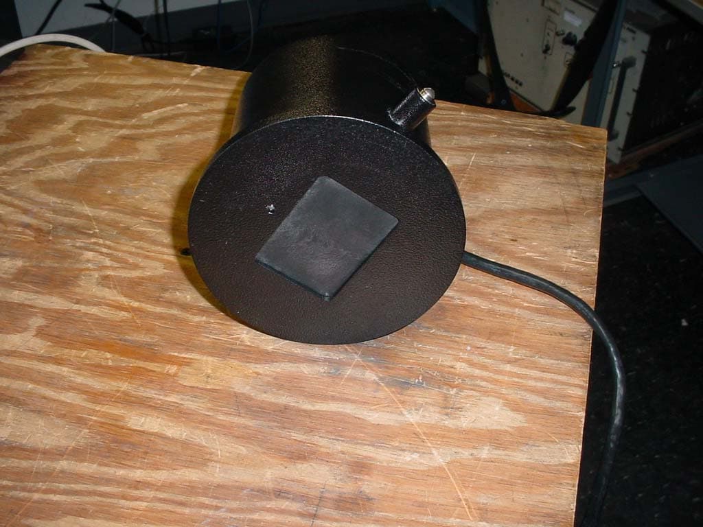
Click to zoom
Application Details
- Equipment Class
- FDS - Part 15 Field Disturbance Sensor
- Date of Grant
- Aug 19, 2005
- Application Purpose
- Original Equipment
- Date of Application
- Aug 19, 2005
- Equipment Note
- DR500 Doppler Radar
- Frequency Range
- 24142.00000000 - 24142.00000000
- Company
- Houston Radar LLC
- Country
- United States
Documents & Files
Document Text
Text extracted from the exhibit documents filed with the FCC. Open a document above to read the original.
Users Manual
Houston Radar LLC Installation and User Manual For Doppler Radar DR-500 Houston Radar LLC 13814 Sherburn Manor Dr. Cypress .TX Http://www.Houston-Radar.com Email: [email protected] Contact: (281) 382-7303 This device complies with part 15 of the FCC Rules. Operation is subject to the following two conditions: (1) this device may not cause harmful interference, and (2) this device must accept any interference received, including interference that may cause undesired operation. Table Of Contents Table Of Contents ........................................................................................................... 3 INTRODUCTION .............................................................................................................. 4 INSTALLATION ............................................................................................................... 4 Mounting:........................................................................................................................ 4 Direction Pointing:.......................................................................................................... 4 Hookup:........................................................................................................................... 5 USE ..................................................................................................................................... 6 Infrared Remote Programming: ...................................................................................... 6 DR-500 SPECIFICATIONS ............................................................................................... 9 General ............................................................................................................................ 9 Data Interfaces ................................................................................................................9 Mechanical ......................................................................................................................9 Performance ....................................................................................................................9 INTRODUCTION Congratulations on your purchase of the Houston Radar LLC’s directional doppler speed radar DR-500. This state of the art K-band microwave Doppler speed radar is specifically designed for the license free, battery operated speed radar market, for use in speed awareness trailers, school zones and other speed restricted traffic zone speed awareness uses. Utilizing the latest in high performance, ultra low power DSP (Digital Signal Processing) technology, you will find that this high quality product meets your exacting standards for performance and reliability. Some of the highlights of this product include: 9 FCC approved for your convenience and piece of mind 9 Advanced DSP based performance yields consistent performance and speed detection 9 Standard serial port hookup and data format allows hassle free use in existing systems o Use in place of existing products o Interface to your message displays o Use in your speed trailers o Use in school zones 9 Up to 5X lower operational power consumption vs. competing solutions allows use of smaller batteries and solar panels- saving you cost 9 Rugged weatherproof enclosure features side mounts and short depth 9 Built in clock/calendar allows pre-programmed times of operation 9 Only 50 micro amps power consumption in standby mode 9 Optional infrared remote control allows you to change/set: o Min/Max speed limit of detection o Internal clock/calendar and operational times o Serial port settings INSTALLATION Mounting: The DR-500 is supplied in a weatherproof enclosure and may be conveniently mounted via the side-mounting bosses, outside the speed trailer enclosure to facilitate pointing it into the oncoming traffic. Two #8-10 size screws are required for side boss mounting (provided). Care must be take to ensure that the provided “split washer” is used to ensure the mounting screw remains tight under vibration. Direction Pointing: The DR-500 is directional in nature. It rejects traffic moving away from it and only measures oncoming traffic. For optimal performance, keep in mind the following: 9 Radar should be mounted with the mounting bosses horizontal to the road. 9 Radar should be pointed into the direction of the oncoming traffic. 9 Radar should be placed along the size of the road to minimize the angle of the oncoming traffic to the radar. o If radar cannot be placed right along the side of the road, it should be pointed at least 200-300 feet up the road into oncoming traffic. 9 The radar will pickup rotating fans. Avoid pointing it at fans or compressors. 9 Radar should be mounted at least 3 feet off the road for optimal performance. Hookup: Power Input : The DR-500 radar is designed to be powered from a nominal 12V DC battery and features industry leading operational power consumption, which can be as low as 5X less than other similar radar designs on the market. This operational power translates directly into a longer battery life or gives you an option to power the unit from smaller batteries which would also require smaller solar panels for charging resulting in material cost savings in an entire solar charged battery operated speed awareness trailer. Serial Connection : The DR-500 features a dual RS232 and RS485 output that are active at the same time giving the user an option to connect serial outputs to either port (see serial port diagram). Speed data is output serially in mph as three ASCII digits in the following format: nnn\n\r where: nnn : The three digit ASCIII speed digits in mph \n\r : A new line followed by a carriage return character This format is compatible with other industry formats including a standard RS232 serial port on a PC, message boards and speed displays. Log/Statistics Storage : The DR-500 radar has capacity to store up to 4Mb of traffic statistics and feature…
Text truncated - open the document above for the full version.
Cover Letter(s)
http://www.Houston-Radar.com Email: [email protected] 13814 Sherburn Manor Dr. Cypress. TX. 77429 (281)-382-7303 1006 Rosemeadow Dr. Houston, TX. 77094 Date: July 25, 2005 To: Federal Communications Commission 7435 Oakland Mills Road Columbia, MD 21046-1069 Professional Testing (EMI) Inc. 1601 Round Rock, TX 78664 Subject: Confidentiality Request Application: Houston Radar LLC 13814 Sherburn Manor Dr. Cypress. TX 77429 Gentlemen: We, Houston Radar LLC, request that the schematic diagrams, system block diagrams and circuit/technical descriptions submitted with the application for certification for TIADR500 be withheld from public disclosure as per Section 0.459 of FCC rules. This request is made under the provisions of Section 0.457(d) of the Commission’s Rules, and Section 552(b)(4) of the Freedom of Information Act. These sections authorize as a withholding from public inspection, material which would be privileged as a matter of law if retained by the person submitting them, and material which would not customarily be released to the public by that person. The materials contain technical data, which would customarily be guarded from competitors. Sincerely, (Vipin Malik) Chairman & CEO Houston Radar LLC
Cover Letter(s)
American Telecommunications Certification Body Inc. 6731 Whittier Ave, McLean, VA 22101 August 17, 2005 RE: FCC ID: TIADR500_ATCB002684 Attention: Jason Anderson I have a few comments on this Application. Please note that further comments may arise in response to answers provided to the questions below. 1. Please provide the equipment code for this device on the 731 form. 2. Please complete section IV of the 731 by providing the name and position of the person responsible for the application and attesting to the non drug statement. 3. Please note that this is not a modular device as defined in DA001407. The FCC ID number is listed as being on the larger circular Black container and not on the transmitter module itself. As such, the device is more adequately defined as an end product. As such the device would receive its own FCC ID number (as shown by placing the ID on the case), but it would not be necessary to apply the modular approval route. A modular approval for this device would place the FCC ID on the transmitter board/module itself. 4. Please note that the 731 form states the device operates under 15.245 but the test report states the device was tested to 15.231(e). Please explain and please be consistent in all documentation. Please correct all documentation as needed. 5. Please note that the test report states the operating frequency is 418MHz, but other documentation (i.e. operational description, 731, manual etc) states the device operates in the 24GHz range. Please explain and please provide consistent documentation. Please correct all documentation as needed and please provide a report that is in accordance with the frequency, limits and rule part for the device. 6. Please note that the test report states that the antenna was ‘ Shortened the antenna element to a length of 12 cm”. Please note that the operational description states the operating antenna is a horn. Please explain. 7. Please note that the operational description states that the device is a Doppler radar. The bandwidth plots do not appear to indicate this type device. Please explain. 8. Please note that the Block diagram shows that the device operates on two available channels. Please provide test data for both channels. Dennis Ward mailto:[email protected] The items indicated above must be submitted before processing can continue on the above referenced application. Failure to provide the requested information may result in application termination. Correspondence should be considered part of the permanent submission and may be viewed from the Internet after a Grant of Equipment Authorization is issued. Please do not respond to this correspondence using the email reply button. In order for your response to be processed expeditiously, you must submit your documents through the AmericanTCB.com website. Also, please note that partial responses increase processing time and should not be submitted. Any questions about the content of this correspondence should be directed to the sender.
Cover Letter(s)
1601 FM 1460, Suite B Round Rock, TX 78664 e-mail: [email protected] 512/244-3371 Fax: (512)244-1846 August 18, 2005 FCC ID: TIADR500 In response to your comments regarding the application for certification of the devices referenced above please find our response below: 1. Please provide the equipment code for this device on the 731 form. Done. Uploaded. 2. Please complete section IV of the 731 by providing the name and position of the person responsible for the application and attesting to the non drug statement. Done. Uploaded. 3. Please note that this is not a modular device as defined in DA001407. The FCC ID number is listed as being on the larger circular Black container and not on the transmitter module itself. As such, the device is more adequately defined as an end product. As such the device would receive its own FCC ID number (as shown by placing the ID on the case), but it would not be necessary to apply the modular approval route. A modular approval for this device would place the FCC ID on the transmitter board/module itself. I would like to discuss this with you. 4. Please note that the 731 form states the device operates under 15.245 but the test report states the device was tested to 15.231(e). Please explain and please be consistent in all documentation. Please correct all documentation as needed. Somehow the wrong report was PDF’ed. The correct one will be uploaded. 5. Please note that the test report states the operating frequency is 418MHz, but other documentation (i.e. operational description, 731, manual etc) states the device operates in the 24GHz range. Please explain and please provide consistent documentation. Please correct all documentation as needed and please provide a report that is in accordance with the frequency, limits and rule part for the device. Somehow the wrong report was PDF’ed. The correct one will be uploaded. 6. Please note that the test report states that the antenna was ‘Shortened the antenna element to a length of 12 cm”. Please note that the operational description states the operating antenna is a horn. Please explain. Somehow the wrong report was PDF’ed. The correct one will be uploaded. 7. Please note that the operational description states that the device is a Doppler radar. The bandwidth plots do not appear to indicate this type device. Please explain. Somehow the wrong report was PDF’ed. The correct one will be uploaded. 8. Please note that the Block diagram shows that the device operates on two available channels. Please provide test data for both channels. The two channels you see are two separate outputs from the mixer diodes. This allows the system to calculate the direction of the moving target, i.e. approaching, moving away.
Cover Letter(s)
http://www.Houston-Radar.com Email: [email protected] 13814 Sherburn Manor Dr. Cypress. TX. 77429 (281)-382-7303 1006 Rosemeadow Dr. Houston, TX. 77094 Agent’s Authorization Letter July 25 th 2005 I, an officer of Houston Radar LLC, do hereby authorize, until further notice, Professional Testing (EMI) Inc. of 1601 FM1460 Suite B. Round Rock TX 78664, to act on our professional behalf in dealings before the Federal Communications Commission with respect to all matters relating to equipment authorizations under 47CFR. This authorization includes, but it not limited to, the signing of Form 731. I certify that no party (as defined in 47 CFR 1.2002) to this application, including myself, is subject to a denial of federal benefits, including FCC benefits, pursuant to section 5301 of the anti-drug abuse act of 1988, 21 U.S.C., 853A. Certified By: (Vipin Malik) Chairman & CEO Houston Radar LLC
External Photos
Houston Radar LLC 24 GHz Radar Front Rear Houston Radar LLC 24 GHz Radar Housing
ID Label/Location Info
Houston Radar LLC Doppler Radar DR500 Http: // Houston-Radar.com Cypress. TX. U.S.A FCC ID: TIADR500 Serial #:
Internal Photos
Houston Radar LLC 24 GHz Radar Houston Radar LLC 24 GHz Radar Houston Radar LLC 24 GHz Radar
Test Report
Exhibit B Test Report Houston Radar, LLC. DR500 Doppler Radar Professional Testing (EMI), Inc. Project 05232-10 Page 1 of 13 Project Number: 06073-10 Prepared for: Houston Radar, LLC. 13814 Sherburn Manor Drive Cypress, TX 77429 By Professional Testing (EMI), Inc. 1601 FM 1460, Suite B Round Rock, Texas 78664 August 2005 CERTIFICATION Electromagnetic Interference Test Report Houston Radar, LLC. DR500 Doppler Radar Professional Testing (EMI), Inc. Project 05232-10 Page 2 of 13 Table of Contents Title Page .........................................................................................................................................1 Table of Contents .............................................................................................................................2 Certificate of Compliance ................................................................................................................3 1.0 EUT Description ..................................................................................................................4 1.1 Applicable Documents.....................................................................................................4 1.2 EUT Operation.................................................................................................................4 2.0 Electromagnetic Emissions Testing.....................................................................................4 2.1 Radiated Emissions Measurements .................................................................................4 2.1.1 Test Procedure .........................................................................................................5 2.1.2 Test Criteria .............................................................................................................5 2.1.3 Test Results ..............................................................................................................5 3.0 Occupied Bandwidth Measurements ...................................................................................7 3.1 Test Procedure .................................................................................................................7 3.2 Test Criteria .....................................................................................................................7 3.3 Test Results ......................................................................................................................7 4.0 Antenna Requirement ..........................................................................................................7 4.1 Evaluation Procedure .......................................................................................................7 4.2 Evaluation Criteria ...........................................................................................................8 4.3 Evaluation Results ...........................................................................................................8 5.0 Modifications to Equipment ................................................................................................8 6.0 List of Test Equipment.........................................................................................................8 FIGURES Figure 1 Radiated Emissions Test Setup .........................................................................................8 APPENDICES Appendix A Emissions Data ............................................................................................................9 THIS REPORT SHALL NOT BE REPRODUCED EXCEPT IN FULL, WITHOUT THE WRITTEN APPROVAL OF PROFESSIONAL TESTING (EMI), INC. Professional Testing (EMI), Inc. Project 05232-10 Page 3 of 13 Applicant: Houston Radar, LLC. Applicant’s Address: 13814 Sherburn Manor Drive Cypress, TX 77429 FCC ID: TIADR500 Project Number: 06073-10 Test Dates: I, Michael A. Royer, for Professional Testing (EMI), Inc., being familiar with the FCC and IC rules and test procedures have reviewed the test setup, measured data and this report. I believe them to be true and accurate. The Houston Radar, LLC., DR500 Doppler Radar was tested to and found to be in compliance with FCC Part 15 Subpart C for an Intentional Radiator. The highest emissions generated by the above equipment are listed below: Frequency (MHz) Level (dBμV/m) Limit (dBμV/m) Margin (dB) Fundamental 24142 120.7 137.5 -16.8 Spurious 72420 96.4 97.5 -1.1 Occupied Bandwidth 350 (kHz) Michael A. Royer, BSEE, NCE EMC Department Manager This report has been reviewed and accepted by Houston Radar, LLC.. The undersigned is responsible for ensuring that Houston Radar, LLC., DR500 Doppler Radar will continue to comply with the FCC rules. Certificate Of Compliance Professional Testing (EMI), Inc. Project 05232-10 Page 4 of 13 1.0 EUT Description The DR-500 is a Doppler speed radar is powered by 12V DC nominal voltage. The microwave Gunn oscillator in the transceiver generates a 24.14GHz signal and sends it continuously out of the horn antenna at the target. The signal also "illuminates" internal (to the microwave transceiver) mixer diodes that act as a receiver mixer. The transmitted radar waves are reflected off the moving target, change the reflected microwave frequency per the well-known "Doppler principle" and are received by the same transmitting horn antenna and mixed in the receiving mixer diodes with the local oscillator. The difference in the transmitted/received frequencies is produced as a low frequency (audio frequency range) out of the mixer diode and into the preamp. The system tested consisted of the following: Manufacturer & Model FCC Number Description Houston Radar, LLC., DR500 TIADR500 Doppler Radar 1.1 Applicable Documents Guidelines FCC Rule Parts Part 15 Transmitter Characteristics 15.245 Spurious Radiated Power 15.205, 15.209, 15.245 Antenna Requirement 15.203 1.2 EUT Operation The EUT was operated in continuous transmit mode at max power to measure fu…
Text truncated - open the document above for the full version.
Test Setup Photos
Houston Radar LLC 24 GHz Radar Radiated Emissions – Front Radiated Emissions – Back Houston Radar LLC 24 GHz Radar
Contact Information
Applicant
Vipin Malik(CEO)
Technical Contact
Professional Testing, Inc.Jason Anderson
1601 FM 1460 Suite B · Round Rock, Texas · United States
Test Firm
Professional Testing (EMI), Inc.Michael Royer
Technical Specifications
| # | Rule Parts | Frequency Range | Power Output |
|---|---|---|---|
| 1 | 15.245 | 24.14 GHz - 24.14 GHz | - |
Other Applications from Houston Radar LLC

TIAPD310
Nov 14, 2014FMCW Vehicular traffic sensor module.
Equipment Class
DXX - Part 15 Low Power Communication Device Transmitter
TIADC310
Sep 10, 2013DC310 Field Sensor Module
Equipment Class
FDS - Part 15 Field Disturbance Sensor
TIAPD300
Aug 02, 2011K-Band FMCW Ranging Radar
Equipment Class
DXX - Part 15 Low Power Communication Device Transmitter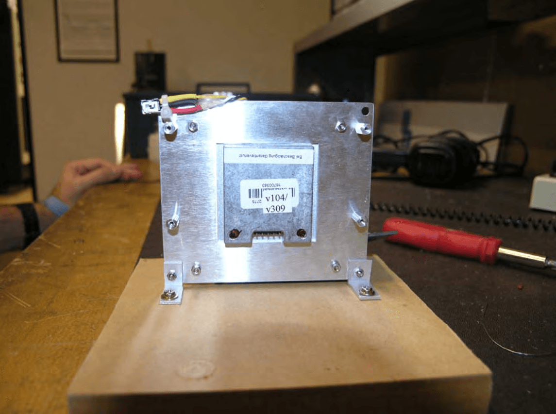
TIADR1500
Mar 27, 2008Doppler Speed Radar
Equipment Class
FDS - Part 15 Field Disturbance Sensor