TIH8731540Bluesocket 1540 Access Point
Bluesocket, Incorporated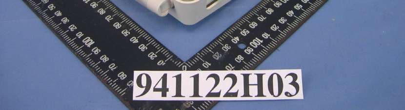
Click to zoom
Application Details
- Equipment Class
- NII - Unlicensed National Information Infrastructure TX
- Date of Grant
- Jan 12, 2006
- Application Purpose
- Original Equipment
- Date of Application
- Jan 11, 2006
- Equipment Note
- Bluesocket 1540 Access Point
- Frequency Range
- 5260.00000000 - 5320.00000000
- Company
- Bluesocket, Incorporated
- Country
- United States
Documents & Files
Document Text
Text extracted from the exhibit documents filed with the FCC. Open a document above to read the original.
Users Manual
BlueSecure™ Access Point 1540 Installation Guide Bluesocket, Inc. 10 North Avenue Burlington, MA 01803 USA +1 781-328-0888 www.bluesocket.com Part Number: 873-01540-M00 Document Version: 1.0 ii Copyright Notice Copyright © 2005 Bluesocket, Inc. All rights reserved. No part of this document may be reproduced in any form or by any means, electronic or manual, including photocopying without the written permission of Bluesocket, Inc. The products described in this document may be protected by one or more U.S. patents, foreign patents, or pending patents. This document is provided “as is” without warranty of any kind, either express or implied, including, but not limited to, the implied warranties of merchantability, fitness for a particular purpose, or non-infringement. This publication could include technical inaccuracies or typographical errors. Changes are periodically added to the information herein; these changes will be incorporated in new editions of the document. Bluesocket inc. may make improvements or changes in the products or the programs described in this document at any time. Trademarks Bluesocket, The Bluesocket Logo, Secure Mobility, BlueView, BlueSecure, HighDataDensity and CellularLAN are trademarks or registered trademarks of Bluesocket, Inc. All other trademarks, trade names and company names referenced herein are used for identification purposes only and are the property of their respective owners. BlueSecure™ AP 1540 Installation Guideiii Contents Overview .................................................................................................1 Familiarizing Yourself with the BSAP Hardware ............................................2 Fixed Antennas......................................................................................3 LED Indicators .......................................................................................3 Power Supply Connector ........................................................................4 Mounting Bracket Screw .........................................................................4 Ethernet/PoE Connector .........................................................................4 Reset Button ..........................................................................................4 Serial Console Port ................................................................................4 Kensington Security Slot..........................................................................5 802.11a/802.11bg External Antenna Connectors ....................................5 Provisioning Your Bluesocket WLAN for BSAPs .............................................5 Deploying BSAPs on the Same Layer-2 Subnet as the BSC ..........................6 Deploying BSAPs with Layer-3 Connectivity to the BSC ...............................6 Selecting a BSAP Installation Location ..........................................................8 Connecting and Powering the BSAP ............................................................8 Using the BSAP Command Line Interface (CLI).............................................10 Accessing the BSAP CLI ........................................................................10 Navigating the BSAP CLI ......................................................................10 BSAP Default Configuration...................................................................11 Setting the BSAP and Home BSC IP Addresses Using the CLI .....................12 General Specifications .............................................................................13 BSAP Wall Mounting Template .................................................................16 iv Contents BlueSecure™ Access Point 1540 Installation Guide1 Overview The BlueSecure Access Point 1540 is a next-generation, “thin” access point that works in conjunction with BlueSecure Controllers (BSCs) for enterprise wireless LAN (WLAN) deployments. BlueSecure Access Points (BSAPs) feature dual radios supporting 802.11a and 802.11b/g in a plenum-rated housing with fixed omni- directional antennas, and two reverse-SMA connectors supporting connection of external 802.11a and 802.11bg antennas. BSAPs are simple to configure and require only minimal provisioning to make them fully operational on a WLAN secured and managed by a BlueSecure Controller. BSAPs can be directly attached to any existing Layer-2 or Layer-3 Ethernet switch and communicate with the BSC across any subnet boundary. Once the BSAP has discovered and established Layer-2 or Layer-3 communication with its home (i.e., host) BlueSecure Controller, advanced configuration and provisioning may be applied either to individual BSAPs or globally across the entire WLAN using the BSC’s web-based Administrator Console. Once a BlueSecure Access Point has downloaded its configuration from its home BlueSecure Controller, the BSAP and the BSC will establish a tunnel through which all wireless client traffic received by the BSAP will pass for the application of policy by the BSC. You can configure BSAPs to function as access points or RF sensors. The BSC manages and configures BSAPs operating in AP-only mode, AP/sensor mode, or sensor-only mode, and uses BSAPs operating in AP/sensor and sensor mode to perform RF intrusion detection and containment. This guide provides complete installation procedures for your BSAP including: • familiarizing yourself with the BSAP hardware • provisioning your Bluesocket WLAN for BSAPs • selecting a BSAP installation location • connecting and powering the BSAP • using the BSAP command line interface (CLI) Figure 1: BSAPs Automatically Discover BSCs Across L2/L3 Networks 2 Familiarizing Yourself with the BSAP Hardware Figure 2 illustrates the BSAP hardware. Familiarize yourself with the labeled components before attempting to install the BSAP. Figure 2: BSAP Hardware Components Fixed Antennas LED Indicators Captive Mounting Bracket Screw Reset Button Power Supply Connector Ethernet/Po…
Text truncated - open the document above for the full version.
External Photos
Page 1 CONSTRUCTION PHOTOS OF EUT EUT with Antenna Model No.: S24493DS Page 2 EUT with Antenna Model No.: S24497P Page 3 EUT with Antenna Model No.: S2403BPX Page 4 EUT with Antenna Model No.: SR2405135D/ SR24135DA Page 5 EUT with Antenna Model No.: FDS_2FED01+I3G 941122H03 941122H03 Page 6
ID Label/Location Info
FCC ID: TIH8731540 FCC LABEL LOCATION The label will be permanently affixed at a conspicuous location on the device. Label
Internal Photos
Page 7 Page 8 Page 9 Page 10 Page 11 Page 12 Page 13 Page 14 Page 15 Antenna Model No.: S24493DS Page 16 Antenna Model No.: S24497P Page 17 Antenna Model No.: S2403BPX Page 18 Antenna Model No.: SR2405135D/ SR24135DA Page 19 Page 20 Page 21 Page 22
Operational Description
FCC ID: TIH8731540 Report No. RF941122H03 Technical Description This device is a Bluesocket 1540 Access Point operates in both the 5GHz and 2.4GHz bands with DSSS and OFDM technique. The transmitter rate could be 1/2/5.5/6/9/11/12/18/24/36/48/54Mbps. The transmitter of the EUT is powered by power adapter or POE. The antenna are as following: For 2.4GHz No.Model No. Gain (dBi) Antenna Type Antenna Connector 1S2403BPX5 dBi2.400-2.500 GHz Special Purpose Omni AntennaReverse SMA 2 SR2405135D/ SR24135DA 5 dBi PCS/DCS and 2.4 GHz Wide Angle Coverage Directional Antennas Reverse SMA 3S24493DS3 dBi Dual Band, Tri-mode 802.11b/a/g Spatial Diversity Omnidirectional Antenna Reverse SMA 4S24497P7 dBiDual Band, Tri-mode Directional AntennaReverse SMA 5FDS_2FED01+I3G3 dBiDual Band Antenna, DipoleMMCX For 5GHz No.Model No. Gain (dBi) Antenna Type Antenna Connector 1S24493DS3 dBi Dual Band, Tri-mode 802.11b/a/g Spatial Diversity Omnidirectional Antenna Reverse SMA 2S24497P8 dBiDual Band, Tri-mode Directional AntennaReverse SMA 3FDS_2FED01+I3G5 dBiDual Band Antenna, DipoleMMCX Note: 1. All of the above antennas are outdoor Antenna except the antenna model No.: FDS_2FED01+I3G. 2. All of the above antennas can be used in Point to Multi-point applications except the antenna model No.: FDS_2FED01+I3G. Under normal use condition, the user has to keep at least 20 cm separation distance between radiator and the body of the user. For more detailed instruction, please refer to the user’s manual. FCC ID: TIH8731540 Report No. RF941122H03 FCC 15.407(c) states : The device shall automatically discontinue transmission in case of either absence of information to transmit or operational failure. These provisions are not intended to preclude the transmission of control or signaling information or the use of repetitive codes used by certain digital technologies to complete frame or burst intervals. Applicants shall include in their application for equipment authorization a description of hoe this requirement is met. Data transmission is always initiated by software, which is then pass down through the MAC, through the digital and analog baseband, and finally to the RF chip. Several special packets (ACKs, CTS, PSPoll, etc...) are initiated by the MAC. There are the only ways the digital baseband portion will turn on the RF transmitter, which it then turns off at the end of the packet. Therefore, the transmitter will be on only while one of the aforementioned packets are being transmitted.
RF Exposure Info
FCC ID: TIH8731540 Report No.: SA941122H031Issued: Dec. 25, 2005 RF EXPOSURE REPORT REPORT NO.: SA941122H03 MODEL NO.: BSAP-1540 ACCORDING: FCC Guidelines for Human Exposure IEEE C95.1 APPLICANT: Bluesocket, Inc. ADDRESS: 10 North Avenue Burlington, MA 01803 ISSUED BY: Advance Data Technology Corporation LAB LOCATION: No. 81-1, Lu Liao Keng, 9 Ling, Wu Lung Tsuen, Chiung Lin Hsiang, Hsin Chu Hsien, Taiwan, R.O.C. FCC ID: TIH8731540 Report No.: SA941122H032Issued: Dec. 25, 2005 RF Exposure Measurement 1. Introduction In this document, we try to prove the safety of radiation harmfulness to the human body for our product. The limit for Maximum Permissible Exposure (MPE) specified in FCC 1.1310 is followed. The Gain of the antenna used in this product is measured in a Fully Anechoic Chamber (FAC) calibrated for antenna measurement in ADT, and also the maximum total power input to the antenna is measured. Through the Friis transmission formula and the maximum gain of the antenna, we can calculate the distance, away from the product, where the limit of MPE is reached. Although the Friis transmission formula is a far field assumption, the calculated result of that is an over-prediction for near field power density. We will take that as the worst case to specify the safety range. 2. RF Exposure Limit According to FCC 1.1310: The criteria listed in the following table shall be used to evaluate the environmental impact of human exposure to radio-frequency (RF) radiation as specified in 1.1307(b) LIMITS FOR MAXIMUM PERMISSIBLE EXPOSURE (MPE) Frequency Range (MHz) Electric Field Strength (V/m) Magnetic Field Strength (A/m) Power Density (mW/cm 2 ) Average Time (minutes) (A)Limits For Occupational / Control Exposures 300-1500......F/3006 1500-100,000......56 (B)Limits For General Population / Uncontrolled Exposure 300-1500......F/15006 1500-100,000......1.030 F = Frequency in MHz FCC ID: TIH8731540 Report No.: SA941122H033Issued: Dec. 25, 2005 3. Friis Formula Friis transmission formula : Pd = (Pout*G) / (4*pi*r 2 ) where Pd = power density in mW/cm 2 Pout = output power to antenna in mW G = gain of antenna in linear scale Pi = 3.1416 R = distance between observation point and center of the radiator in cm Pd is the limit of MPE, 1 mW/cm 2 . If we know the maximum Gain of the antenna and the total power input to the antenna, through the calculation, we will know the MPE value at distance 20cm. Ref. : David K. Cheng, Field and Wave Electromagnetics, Second Edition, Page 640, Eq. (11-133). 4 EUT Operating condition The software provided by Manufacturer enabled the EUT to transmit and receive data at lowest, middle and highest channel individually. 5. Classification This is a stand alone radio device. So under normal use condition, it is easy to be re- located in the place where at least 20 cm far away from the body of the user. Warning statement to the user for keeping at least 20cm or more separation distance with the antenna should be included in users manual. So, this device is classified as Mobile Device. FCC ID: TIH8731540 Report No.: SA941122H034Issued: Dec. 25, 2005 6 Test Results 6.1 Antenna Gain For 2.4GHz Antenna 1: The maximum Gain of the antenna is 5dBi or 3.162(numeric). Antenna 2: The maximum Gain of the antenna is 5dBi or 3.162(numeric). Antenna 3: The maximum Gain of the antenna is 3dBi or 1.995(numeric). Antenna 4: The maximum Gain of the antenna is 7dBi or 5.012(numeric). Antenna 5: The maximum Gain of the antenna is 3dBi or 1.995(numeric). For 5GHz Antenna 1: The maximum Gain of the antenna is 3dBi or 1.995(numeric). Antenna 2: The maximum Gain of the antenna is 8dBi or 6.310(numeric). Antenna 3: The maximum Gain of the antenna is 5dBi or 3.162 (numeric). For 2.4GHz No.Model No.Gain (dBi)Antenna TypeAntenna Connector 1S2403BPX5 dBi2.400-2.500 GHz Special Purpose Omni AntennaReverse SMA 2 SR2405135D/ SR24135DA 5 dBi PCS/DCS and 2.4 GHz Wide Angle Coverage Directional Antennas Reverse SMA 3S24493DS3 dBi Dual Band, Tri-mode 802.11b/a/g Spatial Diversity Omnidirectional Antenna Reverse SMA 4S24497P7 dBiDual Band, Tri-mode Directional AntennaReverse SMA 5FDS_2FED01+I3G3 dBiDual Band Antenna, DipoleMMCX For 5GHz No.Model No.Gain (dBi)Antenna TypeAntenna Connector 1S24493DS3 dBi Dual Band, Tri-mode 802.11b/a/g Spatial Diversity Omnidirectional Antenna Reverse SMA 2S24497P8 dBiDual Band, Tri-mode Directional AntennaReverse SMA 3FDS_2FED01+I3G5 dBiDual Band Antenna, DipoleMMCX Note: 1. All of the above antennas are outdoor Antenna except the antenna model No.: FDS_2FED01+I3G. FCC ID: TIH8731540 Report No.: SA941122H035Issued: Dec. 25, 2005 6.2 Output Power Into Antenna & RF Exposure value at distance 20cm: For 2.4GHz 802.11b: Antenna 1 Channel Channel Frequency (MHz) Output Power to Antenna (mW) Power Density (mW/cm 2 ) Limit of Power Density (mW/cm 2 ) 12412123.0270.0771.0 62437138.0380.0871.0 11246256.2340.0351.0 Antenna 2 Channel Channel Frequency (MHz) Output Power to Antenna (mW) Power Density (mW/cm 2 ) Limit of Power Density (mW/cm 2 ) 12412123.0270.0771.0 62437138.0380.0871.0 11246256.2340.0351.0 Antenna 3 Channel Channel Frequency (MHz) Output Power to Antenna (mW) Power Density (mW/cm 2 ) Limit of Power Density (mW/cm 2 ) 12412123.0270.0491.0 62437138.0380.0551.0 11246256.2340.0221.0 Antenna 4 Channel Channel Frequency (MHz) Output Power to Antenna (mW) Power Density (mW/cm 2 ) Limit of Power Density (mW/cm 2 ) 12412123.0270.1231.0 62437138.0380.1381.0 11246256.2340.0561.0 Antenna 5 Channel Channel Frequency (MHz) Output Power to Antenna (mW) Power Density (mW/cm 2 ) Limit of Power Density (mW/cm 2 ) 12412123.0270.0491.0 62437138.0380.0551.0 11246256.2340.0221.0 FCC ID: TIH8731540 Report No.: SA941122H036Issued: Dec. 25, 2005 802.11g: Antenna 1 Channel Channel Frequency (MHz) Output Power to Antenna (mW) Power Density (mW/cm 2 ) Limit of Power Density (mW/cm 2 ) 1241270.7950.0451.0 62437245.4710.1541.0 11246236.3080.0231.0 Antenna 2 Channel Channel Frequency (MHz) Output Power to Ant…
Text truncated - open the document above for the full version.
Test Report
FCC ID: TIH8731540 Report No.: RF941122H031Report Format Version 2.0.4 FCC TEST REPORT (15.247) REPORT NO.: RF941122H03 MODEL NO.: BSAP-1540 RECEIVED: Nov. 25, 2005 TESTED: Dec. 05 to 21, 2005 ISSUED: Dec. 23, 2005 APPLICANT: Bluesocket, Inc. ADDRESS: 10 North Avenue Burlington, MA 01803 ISSUED BY: Advance Data Technology Corporation TEST LOCATION: No. 81-1, Lu Liao Keng, 9 Ling, Wu Lung Tsuen, Chiung Lin Hsiang, Hsin Chu Hsien, Taiwan, R.O.C. This test report consists of 191 pages in total. It may be duplicated completely for legal use with the approval of the applicant. It should not be reproduced except in full, without the written approval of our laboratory. The client should not use it to claim product endorsement by CNLA, A2LA or any government agencies. The test results in the report only apply to the tested sample. The test results in this report are traceable to the national or international standards. 0536No. 2177-01 ILAC MRA FCC ID: TIH8731540 Report No.: RF941122H032Report Format Version 2.0.4 Table of Contents 1.CERTIFICATION....................................................................................................6 2.SUMMARY OF TEST RESULTS............................................................................7 3.GENERAL INFORMATION.....................................................................................9 3.1GENERAL DESCRIPTION OF EUT.......................................................................9 3.2DESCRIPTION OF TEST MODES.......................................................................11 3.2.1TEST MODE APPLICABILITY AND TESTED CHANNEL DETAIL:.......................12 3.3GENERAL DESCRIPTION OF APPLIED STANDARDS.......................................14 3.4DESCRIPTION OF SUPPORT UNITS..................................................................15 3.5CONFIGURATION OF SYSTEM UNDER TEST...................................................16 4.TEST TYPES AND RESULTS (802.11b & g, 2400 ~ 2483.5MHz Band)...............20 4.1CONDUCTED EMISSION MEASUREMENT........................................................20 4.1.1LIMITS OF CONDUCTED EMISSION MEASUREMENT......................................20 4.1.2TEST INSTRUMENTS..........................................................................................20 4.1.3TEST PROCEDURES..........................................................................................21 4.1.4DEVIATION FROM TEST STANDARD.................................................................21 4.1.5TEST SETUP.......................................................................................................22 4.1.6EUT OPERATING CONDITIONS.........................................................................22 4.1.7TEST RESULTS...................................................................................................23 4.2RADIATED EMISSION MEASUREMENT.............................................................27 4.2.1LIMITS OF RADIATED EMISSION MEASUREMENT...........................................27 4.2.2TEST INSTRUMENTS..........................................................................................28 4.2.3TEST PROCEDURES..........................................................................................29 4.2.4DEVIATION FROM TEST STANDARD.................................................................29 4.2.5TEST SETUP.......................................................................................................30 4.2.6EUT OPERATING CONDITIONS.........................................................................30 4.2.7TEST RESULTS (ANTENNA 1)............................................................................31 4.2.8TEST RESULTS (ANTENNA 2)............................................................................39 4.2.9TEST RESULTS (ANTENNA 3)............................................................................47 4.2.10TEST RESULTS (ANTENNA 4)............................................................................55 4.2.11TEST RESULTS (ANTENNA 5)............................................................................63 4.36dB BANDWIDTH MEASUREMENT....................................................................71 4.3.1LIMITS OF 6DB BANDWIDTH MEASUREMENT.................................................71 FCC ID: TIH8731540 Report No.: RF941122H033Report Format Version 2.0.4 4.3.2TEST INSTRUMENTS..........................................................................................71 4.3.3TEST PROCEDURE.............................................................................................72 4.3.4DEVIATION FROM TEST STANDARD.................................................................72 4.3.5TEST SETUP.......................................................................................................72 4.3.6EUT OPERATING CONDITIONS.........................................................................72 4.3.7TEST RESULTS...................................................................................................73 4.4MAXIMUM PEAK OUTPUT POWER....................................................................79 4.4.1LIMITS OF MAXIMUM PEAK OUTPUT POWER MEASUREMENT.....................79 4.4.2INSTRUMENTS....................................................................................................79 4.4.3TEST PROCEDURES..........................................................................................80 4.4.4DEVIATION FROM TEST STANDARD.................................................................80 4.4.5TEST SETUP.......................................................................................................80 4.4.6EUT OPERATING CONDITIONS.........................................................................80 4.4.7TEST RESULTS...................................................................................................81 4.5POWER SPECTRAL DENSITY MEASUREMENT.................................…
Text truncated - open the document above for the full version.
Test Report
FCC ID: TIH8731540 Report No.: RF941122H031Report Format Version 2.0.4 FCC TEST REPORT (15.407) REPORT NO.: RF941122H03 MODEL NO.: BSAP-1540 RECEIVED: Nov. 25, 2005 TESTED: Dec. 05 to 21, 2005 ISSUED: Dec. 23, 2005 APPLICANT: Bluesocket, Inc. ADDRESS: 10 North Avenue Burlington, MA 01803 ISSUED BY: Advance Data Technology Corporation TEST LOCATION: No. 81-1, Lu Liao Keng, 9 Ling, Wu Lung Tsuen, Chiung Lin Hsiang, Hsin Chu Hsien, Taiwan, R.O.C. This test report consists of 82 pages in total. It may be duplicated completely for legal use with the approval of the applicant. It should not be reproduced except in full, without the written approval of our laboratory. The client should not use it to claim product endorsement by CNLA, A2LA or any government agencies. The test results in the report only apply to the tested sample. The test results in this report are traceable to the national or international standards. 0536No. 2177-01 ILAC MRA FCC ID: TIH8731540 Report No.: RF941122H032Report Format Version 2.0.4 Table of Contents 1.CERTIFICATION....................................................................................................5 2.SUMMARY OF TEST RESULTS............................................................................6 3.GENERAL INFORMATION.....................................................................................7 3.1GENERAL DESCRIPTION OF EUT.......................................................................7 3.2DESCRIPTION OF TEST MODES.........................................................................9 3.2.1TEST MODE APPLICABILITY AND TESTED CHANNEL DETAIL:.......................10 3.3GENERAL DESCRIPTION OF APPLIED STANDARDS.......................................12 3.4DESCRIPTION OF SUPPORT UNITS..................................................................13 3.5CONFIGURATION OF SYSTEM UNDER TEST...................................................14 4.TEST TYPES AND RESULTS..............................................................................16 4.1CONDUCTED EMISSION MEASUREMENT........................................................16 4.1.1LIMITS OF CONDUCTED EMISSION MEASUREMENT......................................16 4.1.2TEST INSTRUMENTS..........................................................................................16 4.1.3TEST PROCEDURES..........................................................................................17 4.1.4DEVIATION FROM TEST STANDARD.................................................................17 4.1.5TEST SETUP.......................................................................................................18 4.1.6EUT OPERATING CONDITIONS.........................................................................18 4.1.7TEST RESULTS...................................................................................................19 4.2RADIATED EMISSION MEASUREMENT.............................................................23 4.2.1LIMITS OF RADIATED EMISSION MEASUREMENT...........................................23 4.2.2LIMITS OF UNWANTED EMISSION OUT OF THE RESTRICTED BANDS..........24 4.2.3TEST INSTRUMENTS..........................................................................................25 4.2.4TEST PROCEDURES..........................................................................................26 4.2.5DEVIATION FROM TEST STANDARD.................................................................26 4.2.6TEST SETUP.......................................................................................................27 4.2.7EUT OPERATING CONDITION............................................................................27 4.2.8TEST RESULTS (ANTENNA 1)............................................................................28 4.2.9TEST RESULTS (ANTENNA 2)............................................................................32 4.2.10TEST RESULTS (ANTENNA 3)............................................................................36 4.3PEAK TRANSMIT POWER MEASUREMENT......................................................40 4.3.1LIMITS OF PEAK TRANSMIT POWER MEASUREMENT....................................40 4.3.2TEST INSTRUMENTS..........................................................................................40 FCC ID: TIH8731540 Report No.: RF941122H033Report Format Version 2.0.4 4.3.3TEST PROCEDURE.............................................................................................41 4.3.4DEVIATION FROM TEST STANDARD.................................................................41 4.3.5TEST SETUP.......................................................................................................41 4.3.6EUT OPERATING CONDITIONS.........................................................................41 4.3.7TEST RESULTS...................................................................................................42 4.4PEAK POWER EXCURSION MEASUREMENT...................................................45 4.4.1LIMITS OF PEAK POWER EXCURSION MEASUREMENT.................................45 4.4.2TEST INSTRUMENTS..........................................................................................45 4.4.3TEST PROCEDURE.............................................................................................46 4.4.4DEVIATION FROM TEST STANDARD.................................................................46 4.4.5TEST SETUP.......................................................................................................46 4.4.6EUT OPERATING CONDITIONS.........................................................................46 4.4.7TEST RESULTS...................................................................................................47 4.4.8TEST RESULTS...................................................................................................47 4.5PEAK POWER SPECTRAL DENSITY MEASUREMENT.....................................49 4.5.1L…
Text truncated - open the document above for the full version.
Test Setup Photos
FCC ID: TIH8731540 Report No.: RF941122H03248Report Format Version 2.0.4 6. PHOTOGRAPHS OF THE TEST CONFIGURATION CONDUCTED EMISSION TEST (WITH ADAPTER) FCC ID: TIH8731540 Report No.: RF941122H03249Report Format Version 2.0.4 CONDUCTED EMISSION TEST (WITH POE) FCC ID: TIH8731540 Report No.: RF941122H03250Report Format Version 2.0.4 RADIATED EMISSION TEST (ANTENNA: S2403BPX+ ADAPTER) FCC ID: TIH8731540 Report No.: RF941122H03251Report Format Version 2.0.4 RADIATED EMISSION TEST (ANTENNA: S2403BPX + POE) FCC ID: TIH8731540 Report No.: RF941122H03252Report Format Version 2.0.4 RADIATED EMISSION TEST (ANTENNA: SR2405135D/ SR24135DA + ADAPTER) FCC ID: TIH8731540 Report No.: RF941122H03253Report Format Version 2.0.4 RADIATED EMISSION TEST (ANTENNA: SR2405135D/ SR24135DA + POE) FCC ID: TIH8731540 Report No.: RF941122H03254Report Format Version 2.0.4 RADIATED EMISSION TEST (ANTENNA: S24493DS + ADAPTER) FCC ID: TIH8731540 Report No.: RF941122H03255Report Format Version 2.0.4 RADIATED EMISSION TEST (ANTENNA: S24493DS + POE) FCC ID: TIH8731540 Report No.: RF941122H03256Report Format Version 2.0.4 RADIATED EMISSION TEST (ANTENNA: S24497P + ADAPTER) FCC ID: TIH8731540 Report No.: RF941122H03257Report Format Version 2.0.4 RADIATED EMISSION TEST (ANTENNA: S24497P + POE) FCC ID: TIH8731540 Report No.: RF941122H03258Report Format Version 2.0.4 RADIATED EMISSION TEST (ANTENNA: FDS_2FED01+I3G + ADAPTER) FCC ID: TIH8731540 Report No.: RF941122H03259Report Format Version 2.0.4 RADIATED EMISSION TEST (ANTENNA: FDS_2FED01+I3G + POE)
Contact Information
Applicant
Paul Stover(Compliance Officer)
Technical Contact
Advance Data Technology Corporation (Hsin Chu)Eric Lin
[email protected]886-3-593-5343
81-1 Luliaoken, 9th Lin, Wulung Tsuen Chiunglin · Hsinchu · Taiwan
Non-Technical Contact
Advance Data Technology CorporationEric Lin
[email protected]886-3-593-5343
Test Firm
Bureau Veritas CPS (H.K.) Ltd. Taoyuan BranchRichard Chen
Technical Specifications
| # | Rule Parts | Frequency Range | Power Output |
|---|---|---|---|
| 1 | 15E | 5.26 GHz - 5.32 GHz | 147.00 mW |
Other Applications from Bluesocket, Incorporated

TIH-BSAP1800V2
Mar 16, 2010Wireless Access Point
Equipment Class
NII - Unlicensed National Information Infrastructure TX