TKE50Low POwer Radio
H.A.B.I.T. Research Ltd.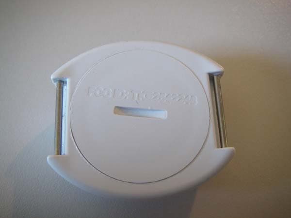
Click to zoom
Application Details
- Equipment Class
- TNT - Licensed Non-Broadcast Transmitter Worn on Body
- Date of Grant
- Jun 07, 2007
- Application Purpose
- Original Equipment
- Date of Application
- Jun 07, 2007
- Equipment Note
- Low POwer Radio
- Frequency Range
- 216.01250000 - 216.98750000
- Company
- H.A.B.I.T. Research Ltd.
- Country
- Canada
Documents & Files
Document Text
Text extracted from the exhibit documents filed with the FCC. Open a document above to read the original.
Users Manual
Project Lifesaver - Client Transmitter Battery change, Maintenance & Daily Testing Project Lifesaver International | phone 757-546-5502 | www.projectlifesaver.org THIS INSTRUCTION PAGE MUST BE INCLUDED WITH ALL TRANSMITTERS SHIPPED TO PROJECT LIFESAVER AGENCIES SUMMARY 1. Client Transmitter Battery Change 2. Transmitter Maintenance 3. Client Transmitter Parts Project Lifesaver - Client Transmitter Battery change, Maintenance & Daily Testing Project Lifesaver International | phone 757-546-5502 | www.projectlifesaver.org 1. Client Transmitter Battery Change 1. Unscrew battery cap (with a coin or screw driver) counter clockwise 2. Complete Transmitter Maintenance (Refer to Instructions on next page) 3. Add the 30 day battery 4. Screw on battery cap clockwise 5. Screw cap on clockwise until it stops and cap is level with transmitter case bottom 5a. Correct Cap position – line up FCC imprinting with edge of Transmitter case 5b. Incorrect Cap Position 7. Insert strap through pins on the bottom Project Lifesaver - Client Transmitter Battery change, Maintenance & Daily Testing Project Lifesaver International | phone 757-546-5502 | www.projectlifesaver.org Transmitter Maintenance The O-ring: ensures that the Project Lifesaver Transmitter remains waterproof. requires the application of Silicone every 30 days, the same time the battery and strap is replaced. Replace the O-ring every six months TIP: Silicone a batch of O-rings before you visit client to do the batter and strap change. WARNING: The O-ring must be replaced every six months 1. Remove the O-ring from the battery cap 2. Use lint-free cloth to clean battery cap threads 3. Apply a small amount of Dow Corning 111 silicone to the O-ring 3. Re-seat the siliconed O-ring back onto the battery cap (note the position) Incorrect position: too high Incorrect position: unevenly seated 4. Use a lint-free cloth to clean screw threads 5. Continue with Client battery and strap change Project Lifesaver - Client Transmitter Battery change, Maintenance & Daily Testing Project Lifesaver International | phone 757-546-5502 | www.projectlifesaver.org FCC COMPLIANCE: The transmitter is authorized by rule under the Low Power Radio Service (47 C.F.R. Part 95) and must not cause harmful interference to TV reception or Federal Government Radar. CAUTION: Any changes or modifications to this device could void the user's authority to operate the equipment. Client Transmitter Parts Silicone O-ring LST-OR $1.00 each Silicone Dow Corning® 111 Silicone Compound Typical Use:Lubrication for control and pressure plug valves, water softener and faucet valves, sealant for vacuum and pressure systems, rubber and plastic O-rings, gaskets and seals. SDC-111 TBA Transmitter battery cap with O-ring LST-BCOR $3.00 each
Cover Letter(s)
692 Sumas Street Victoria, British Columbia V8T 4S6 Canada May 31, 2007 F ederal Communications Commission Authorization and Evaluation Division RE: Confidentiality Request regarding application for certification of FCC ID: TKE50 Pursuant to Sections 0.457 and 0.459 of the Commission’s Rules, we hereby request confidential treatment of information accompanying this application as outlined below: Block Diagram (file name: block diagram2.pdf) Schematics (file name: A158 schematic.pdf) Tune Up Procedure (file name: tuning procedure.pdf) Circuit Description (file name: circuit description.pdf) Parts List (file name: parts list.com) The above materials contain trade secrets and proprietary information not customarily released to the public. The public disclosure of these materials may be harmful to the applicant and provide unjustified benefits to its competitors. Pursuant to DA 04-1705 June 15, 2004 of the Commission’s public notice, we also request temporary confidential treatment of information accompanying this application as outlined below: Internal Photos (file name: internal photos.PDF) Users’ manual (file name: users’ manual.pdf) Sincerely, Jim McIntosh CEO On file
External Photos
EXTERNAL: completed transmitter case
ID Label/Location Info
A) FCC ID and IC label and proposed location Proposed ID number: TKE50 Revised Label location: inside of batter compartment FCC ID: TKE50
ID Label/Location Info
June 6, 2007 Equipment Authorization Division Office of Engineering and Technology Federal Communications Commission Ref: FCC ID: TKE50 Dear Sirs: H.A.B.I.T Research requests acceptance of the labeling proposal described below for transmitters bearing FCC identifier TKE50. The subject transmitters are lower power radio models as shown in figure 1, authorized under 47CFR Part 95G for life saving. Because the majority of the transmitters housing is composed of touching area, and a removable battery pack, there is extremely limited space available to attach the required label carrying the FCC identifier. Attaching the label to the battery pack is not acceptable because the battery pack is a removable item. For this reason, we proposes placing the label carrying the FCC identifier inside the battery compartment as shown in figure 2. The consumer packaging for these models includes the battery pack as a separate item, NOT installed on the radio. As such, the FCC identifier will be readily visible to the user before the battery pack is installed and whenever the battery pack is removed or replaced. In this location, the label will also be protected from physical abuse and remain readable for the anticipated life of the device. FCC ID: TKE50 IC: 6123 A-2542249 The consumer packaging for these models is a "carbon box" which does not allow the transmitters to be seen at time of purchase. In order to meet the requirements of 47CFR Part 2.925 (d), we will add the FCC identifier "TKE50" to the outside of the consumer "carbon box" packaging. Sincerely, Jim McIntosh CEO, President
Internal Photos
B) Internal Photos INTERNAL: Bare board (top) INTERNAL: Bare board (bottom) INTERNAL: Populated Board on transmitter case with top off
Test Report
849 NW STATE ROAD 45 NEWBERRY, FL 32669 USA PH: 888.472.2424 OR 352.472.5500 FAX: 352.472.2030 EMAIL: [email protected] HTTP://WWW.TIMCOENGR.COM FCC PART 95 (G) LOW POWER RADIO SERVICE TEST REPORT APPLICANT H.A.B.I.T Research ADDRESS 692 Sumas St. Victoria, BC V8T 4S6 Canada FCC ID TKE50 MODEL NUMBER 2542249 PRODUCT DESCRIPTION LPRS Transmitter DATE SAMPLE RECEIVED May 9, 2007 DATE TESTED May 15, 2007 TESTED BY Richard Block APPROVED BY Mario de Aranzeta TIMCO REPORT NO. 1099AUT7TestReport.PDF TEST RESULTS PASS FAIL THE ATTACHED REPORT SHALL NOT BE REPRODUCED EXCEPT IN FULL WITHOUT THE WRITTEN APPROVAL OF TIMCO ENGINEERING, INC. Certificate # 0955-01 TABLE OF CONTENTS ATTESTATION STATEMENT...................................................................3 REPORT SUMMARY...............................................................................4 TEST ENVIRONMENT AND TEST SETUP................................................4 DUT DESCRIPTION................................................................................5 TEST EQUIPMENT LIST.........................................................................6 TEST PROCEDURE................................................................................7 TEST RESULT........................................................................................9 RF POWER OUTPUT.................................................................................................. 9 MODULATION CHARACTERISTICS.......................................................................... 10 OCCUPIED BANDWIDTH......................................................................................... 11 SPURIOUS EMISSIONS AT ANTENNA TERMINALS (CONDUCTED).......................... 13 FIELD STRENGTH OF SPURIOUS EMISSIONS (RADIATED)..................................... 14 FREQUENCY STABILITY.......................................................................................... 15 POWER LINE CONDUCTED INTERFERENCE.......................................................... 16 Applicant: H.A.B.I.T Research FCC ID: TKE50 Report: W:\H\HabitResearch\1099AUT7\1099AUT7TestReport.doc Page 2 of 16 ATTESTATION STATEMENT This equipment has been tested in accordance with the standards identified in the referenced test report. To the best of my knowledge and belief, these tests were performed using the measurement procedures described in this report and demonstrate that the equipment complies with the appropriate standards. No modifications were made to the equipment during testing in order to demonstrate compliance with these standards. Certificate #0955-01 All instrumentation and accessories used to test products for compliance to the indicated standards are calibrated regularly in accordance with ISO 17025 requirements. I attest that the necessary measurements were made by me or under my supervision, at Timco Engineering, Inc. located at 849 N.W. State Road 45, Newberry, Florida 32669 USA. Authorized by: Mario de Aranzeta Signature: On File Function: Engineer Date: May 23, 2007 Applicant: H.A.B.I.T Research FCC ID: TKE50 Report: W:\H\HabitResearch\1099AUT7\1099AUT7TestReport.doc Page 3 of 16 REPORT SUMMARY Disclaimer The test results relate only to the items tested. Purpose of Test To show the DUT in compliance with FCC CFR 47, Part 95 (G) requirements for Low Power Radio Test Standards ANSI/TIA 603-C: 2004, FCC CFR 47 Part 95(G), ANSI C63.4: 2003 Related Report(s)/Approval(s) 1099BUT7TestReport.pdf for Pt 15 Subpart B verification 1099CUT7TestReport.pdf for RSS-210 TEST ENVIRONMENT AND TEST SETUP Test Facility All tests were conducted by Timco Engineering Inc. located at 849 NW State Road 45, Newberry, FL 32669 USA Laboratory Test Condition The temperature was 26ºC with a relative humidity of 50%. Deviation from the standards No deviation Modification to the DUT No modification was made. Test Exercise (software etc.) The DUT was placed in continuous transmitting mode of operation. System Setup Stand alone device. Applicant: H.A.B.I.T Research FCC ID: TKE50 Report: W:\H\HabitResearch\1099AUT7\1099AUT7TestReport.doc Page 4 of 16 DUT DESCRIPTION Manufactured by H.A.B.I.T Research Product Description Non-Broadcast Transmitter in the part 95 (G) band using standard channels FCC ID TKE50 M/N 2542249 S/N N/A Max. Output Pwr 0.0001W ERP Emission Designator(s) L1D Modulation on off keying (OOK) Power Source Battery coin cell Test Item Pre-production Type of DUT Portable Antenna Spec permenently attached antenna Calculation of Designator(s) Bn = BK B = 1400 K=5 Bn = 5(1400) = 7000 Applicant: H.A.B.I.T Research FCC ID: TKE50 Report: W:\H\HabitResearch\1099AUT7\1099AUT7TestReport.doc Page 5 of 16 TEST EQUIPMENT LIST (When applicable) Device Manufacturer Model Serial Number Cal/Char Date Due Date Analyzer Tan Tower Spectrum Analyzer HP 8566B Opt 462 3138A07786 3144A20661 CAL 12/7/05 12/7/07 Analyzer Tan Tower RF Preselector HP 85685A 3221A01400 CAL 12/7/05 12/7/07 Analyzer Tan Tower Quasi-Peak Adapter HP 85650A 3303A01690 CAL 12/8/05 12/8/07 Analyzer Tan Tower Preamplifier HP 8449B-H02 3008A00372 CAL 12/8/05 12/8/07 Antenna: Biconnical Electro- Metrics BIA-25 1171 CAL 4/29/05 4/29/07 Antenna: Log-Periodic Electro- Metrics LPA-25 1122 CAL 12/1/06 12/1/08 Antenna: Double- Ridged Horn Electro- Metrics RGA-180 2319 CAL 12/29/04 12/29/06 LISN Electro- Metrics ANS-25/2 2604 CAL 10/5/06 10/5/08 Termaline Wattmeter Bird Electronic Corporation 611 16405 CAL 3/15/07 3/15/09 Applicant: H.A.B.I.T Research FCC ID: TKE50 Report: W:\H\HabitResearch\1099AUT7\1099AUT7TestReport.doc Page 6 of 16 TEST PROCEDURES Power Line Conducted Interference The procedure used was ANSI C63.4-2003 using a 50uH LISN. Both lines were observed with the DUT transmitting. The bandwidth of the spectrum analyzer was 10 kHz with an appropriate sweep speed. RF Power Output The RF power output was measured at the antenna feed point using a peak power meter. A 50-ohm, resistive wattmeter was connected to the RF output conn…
Text truncated - open the document above for the full version.
Contact Information
Applicant
Jim McIntosh(Senior Engineer)
Test Firm
Timco Engineering, Inc.Sid Sanders
Technical Specifications
| # | Rule Parts | Frequency Range | Power Output | Emission | Tolerance |
|---|---|---|---|---|---|
| 1 | 95G | 216.0125 MHz - 216.9875 MHz | 100.00 µW | 7K0L1D | 50.0000000000 ppm |
Other Applications from H.A.B.I.T. Research Ltd.
TKE2542248
Nov 30, 2005Biomedical Telemetry & Locator Transmitter
Equipment Class
DXX - Part 15 Low Power Communication Device Transmitter