TL9NEOSATLITEDigital Satellite Receiver
Cool Sky Co. Ltd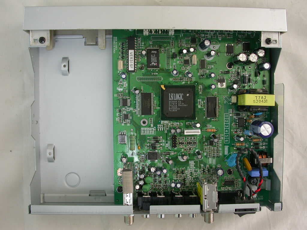
Click to zoom
Application Details
- Equipment Class
- HID - Part 15 TV Interface Device
- Date of Grant
- Nov 14, 2005
- Application Purpose
- Original Equipment
- Date of Application
- Nov 14, 2005
- Equipment Note
- Digital Satellite Receiver
- Frequency Range
- 950.00000000 - 960.00000000
- Company
- Cool Sky Co. Ltd
- Country
- South Korea
Documents & Files
Document Text
Text extracted from the exhibit documents filed with the FCC. Open a document above to read the original.
Users Manual
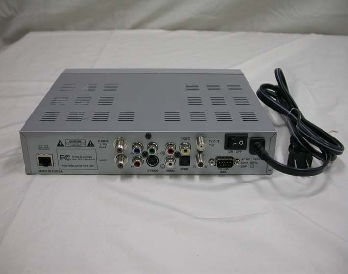
Users Guide DIGITAL SATELLITE RECEIVER Information contained in this manual is subject to change without notice. No part of this publication may be copied, reproduced, or translated to another language for any purpose. FOR YOUR SAFETY Be sure to read the user manual before starting the operation of the receiver. Do not open the housing. The receiver contains high-voltage components and parts. Even after switching off the receiver still contains high-voltage for a while. Do not expose to rain or moisture. Do not make objects or fluid enter the housing through the ventilation slot. If any spilt liquid went into to the housing, unplug the power cord and call your local service provider. Do not place close to any heat source. Do not press with hard or heavy object. To protect possible malfunction by lighting, we recommend you to use power surge unit. Call your local dealer for advise. FOR YOUR SAFETY II For Your Safety 1. Before Getting Started1 1.1 Main Features1 1.2 Accessories2 2. Controls and Functions3 2.1 Front Pannel3 2.2 Rear Pannel4 2.3 Remote Control Unit5 3. Connections7 3.1 Connecting to the TV, VCR and Satellite Antenna7 3.2 Connecting DiSEqC switch7 3.3 Connecting to the TV, HiFi system and SPDIF8 4. Settings and Operations9 4.1 Basic Settings9 4.2 Viewing TV(or Radio)14 4.3 Other functions18 4.4 System Settings21 4.5 Game24 5. Appendix25 5.1 Troubleshooting25 5.2 Specification25 5.3 Glossary26 III CONTENTS 1.1 Main Features Easy Menu Function TV Guide Function RF Output Function Electronic Program Guide(EPG) for On Screen Channel Information Software Upgrading Function Through RS-232C Cable by PC Perfect DiSEqC 1.2 and 0/12V Support for Various Antenna System or 2-LNB on 1 Antenna System Supports of Ku/C band, SCPC and MCPC Additional Audio Output Function for Connection to Hi-Fi Audio System Other Functions of Remote Controller, Receiving Level Selection, Channel Editing, Menu Language Selection and Audio Selection Digital free-to-air Satellite Receiver NTSC & PAL Output Function Regardless of the TV type, NTSC and PAL channels can be viewed by selection When PAL channel is viewed on NTSC TV, small deletion on up & down sides of the screen may occur and it is normal, as its conversion is managed by software. And darker color on the bottom side of the screen may occur, when NTSC channel is viewed on PAL TV. 1200 Transponders and 1820 Channel Memory Function Teletext Supported Multi Language Function(Menu, Audio) BEFORE GETTING STARTED 1 Note 1.2 Accessories RCA cable User’s Guide Batteries(AAA) Remote Control Unit 2 Accessories 2.1 Front pannel STANDBY Turn the power on/off. CHANNEL Change channel, move menu, or input frequency value. CONTROLS AND FUNCTIONS 3 2.2 Rear pannel IF INPUT It receives signals from the LNB in the range of 950 ~ 2150MHz. Connect a satellite dish to DIGITAL. LOOP It sends signal to the another receiver. S-VIdeo It provides high definition screen. AUDIO It provides stereo audio output. Connect the audio on TV to AUDIO with RCA cable. VIDEO It provides composite video output. Connect the Video on TV to VIDEO with RCA cable. SPDIF Output for connection to a digital amplifier TV OUT CH3 It provides a modulated audio and video from the receiver. Connect the TV/VCR on TV to TV/VCR with the RF cable. TV ANT IN The signal supplied to this connector from a TV antenna will be sent to TV antenna output. Connect a TV antenna to TV ANT IN. 0/12 VOLT The 0/12V jack provides 0 or 12V output for external LNB switch. RS-232C DATA It receives data by connecting to PC for software upgrading. Connect with RS-232C cable a PC and receiver. ON/OFF The switch is to turn on or off the main power of the receiver mechanically. 4 Rear pannel 2.3 Remote Control Unit CONTROLS AND FUNCTIONS 5 Open the controller cover on the back and insert two batteries (AAA - 1.5V). EXIT Exit from the menu. Volume Control volume, change item on menu or input frequency value. Channel Change channel, move menu, or input frequency value. POWER Turn the power on/off. TV/SAT Select between TV Channels and Satellite channels for RF output. Numeric(0~9) Changes channel or input frequency value. F. BK It is to move to previous channel. AUDIO Select Stereo, Main or Sub from multi language channels available. CLEAR Clear wrong number input or delete channel from TV (Radio) edit list or favorite channel edit list. MUTE Deactivates current sound. MENU Shows the menu application. Page UP/DOWN Move to previous/next page on TV(Radio) list, Favorite Channels list or Edit TV(Radio) Channels edit list. Scales up & down of video screen. OK Shows channel list. Select menu or value on menu item. INFO Shows the information of current channel. Click the INFO button twice, EPG mode will be displayed. When pressed in channel list channels will be sorted in alphabetical order A-Z. GUIDE Shows EPG[Electronic Program Guide] FAV Add TV or Radio channel to the favorite list on Edit TV(Radio) Channels, or watch favorite channel from your favorite list. SIZE Select between standard 4:3 and wide 16:9 screen sizes. ZOOM 2 times zoom in mode. First press, show target area box. Second press, show zoomed screen. Zoom area can be moved with arrow keys. Exit zoom in mode with "EXIT" remote key. TEXT Change to Teletext mode. LANG Select the audio language from 2 or more audio language channels available. EAST/WEST The function of EAST/WEST button is to move the Position Actuator westward/eastward. TV Change to TV mode from radio channel. RADIO It is for fast change to radio mode from TV channel. 6 Remote Control Unit Connections 7 3.1 Connecting to the TV, VCR and Satellite Antenna It is not necessary to adjust power, as the product is of free - voltage (110~220V ) 1. Connect the RF cable from the TV OUTPUT on the satellite receiver to a TV and connect the RF modulate on the VCR and the TV ANT.IN. 3. Connect an antenna to the LNB socket on the VCR or other receiver and cable of the satellite dish to the DIGITAL on the satellite receiver…
Text truncated - open the document above for the full version.
Users Manual
4.1 Basic Settings If it is the first time using a receiver, you should set parameters for system configuration. Refer to the following section. 1. Turn on your TV and Satellite receiver. 2. Press the MENU button, main menu screen will appear as shown below. <LNB Power> 1. Select Installation on the Main Menu. 2. Select LNB Power. 3. If LNB Power is independently supplied from outside source, set the LNB Power OFF. Otherwise set it ON. 4. After completion of LNB Power setting, go back to Installation menu by pressing MENU. 9 Settings and Operations <DiSEqC 1.2 Limit Settings> If you have a DiSEqC 1.2 motoried system to control your satellite antenna you have to make the following setting. First, you must select ON on DiSEqC 1.2 of LNB Setting in the TP Configuration. < Please refer to the TP Configuration section > 1. Select DiSEqC 1.2 Limit Settings of the installation. 2. You should set the East Limit and West Limit of your satellite antenna If you use the satellite receiver at first. Press OK button on the Change Limit item, set the East/West Limit. 3. Select satellite you want and DiSEqC1.2 Pos. will be set automatically. Satellite / DiSEqC1.2 Pos. The Satellite shows current name of satellite, and DiSEqC1.2 Pos. shows positioner value of the current satellite. DiSEqC1.2 Command DiSEqC1.2 Command changes the current mode between Installer and User. Movement In User mode this is used to tune the position of the motor. In Installer mode this is used 10 Basic Settings to search for the position of a satellite manually. Store Stores the current position of the motor for the selected satellite name. Goto Moves the motor to the stored position of the selected satellite name. <TP Configuration> You have to know valid value for your LNB at first. 1. Select TP Configuration of the installation. 2. Select correct name of Satellite. If there is no proper satellite name listed in the item, select one from any of USER1 ~ USER 19. 3. To change value of LNB from each satellite, press OK button from LNB. < Standard >< Universal > 11 Settings and Operations 4. For universal type of LNB, select Universal from LNB Type item and input the LNB frequency value on Freq.High and Freq.Low by using VOL or numeric key. For standard type of LNB, select Standard from LNB Type and input correct value on Freq.. 5. While only 1 antenna is in use, set the 0/12V switch and DiSEqC mode. to Disable. In case of STANDARD, select OFF from 22KHz. If more then 1 antenna is in use, select 0V or 12V from 0/12V SWITCH, or select a proper position from Mini A, Mini B, DiSEqC 1 ~ DiSEqC 4 by different DiSEqC type as you are using DiSEqC switch. 6. Select Search Channels on the TP Configuration press OK, all the available TP will be searched automatically. 7. Move to desired TP with CH on the RCU. If there are no transponder data which you want, move to Add New TP and press OK button. 8. Select the desired satellite. And input correct values of Frequency, Polarization and Symbol Rate. Select the Polarization value as Hor of Ver. If you did not know accurate polarization value select Auto. You should find the correct data from satellite magazine or internet(http://www.SATCOD 9. After all the values are input, select Search Channels and wait until the automatic search is complete If FTA only is selected as YES, only free channels will be searched without scrambled pay channels. Otherwise all channel with scrambled pay channels will be searched. Scrambled pay channels is marked as $ at the beginning of the channel name. After successful completion of channel searching, move to TV Channels or Radio Channels on MAIN MENU to select currently received channels. Then you should select the TV channel or Radio channel which you want. After then you can watch the TV program or listen to the radio. 12 Basic Settings Note Depending on certain TP or satellite, the Network Search function may not work. 10. To use the Multi Search function, connect the DiSEqC switch or set the DiSEqC 1.2 of Installation. You can search all the channels from the satellites which you select. Select the satellites by FAV button, and press Multi Search. 11. In case of searching a certain satellite which can not be searched by TP Search, add channels by PID. Select Add Channel and input proper Channel name and input the values of Video PID, Audio PID and PCR PID. Then, press OK button from the Add item. [ Network Search ] Network search function is enable to search new TPs and all channels in all TPs. *Network Search : TP Configuration --> Search Channels(Network Search) --> Network Search(Search TP) 13 Settings and Operations Note 4.2 Viewing TV(or Radio) 1. Press the Power button. 2. Press the TV(or Radio) button. 3. If you want to see all TV channel list, click the MENU button and then select the TV Channels(or Radio Channels). TV Channels(or Radio Channels) window will appear. Click the, you will see current Satellite name box. Select any satellite in the satellite name box, only the TV list of selected satellite will be displayed. Viewing Favorite Channel 1. Press FAV key. 2. Select a CH . To move to next or previous page, press PAGE UP/DOWN buttons on Favorite TV(or Radio) List. 14 Viewing TV(or Radio) VOL 15 Edit TV Channels / Edit Radio Channels From these menus you can creat and edit channel list. Press OK button from Edit TV Channels and similar screen will be shown as below. Edit Satellite LIst. You can select your own satellites by creating favorite satellite list. To change the name of satellites, press “INFO” button on RCU. Arrange channel To change the channel orders from TV List, press OK button from your desired channel. Then you should move to desired number by pressing CH , after then press OK button. Its orders will be changed. Delete channel To delete a certain channel from current TV List, press CLEAR button on the channel to be deleted. To confirm the deletion, press CLEAR button once more. To cancel the deletion procedure, press FAV button. Se…
Text truncated - open the document above for the full version.
Users Manual
21 4.4 System Settings Please make sure to press OK button always, after the changing items of System Settings. •Language Setting Select the language which you desire to display on the screen for your system. Press OK button to get in more options. Audio language Only if a current channel contains 2 or more audio language information, set the Audio Language as English or other favorite language. Then press OK button for its confirmation. Menu Language For menu language selection, select desired language from Menu Language of system Settings. Subtitle Mode Subtitle is a printed version of the dialogue, narration, and/or sound effects of a TV program. Subtitle will appear at either the top or bottom of the screen during Subtitle Language Settings and Operations 22 Please select the primary and secondary languages in your area. TV Standard Except for a few, most countires are using PAL system for TV signal, accordingly set TV Standard as PAL. To be more flexible for NTSC or PAL signal from different satellites, select MULTI for automatic signal conversion. Then press OK button for its confirmation. Time Adjustment To set the receiver time for EPG(Electronic Program Guide), set the time according to GMT(Greenwich Mean Time) by using CH . If EPG in England is needed to set, adjust as 00:00. In the case of Beijing, adjust as 08:00. Time Settings Use clock, sleep, on/off Timer function by choosing time settings menu. 1. Press CH buttons or number buttons to set the local time. 2. Set the time STB turns on with on Timer setting menu. 3. Select a channel you wish to see in running the on Timer function. 4. Set the time STB turns off with off Timer setting menu. System Settings 23 TV Aspect Ratio Select 4:3 for normal TV or 16:9 for wide TV. Then press OK button for its confirmation. If 4:3 ratio is selected on normal TV for wide channel, both left and right side of the screen will be a bit trimmed. If 16:9 ratio is selected on normal TV for wide channels the screen trim symptom will not occur. However the screen will be in narrow view. Wide screen will be properly viewed, only when wide channel is broadcasting. Initialization Press OK button from Initialization. If you want initialization, select OK button, otherwise, select any button of remote controller. The receiver will be turned off and on automatically after 1~2 seconds to initialize all the values to factory setting mode. As this procedure will clear and set to factory default values, end users are not recommended to operate this function. Settings and Operations 4.5 Game Select Game on the Main Menu. 1. To play game. Select Game & Press OK. 2. Select play mode by using number buttons & press Exit to Exit. 3. Select the color & press OK. 4. Now play the game. 24 Game 5.1 Troubleshooting 5.2 Specification A p p e n d i x 25 SYMPTOM No picture display and no LED channel display No picture display with normal LED channel display No satellite channel with MAIN MENU screen on No sound with normal screen display Remote control unit does not work LNB/Tuner MPEG VIDEO (CVBS) VIDEO(YPbPr) Video (S-Video) Audio General Data RF input frequency RF input level LNB control LNB power LNB tone switch External LNB switch VIdeo Audio Resolution Video output level Aspect ratio Video output level Video output level Frequency range Sampling frequency Frequency response Audio output level Supply voltage Power consumption Operating temp. Storage temp. Dimensions Weight 950 to 2,150MHz -65 to -25dBm DiSEqC1.0/1.2 13V/18V(Max.400mA) 22KH 2KHz(0.6Vp-p) 0/12V(100mA) MPEG-II Main Profile@Main Level MPEG-II layer I&II 720576 1Vp-p into 75 4:3, 16:9 1Vp-p into 75 Y : 1Vp-p into 75 C : 0.3Vp-p into 75 20Hz to 20KHz 32/44.1/48KHz 20Hz to 20KHz Hi-Fi Quality Digital stereo 2V rms into 600 100~240V (AC, 50/60Hz) Max.25W 0 ~ 50 -40~65 245(W)190(D)50(H)mm 2.8Kg SOLUTION Check the power connection 1. Check the connection with TV 2. Check the connection between TV outside input and receiver cable 1. Check the LNB, Frequency, Polarization and Symbol Rate from Installation menu 2. Check the connection of receiver or Antenna angle 1. Check between sound output connector and TV 2. Check if it is not in MUTE condition Check if the batteries in remote control unit are dead 5.3 Glossary LNB Low Noise Block converter. The LNB is an electronic unit mounted on satellite dish to receive signals reflected by the dish and convert to signals. L.O. frequency Local Oscillator frequency as a part of LNB. It converts the satellite frequency to usable signals for the receiver. Polarization Polarization allows several programs to be fitted into same frequency band. Symbol Rate Size of the digital package transmission Parental Control The function is to allow parents to lock channels for unsuitable viewers. A locked program can only be unlocked with the password. DVB Digital Video Broadcast. International standard for digital TV broadcasting MPEG Moving Picture Experts Group, A system for compression of digital data RF Radio Frequency EPG Electronic Programming Guide. Program information is displayed on the TV screen, depending upon the satellite condition. MHz Abbreviation for MegaHertz. The prefix mega means million, and Hertz means cycles per second. DiSEqC Digital Satellite Equipment Control 26 Glossary NTSC National Television Standards Committee PAL Phase Alternate Line Ku band 11~18GHz Frequency C band 3~4GHz Frequency SCPC Single Channel Per Carrier MCPC Multi Channel Per Carrier PID Packet Identifier. TP TransPonder SCART, RCA A connector for connection of Satellite receiver, VCR and TV sets. VCR Video Cassette Recorder. Appendix 27 Made in Korea MMNAHJS00NE1C00 3D Resources 8210 Lankershim Blvd. Unit #2 North Hollywood CA 91605 Tel : 818-237-5300-1 Fax : 818-237-5305 CAUTION: Changes or modifications not expressly approved by the manufacturer responsible for compliance could void the user’s authority to operate the equipment WARNING This device complies with part 15 of the FCC Rules. Op…
Text truncated - open the document above for the full version.
Cover Letter(s)
FCC ID : TL9NEOSATLITE POWER OF ATTORNEY To whom it may concern: We the undersigned COOL SKY CO.LTD hereby authorize ESTECH Co., Ltd.(EST) of Korea to act on our behalf in all matters relating to all processes required in the FCC Part 15C approval and any communication needed with the national authority. Any and all acts carried out by EST on our behalf shall have the same effects as acts of our own. If you have any questions regarding the authorization, please don’t hesitate to contact us. Sincerely yours, Sign: Wan- Su ,An / Manager Engineer Tel:82-2-6203-0812 Fax: 82-2-6203-0813
Cover Letter(s)
COOL SKY CO.LTD ShinSung Bldg., A-511 #1588-1, Seocho-dong, Seocho-Gu, Seoul,Korea TEL : +82-2-6203-0812 FAX : 82-2-6203-0813 Federal Communications Commission Authorization and Evaluation Division FCC ID : TJ9NEOSATLITE Confidentiality Request Pursuant to Sections 0.457 and 0.459 of the Commission’s Rules, the Applicant hereby requests confidential treatment of information accompanying this Application as outlined below: Schematics Block Diagram The above materials contain trade secrets and proprietary information not customarily released to the public. The public disclosure of these matters might be harmful to the Applicant and provide unjustified benefits to its competitors. The Applicant understands that pursuant to Rule 0.457, disclosure of this Application and all accompanying documentation will not be made before the data of the Grant for this application. Sincerely, Wan-Su, An / Manager Engineer COOL SKY CO.LTD TEL : +82-2-6203-0812 FAX : +82-2-6203-0813
External Photos
1. FRONT 2. REAR 3. INTERNAL
ID Label/Location Info
COOL SKY CO. LTD Digial Satellite Receiver MODEL : NEOSAT LITE FCC ID : TL9NEOSATLITE This device complies with part 15 or rhe FCC Rules. Operation is subject to the dollowing two conditions : (1) This device may not cause harmful interference, and (2) this device must accept ant interference received, including interference that may cause undesired
Internal Photos
INTERNAL PHOTO 1. MAIN 1.1 Front 1.2 Rear
Operational Description
FCC ID TL9NEOSATLITE -Operational description-
Test Report
Compliance Test Report for FCC Company name Address Telephone Product name Model No. Serial No. Test date2005-10-27 ~ Test location Standard □ Class A ■ Class B Test resultOK □ Class A ■ Class B Test resultOK □ Class A □ Class B Test resultOK □ Class A □ Class B Test resultOK □ Class A □ Class B Test resultOK □ Class A □ Class B Test resultOK Tested by Reviewed by Abbreviation * Note - This is certified that the above mentioned producs have been tested for the sample provided by client - No part of this document may be duplicated or reproduced by any means without the express written permission of the Estech Co., Ltd. Digital Satellite Receiver COOL SKY CO. LTD KOREA NEOSAT LITE NONE ■ Antenna Transfer Switch Report Number : ESTF150511-004 , Web : www. estech. co. kr Page 1 of 24 Report NumberESTF150511-004 Manufacturer Country of origin Applicant Product Test item ■ Antenna Conducted Power Measurements ■ Radiated Emission FCC PART 15 (2002) ANSI C 63.4 2003 2005-11-07 ■ Output Terminal Conducted Spurious Emission ■ Output Signal Conducted Level Date of issue2005-11-07 ESTECH. Co., Ltd. 97-1 Hoiuk-Ri Majang-Myon, Icheon-city, KyungKi-Do, Korea ■ Conducted Emission OK, Pass = Passed, Fail = Failed, N/A = not applicable COOL SKY CO. LTD ShinSung Bldg., A-511 #1588-1, Seocho-Dong, Seocho-Gu, Seoul, Korea 82-2-6203-0812 Measurement facility registration number Engineer J.H.Kim Manager Engineer J.M.Yang 94696 (Signature) (Signature) 3 4 5 6 8 8 8 8 8 9 9 9-1 10 10 10 11 12 12 12 13 14 14 14 15 16 16 16 17 18 18 18 19 20 24 A ppendix 1. Spectral diagram A ppendix 2. Phorographs of EUT in side PCB A ppendix 3. Block diagram of EUT A ppendix 4. Circuit Diagram 5.3 Measurement E quipments ........................................................................ 5.5 Test data ................................................................................................ Report Number : ESTF150511-004 , Web : www. estech. co. kr Page 2 of 24 5.4 Environmental conditions ........................................................................ 5.7 Test data ............................................................................................. ... 11. Photographs of test setup ........................................................................... 12. Photographs of EUT .................................................................................... 6. Measurement of conducted disturbance ......................................................... 6.1 Measurement equipment ........................................................................... 6.2 Environmental conditions ........................................................................... 5. Measurement of radiated disturbance ............................................................ 5.2 Radiated Emission(Harminics) .................................................................. Contents 1. Laboratory Information ................................................................................. 2. Description of EUT ....................................................................................... 3. Test Standards ............................................................................................. 4. Measurement condition ................................................................................. 5.1 Radiated Emission .................................................................................... 5.6 Test data(Harminics) .............................................................................. 6.3 Test data ............................................................................................. ... 7. Measurement of antenna conducted power ................................................... 7.1 Measurement e quipment ........................................................................... 7.2 Environmental conditions ........................................................................... 7.3 Test data ................................................................................................ 8. Measurement of output signal conducted level................................................... 8.1 Measurement equipment ........................................................................... 8.2 Environmental conditions ........................................................................... 8.3 Test data ................................................................................................ 9. Measurement of output terminal conducted spurious emission.............................. 9.1 Measurement equipment ........................................................................... 10.2 Environmental conditions ........................................................................ 10.3 Test data ............................................................................................. 9.2 Environmental conditions ........................................................................... 9.3 Test data ................................................................................................ 10. Measurement of antenna transfer switch ......................................................... 10.1 Measurement equipment ........................................................................ 1. Laboratory Information 1.1 General 1.2 Test Lab. Corporation Name : ESTECH Co. Ltd Head Office : Rm 1015, World Venture Center II, 426-5, Gasan-dong, Geumcheon-gu, Seoul, Kor e (Safety & Telecom. Test Lab) EMC Test Lab : 58-1 Osan-Ri, GaNam-Myon, YeoJoo-Gun, KyungKi-Do, Korea 97-1 Hoiuk-Ri Majang-Myon, Icheon-city, KyungKi-Do, Korea 1.3 Official Qualification(s) FCC : Filed Laboratory at Federal Communications Commission This EUT (Equipment Under Test) has been shown to be capable of compliance with the applicable technical standards and is tested in accordance with the measurement procedures as indicated in this report. ESTECH attests to accuracy of test data. All mea…
Text truncated - open the document above for the full version.
Test Setup Photos
1) Setup for Radiated Test : 30 ~ 1000 MHz [ Front ] [ Rear ] Photographs of test setup 2) Setup for Conducted Test : 0.15 ~ 30 MHz [ Front ] [ Rear ] 3) Setup for Antenna conducted power 4) Setup for Output signal conducted level 5) Setup for Output terminal conducted spurious emission 6) Setup for antenna transfer switch
Contact Information
Applicant
An Wan-Su(Senior Engineer)
Technical Contact
ES TechJin Mo Yang
[email protected]82-2-6203-0812
97-1 Hoiuk-Ri Majang-Myon · Icheon-city, KyungKi-Do · South Korea
Test Firm
ESTECH Co., Ltd.Yang Jinmo
Technical Specifications
| # | Rule Parts | Frequency Range | Power Output |
|---|---|---|---|
| 2 | 15B | 950 MHz - 960 MHz | - |
Other Applications from Cool Sky Co. Ltd
TL9PREMIER16
May 05, 2006Satellite Reveiver
Equipment Class
HID - Part 15 TV Interface Device