TMQECB0124588ARemote Control
ELICA S.p.A.
Click to zoom
Application Details
- Equipment Class
- DSC - Part 15 Security/Remote Control Transmitter
- Date of Grant
- Mar 11, 2020
- Application Purpose
- Original Equipment
- Date of Application
- Mar 11, 2020
- Equipment Note
- Remote Control
- Frequency Range
- 433.92000000 - 433.92000000
- Company
- ELICA S.p.A.
- Country
- Italy
Documents & Files
Document Text
Text extracted from the exhibit documents filed with the FCC. Open a document above to read the original.
Users Manual
LEGENDA Tasti A. B. C. D. E. Led ATTENZIONE! Alcune funzioni, qui contrassegnate con ( ̃ ), sono attivabili solo su alcuni modelli di cappa. Fare riferimento al manuale d’uso della propria cappa per maggiori informazioni. ATTENZIONE! Per poter controllare la cappa tramite radiocomando è necessario eseguire la procedura di a liazione (vedi 1 | AFFILIAZIONE). RICARICA DEL RADIOCOMANDO! Collegare il cavetto USB in dotazione al radiocomando e ad un caricabatte- rie con presa USB a 5Volts certificato. Attendere che il LED diventi verde fisso. IN CASO DI MALFUNZIONAMENTO Seguire la procedura di assegnazione nuovo codice (vedi 14 | ASSEGNAZIO- NE NUOVO CODICE). Poi scollegare e ricollegare la cappa alla rete elettrica e ripetere la procedura di a liazione (vedi 1 | AFFILIAZIONE). LEGENDA Led LEGENDA Tipi di pressione sui tasti bianco fisso = trasmissione dati rosso fisso = batteria scarica verde fisso = batteria carica rosso pulsante = in carica > basso livello di energia verde pulsante = in carica > alto livello di energia click click prolungato click simultaneo 1 | AFFILIAZIONE NOTA! Nel caso l’a ̨liazione non sia riuscita scollegare e ricollegare nuovamente la cappa alla rete elettrica e ripetere la procedura di a liazione. Scollegare e ricollegare la cappa alla rete elettrica ed entro il primo minuto premere per 5 secondi i tasti B e E . B + E per 5 s B per 2 s BC 2 | ACCENSIONE CAPPA 3 | INCREMENTO VELOCITÁ 4 | SPEGNIMENTO RITARDATO TEMPORIZZATO (della velocità attuale) (#) 5 | DECREMENTO VELOCITÁ (fino allo spegnimento della cappa) 6 | SPEGNIMENTO CAPPA (#) C per 2 s Premere per 2 secondi il tasto E per iniziare la regolazione intensità luce (direzionata sul piano cottura). Rilasciare il tasto solo quando si è raggiunta la condizione desiderata. E 7 | ACCENSIONE LUCE (direzionata sul piano cottura) 8 | REGOLAZIONE INTENSITÁ LUCE ( direzionata sul piano cottura) (#) 9 | ACCENSIONE LUCE AMBIENTE (#) E > 2 s Premere per 2 secondi il tasto D per iniziare la regolazione intensità luce ambiente. Rilasciare il tasto solo quando si è raggiunta la condizione desiderata. D 10 | REGOLAZIONE INTENSITÁ LUCE A MBIENTE (#) D > 2 s Premere per 2 secondi i tasti D ed E per iniziare la regolazione tono illuminazione. Rilasciare il tasto solo quando si è raggiunta la condizione desiderata. 11 | REGOLAZIONE TONO ILLUMINA- ZIONE (luce calda/luce fredda) (#) D + E > 2 s 12 | ATTIVAZIONE SENSORE (#) A 13 | RESET FILTRI (#) C + E per 2 s A + D + E per 2 s 14 | ASSEGNAZIONE NUOVO CODICE IT EN INFORMAZIONI SULLA SICUREZZA Utilizza il Radiocomando con cura, contiene delicati componenti elettronici. Il Radiocomando può danneggiarsi se fatto cadere, bruciato, perforato o schiacciato o se entra in contatto con sostanze liquide. Non aprire il Radiocomando e non tentare di ripararlo autonomamente. Se disassembli il Radiocomando potresti danneggiarlo. BATTERIA Non tentare di sostituire autonomamen- te la batteria del Radiocomando poiché potresti danneggiarlo. Con la presente Elica dichiara che questo radiocomando è conforme ai requisiti essenziali ed alle altre disposi- zioni pertinenti stabilite dalla direttiva RED 2014/53/EU. La dichiarazione di confor-mità può essere consultata al seguente link: h ttp://elica.com/DeclarationOfConfor- mity.pdf ISTRUZIONI PER UN FUNZIONAMENTO SICURO DEL RADIOCO- MANDO Il Radiocomando può essere utilizzato da bam- bini di età non inferiore a 8 anni e da persone con ridotte capacità fisiche, sensoriali o mentali, o prive di esperienza o della necessaria cono- scenza, purché sotto sorveglianza oppure dopo che le stesse abbia- no ricevuto istruzioni relative all’uso sicuro dell’apparecchio e alla comprensione dei perico- li ad esso inerenti. I bam- bini non devono giocare con il Radiocomando. La pulizia e la manutenzione destinata ad essere e ̋et- tuata dall’utilizzatore non deve essere e ̋ettuata da bambini senza sorve- glianza. White KIT0165599 1 | AFFILIATION NOTE! If a ̨liation is unsuccessful, discon- nect and then reconnect the hood to the power supply and repeat the a liation procedure. Disconnect and then reconnect the hood to the power supply and within the first minute, press keys B and E for 5 seconds. B + E for 5 s B for 2 s BC 2 | HOOD ON 3 | INCREASE SPEED 4 | DELAYED TIMED SHUT-DOWN (of current speed ) (#) 5 | DECREASE SPEED (until hood shuts down) 6 | HOOD OFF (#) C for 2 s Press key E for 2 seconds to start light regulation (directed onto hob). Release the key when the desired lighting condition is achieved. E 7 | LIGHT ON (directed onto hob) 8 | LIGHT REGULATION (directed onto hob) (#) 9 | AMBIENT LIGHT ON (#) E > 2 s Press key D for 2 seconds to start ambient light regulation. Release the key when the desired lighting condition is achieved. D 10 | AMBIENT LIGHT REGULATION (#) D > 2 s Press keys D and E for 2 seconds to start light tone regulation. Release the key when the desired lighting condition is achieved. 11 | LIGHT TONE REGULATION (warm/cold light) (#) D + E > 2 s 12 | SENSOR ACTIVATION (#) A 13 | RESET FILTERS (#) C + E for 2 s A + D + E for 2 s 14 | NEW CODE ALLOCATION KEY Keys A. B. C. D. E. Led KEY Led KEY Key pressing methods white fixed = data transmission red fixed = battery flat green fixed = battery charged red flashing = charging > low power level green flashing = charging > high power level click held click simultaneous click CAUTION! Some functions marked here with an (#) can only be activated on certain hood models. See the operation and maintenance manual of your specific hood for further information CAUTION! To control the hood via remote control, the a liation procedure must be carried out (see 1 | AFFILIATION) RECHARGE THE REMOTE CONTROL! Connect the supplied USB cable to the remote control and to a battery charger with a certified 5V USB port. Wait for the LED to start flashing green IF THERE IS A MALFUNCTION Follow the procedure for a new code allocation (see 14 | NEW CODE ALLOCATION). Then disconnect and reconnect the hood to the power supply an…
Text truncated - open the document above for the full version.
Users Manual
DE FR ES PL PT TR NL DA RU FI XX LEGENDE Tasten A. B. C. D. E. Led EINSCHALTUNG DER ABZUGSHAUBE B 2 | B ERHÖHUNG DER GESCHWINDIGKEIT 3 | Die Abzugshaube vom Stromnetz abtrennen und erneut anschließen und innerhalb der ersten Minute für 5 Sekunden die Tasten B und E drücken. Im Falle, dass der Anschluss nicht erfolgreich war, die Abzugshaube erneut vom Stromnetz abtrennen und anschließen und das Anschlussverfahren wiederholen. B+E ANSCHLUSS1 | EINSCHALTUNG DES UMGEBUNGSLICHTS (#) 9 | D VERZÖGERTES, ZEITABHÄNGIGES ABSCHALTEN (der derzeitigen Geschwindigkeit) (#) B für 2 s drücken 4 | B ABNAHME DER GESCHWINDIGKEIT (bis zum Abschalten der Abzugshaube) 5 | C EINSTELLUNG DER INTENSITÄT DES UMGEBUNGSLICHTS (#) D > 2 s drücken 10 | D EINSTELLUNG DES BELEUCHTUNGSTONS (warmes Licht/kaltes Licht) (#) D + E > 2 s drücken 11 | D+E D+E AKTIVIERUNG SENSOR (#)12 | A RESET FILTER (#) C + E für 2 s drücken 13 | C+E ZUTEILUNG EINES NEUEN CODES_A + D + E für 2 s drücken 14 | A+D+E ABSCHALTUNG DER ABZUGSHAUBE (#)_C für 2 s drücken 6 | C EINSTELLUNG DER LICHTINTENSITÄT (auf die Kochfläche gerichtet) (#) E > 2 s drücken 8 | E EINSCHALTUNG DES LICHTS (auf die Kochfläche gerichtet) 7 | E DeutschDE festes Weiß = Datenübertragung festes Rot = leere Batterie festes Grün = geladene Batterie Taste rot = Laden > niedrige Energiestufe Taste grün = Laden > hohe Energiestufe Click anhaltender Click gleichzeitiger Click LEGENDE: Arten von Druck auf die Tasten LEGENDE: LED LADEN DER FERNBEDIENUNG Das USB-Kabel aus der Ausstattung an die Fernbedienung und an ein zertifiziertes Batterieladegerät mit USB-Anschluss 5 Volts verbinden. Das feste grüne Aufleuchten der LED abwarten IM FALL VON FEHLFUNKTION Die Prozedur der Zuteilung eines neuen Codes ausführen (siehe 14 | ZUTEILUNG EINES NEUEN CODES). Dann die Abzug- shaube vom Stromnetz abtrennen und erneut anschließen und das Anschlussver- fahren wiederholen (siehe 1 | ANSCHLUSS). ACHTUNG! Einige Funktionen, die mit (#) gekennzeich- net sind, können nur bei einigen Modellen von Abzugshaube aktiviert werden. Nehmen Sie für weitere Informationen Bezug auf das Gebrauchshandbuch Ihrer Abzugshaube. FrançaisFR ENCENDIDO CAMPANA B 2 | B INCREMENTO VELOCIDAD3 | Desconecte y vuelva a conectar la campana a la red eléctrica y durante el primer minuto oprima por 5 segundos los botones B y E. En el caso que la afiliación no se haya logrado desconecte y vuelva a conectar nuevamente la campana a la red eléctrica y repita el procedimiento de afiliación. B+E AFILIACIÓN1 | ENCENDIDO LUZ AMBIENTE (#)9 | D APAGADO RETARDADO TEMPORIZADO (de la velocidad actual) (#) Oprima B por 2 s 4 | B DECREMENTO VELOCIDAD (hasta el apagado de la campana) 5 | C REGULACIÓN INTENSIDAD LUZ AMBIENTE (#) Oprima D > 2 s 10 | D REGULACIÓN TONO ILUMINACIÓN (luz caliente/luz fría) (#) Oprima D + E > 2 s 11 | ACTIVACIÓN SENSOR (#)12 | A RESET FILTROS (#) C + E por 2 s 13 | C+E ASIGNACIÓN NUEVO CÓDIGO Oprima A + D + E por 2 s 14 | A+D+E APAGADO CAMPANA (#) Oprima C por 2 s 6 | C REGULACIÓN INTENSIDAD LUZ (dirigida hacia la placa de cocina) (#) Oprima E > 2 s 8 | E ENCENDIDO LUZ (dirigida hacia la placa de cocina) 7 | E EspañolES blanco fijo = transmisión datos rojo fijo = batería descargada verde fijo = batería cargada rojo pulsador = en carga > bajo nivel de energía verde pulsador = en carga > alto nivel de energía click click prolongado click simultáneo LEYENDA: Tipos de presión sobre los botones LEYENDA: LED ¡RECARGA DEL RADIOCOMANDO! Conectar el cablecito USB suministrado con el radiocomando y a un carga baterías con toma USB de 5 Volts certificado. Espere que el LED se vuelva verde fijo EN CASO DE FALLA Siga el procedimiento de asignación de nuevo código (vea 14 | ASIGNACIÓN NUEVO CÓDIGO). Luego desconecte y vuelva a conectar la campana a la red eléctrica y repita el procedimiento de afiliación (vea 1 | AFILIACIÓN). ¡ATENCIÓN! Algunas funciones, aquí señaladas con (#), se pueden activar solo con algunos modelos de campana. Consulte el manual de uso de la propia campana para mayor información. PortuguêsPT branco fixo = transmissão de dados vermelho fixo = bateria descarregada verde fixo = bateria carregada vermelho intermitente = em carga > baixo nível de energia verde intermitente = em carga > alto nível de energia clique clique prolongado clique simultâneo LEGENDA: Tipos de pressão nas teclas LEGENDA: LED CARREGAMENTO DO RADIOCOMANDO! Ligar o cabo USB fornecido ao radioco- mando e a um carregador de bateria com entrada USB de 5 V certificado. Aguardar até que o LED fique verde fixo EM CASO DE AVARIA Seguir o procedimento de atribuição de novo código (ver 14 | ATRIBUIÇÃO DE NOVO CÓDIGO). Depois, desligar e voltar a ligar o exaustor à rede elétrica e repetir o procedimento de associação (ver 1 | ASSOCIAÇÃO). ATENÇÃO! Algumas funções, aqui marcadas com (#), só podem ser ativadas com alguns modelos de exaustor. Consulte o manual de uso do seu exaustor para mais informações. NederlandsNL wit continu aan = datatransmissie rood continu aan = lege batterij groen continu aan = geladen batterij rode knop = aan het laden > laag energieniveau groene knop = aan het laden > hoog energieniveau klik lange klik gelijktijdige klik LEGENDE: Wijze van indrukken van de toetsen LEGENDE: LED OPLADEN VAN DE AFSTANDSBEDIENING! Sluit de meegeleverde USB-kabel aan op de afstandsbediening en een goedgekeurde batterijlader met een 5 Volts USB-aansluiting. Wacht tot de LED continu groen brandt IN GEVAL VAN STORING Volg de procedure voor de toewijzing van een nieuwe code (zie 14 | TOEWIJZING NIEUWE CODE). Ontkoppel de afzuigkap van het elektriciteitsnet en sluit hem vervolgens weer aan (zie 1 | KOPPELING). LET OP! Enkele functies, hier aangegeven met (#), kunnen alleen op sommige modellen van de afzuigkap geactiveerd worden. Raadpleeg de handleiding voor gebruik van uw afzuigkap voor meer informatie. White KIT0165599 D+E ALLUMAGE DE LA HOTTE B 2 | B AUGMENTATION DE LA VITESSE3 | Débrancher puis rebrancher la hotte du réseau électrique et appuyer (da…
Text truncated - open the document above for the full version.
External Photos
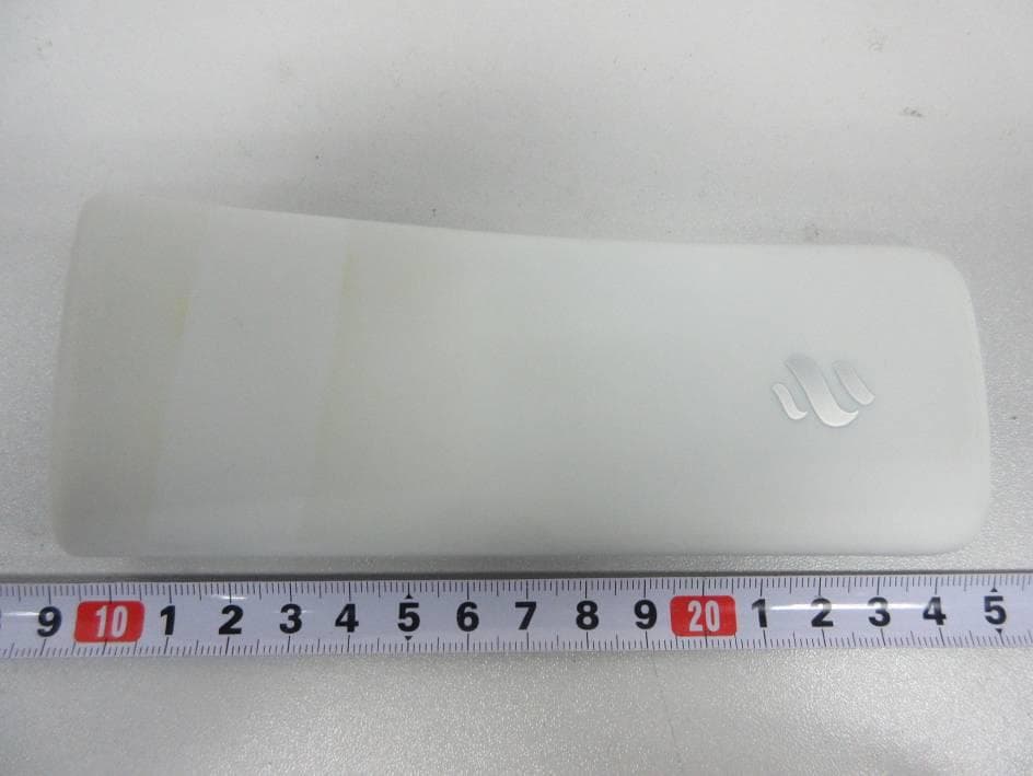
PHOTOGRAPHY OF ECB0124588 REMOTE CONTROL Rev: 0.1 File: ECB0124588_Remote_Control_Ext_Photos_R0.1.docx Pag. 1 di 4 Author: Antonio, Ing. Dimiccoli Date: 06/12/2019 THIS DOCUMENT AND ITS CONTENTS ARE THE EXCLUSIVE PROPERTY OF SELCO INDUSTRY SPA. THEY ARE NOT TO BE COPIED, DISTRIBUTED, OR OTHERWISE DISCLOSED OR USED WITHOUT THE PRIOR WRITTEN CONSENT OF SELCO INDUSTRY SPA. ALL RIGHTS RESERVED ECB0124588 REMOTE CONTROL BLACK: external photography PHOTOGRAPHY OF ECB0124588 REMOTE CONTROL Release: 0.1 File: ECB0124588_Remote_Control_Ext_Photos_R0.1.docx Pag. 2 di 4 THIS DOCUMENT AND ITS CONTENTS ARE THE EXCLUSIVE PROPERTY OF SELCO INDUSTRY SPA. THEY ARE NOT TO BE COPIED, DISTRIBUTED, OR OTHERWISE DISCLOSED OR USED WITHOUT THE PRIOR WRITTEN CONSENT OF SELCO INDUSTRY SPA. ALL RIGHTS RESERVED ECB0124588 REMOTE CONTROL WHITE: external photography PHOTOGRAPHY OF ECB0124588 REMOTE CONTROL Release: 0.1 File: ECB0124588_Remote_Control_Ext_Photos_R0.1.docx Pag. 3 di 4 THIS DOCUMENT AND ITS CONTENTS ARE THE EXCLUSIVE PROPERTY OF SELCO INDUSTRY SPA. THEY ARE NOT TO BE COPIED, DISTRIBUTED, OR OTHERWISE DISCLOSED OR USED WITHOUT THE PRIOR WRITTEN CONSENT OF SELCO INDUSTRY SPA. ALL RIGHTS RESERVED ECB0124588 REMOTE CONTROL WHITE: photography of external lateral side 1: left ECB0124588 REMOTE CONTROL WHITE: photography of external lateral side 2: right PHOTOGRAPHY OF ECB0124588 REMOTE CONTROL Release: 0.1 File: ECB0124588_Remote_Control_Ext_Photos_R0.1.docx Pag. 4 di 4 THIS DOCUMENT AND ITS CONTENTS ARE THE EXCLUSIVE PROPERTY OF SELCO INDUSTRY SPA. THEY ARE NOT TO BE COPIED, DISTRIBUTED, OR OTHERWISE DISCLOSED OR USED WITHOUT THE PRIOR WRITTEN CONSENT OF SELCO INDUSTRY SPA. ALL RIGHTS RESERVED ECB0124588 REMOTE CONTROL WHITE: photography of external lateral side 3: down ECB0124588 REMOTE CONTROL WHITE: photography of external lateral side 4: up
ID Label/Location Info
LABELLING OF ECB0124588 REMOTE CONTROL Rev: 0.1 File: ECB0124588_Remote_Control_Label_R0.1.docx Pag. 1 di 1 Author: Antonio, Ing. Dimiccoli Date: 06/12/2019 THIS DOCUMENT AND ITS CONTENTS ARE THE EXCLUSIVE PROPERTY OF SELCO INDUSTRY SPA. THEY ARE NOT TO BE COPIED, DISTRIBUTED, OR OTHERWISE DISCLOSED OR USED WITHOUT THE PRIOR WRITTEN CONSENT OF SELCO INDUSTRY SPA. ALL RIGHTS RESERVED ECB0124588 REMOTE CONTROL: label
Internal Photos
PHOTOGRAPHY OF ECB0124588 REMOTE CONTROL Rev: 0.1 File: ECB0124588_Remote_Control_Int_Photos_R0.1.docx Pag. 1 di 2 Author: Antonio, Ing. Dimiccoli Date: 06/12/2019 THIS DOCUMENT AND ITS CONTENTS ARE THE EXCLUSIVE PROPERTY OF SELCO INDUSTRY SPA. THEY ARE NOT TO BE COPIED, DISTRIBUTED, OR OTHERWISE DISCLOSED OR USED WITHOUT THE PRIOR WRITTEN CONSENT OF SELCO INDUSTRY SPA. ALL RIGHTS RESERVED ECB0124588 REMOTE CONTROL: internal photography Antenna is integrated on PCB of RF module. It’s highlighted in red in the picture above. PHOTOGRAPHY OF ECB0124588 REMOTE CONTROL Release: 0.2 File: ECB0124588_Remote_Control_Int_Photos_R0.1.docx Pag. 2 di 2 THIS DOCUMENT AND ITS CONTENTS ARE THE EXCLUSIVE PROPERTY OF SELCO INDUSTRY SPA. THEY ARE NOT TO BE COPIED, DISTRIBUTED, OR OTHERWISE DISCLOSED OR USED WITHOUT THE PRIOR WRITTEN CONSENT OF SELCO INDUSTRY SPA. ALL RIGHTS RESERVED ECB0124588 REMOTE CONTROL: internal photography ECB0124588 REMOTE CONTROL: internal photography
Test Report
CMC Centro Misure Compatibilità S.r.l. Via della Fisica, 20 36016 Thiene (VI) – ITALY Tel./Fax +39 0445 367702 www.cmclab.it - [email protected] Independent Testing Laboratory Accredited by ACCREDIA according to UNI CEI EN ISO/IEC 17025 cert. nr. 0168 TRF No. 15-231CMC Page 1 of 57 Test Report No. R19065601 rev.1.0 LAB N° 0168 TEST REPORT Nr. R19065601 Federal Communication Commission (FCC) Report Reference No. ............... : R19065601 Date of issue: .............................. : 29.11.19 Total number pages: ................... : 57 Applicant ́s name ...................... : Elica S.p.A. Address ....................................... : Via Ermanno Casoli, 2 – 60044 Fabriano (AN) – ITALY Test specification: Standards ................................... : FCC Rules & Regulations, Title 47:2018 Part 15 paragraph(s): 203, 204, 207, 209, 215 and 231 Non-standard test method .......... : N/A Test Report Form No. ............... : 15-231CMC Test Report Form(s) Originator .. : CMC Centro Misure Compatibilità S.r.l. Master TRF ................................. : 2019-11 General disclaimer: The test results presented in this report relate only to the object tested. This report shall not be reproduced, except in full, without the written approval of CMC Centro Misure Compatibilità S.r.l. Test item description ................ : Remote Controller for HOOD Trademark .................................. : Elica Manufacturer ............................... : Selco Industry S.p.A. Model / Type reference ............... : ECB0124588 FCC ID ........................................ : TMQECB0124588A Rating(s) ..................................... : 5 Vdc from AC/DC power unit Report Tested by (name + signature) ..... : G. Gandini .............................................................. Approved by (name + signature) .................................... : R. Beghetto .............................................................. CMC Centro Misure Compatibilità S.r.l. Via della Fisica, 20 36016 Thiene (VI) TRF No. 15-231CMC Page 2 of 57 Test Report No. R19065601 rev.1.0 LAB N° 0168 1 Summary 1 Summary ........................................................................................................................................... 2 2 Reference standard .......................................................................................................................... 3 3 List of attachments ............................................................................................................................ 3 4 Deviation(s) from test specification ................................................................................................... 3 5 Testing location ................................................................................................................................. 3 6 General description of test item(s) .................................................................................................... 5 6.1 Photos of the test item ................................................................................................................. 8 7 Verdict summary section .................................................................................................................. 9 8 Test conditions ................................................................................................................................11 8.1 General ......................................................................................................................................11 9 Test results .....................................................................................................................................12 9.1 Antenna requirements ...............................................................................................................12 9.2 Conducted emission ..................................................................................................................13 9.3 Radiated emissions and spurious emissions ............................................................................19 9.4 Fundamental and spurious emissions (≤ 1 GHz) ......................................................................41 9.5 Occupied channel bandwidth ....................................................................................................48 9.6 Periodic operation characteristics ..............................................................................................51 CMC Centro Misure Compatibilità S.r.l. Via della Fisica, 20 36016 Thiene (VI) TRF No. 15-231CMC Page 3 of 57 Test Report No. R19065601 rev.1.0 LAB N° 0168 2 Reference standard FCC Rules and Regulation Title 47 part 15:2018 -- 3 List of attachments Attachment 1: Instruments list, measurement uncertainty, judgement of compliance and quality manual references 4 Deviation(s) from test specification None 5 Testing location CMC Centro Misure Compatibilità S.r.l. Via della Fisica, 20 – 36016 Thiene (VI) – Italy Test site facility’s FCC registration number: 182474 CMC Centro Misure Compatibilità S.r.l. Via della Fisica, 20 36016 Thiene (VI) TRF No. 15-231CMC Page 4 of 57 Test Report No. R19065601 rev.1.0 LAB N° 0168 Testing and sampling: Date of receipt of test item ....................................................... : 15.03.19 Testing start date ..................................................................... : 20.05.19 Testing end date ...................................................................... : 27.11.19 Sampling procedure ................................................................. : Equipment used for testing was picked up by the manufacturer, at the end of the production process with random criterion. The results relate to the sample as it has been received. General remarks: This report shall not be reproduced, except in full, without the written approval of CMC. The test results presented in this report relate only to the obj…
Text truncated - open the document above for the full version.
Test Report
CMC Centro Misure Compatibilità S.r.l. Via della Fisica, 20 36016 Thiene (VI) TRF No. 15-231CMC Page 29 of 57 Test Report No. R19065601 rev.1.0 LAB N° 0168 CMC Centro Misure Compatibilità S.r.l. Via della Fisica, 20 36016 Thiene (VI) TRF No. 15-231CMC Page 30 of 57 Test Report No. R19065601 rev.1.0 LAB N° 0168 CMC Centro Misure Compatibilità S.r.l. Via della Fisica, 20 36016 Thiene (VI) TRF No. 15-231CMC Page 31 of 57 Test Report No. R19065601 rev.1.0 LAB N° 0168 CMC Centro Misure Compatibilità S.r.l. Via della Fisica, 20 36016 Thiene (VI) TRF No. 15-231CMC Page 32 of 57 Test Report No. R19065601 rev.1.0 LAB N° 0168 CMC Centro Misure Compatibilità S.r.l. Via della Fisica, 20 36016 Thiene (VI) TRF No. 15-231CMC Page 33 of 57 Test Report No. R19065601 rev.1.0 LAB N° 0168 CMC Centro Misure Compatibilità S.r.l. Via della Fisica, 20 36016 Thiene (VI) TRF No. 15-231CMC Page 34 of 57 Test Report No. R19065601 rev.1.0 LAB N° 0168 CMC Centro Misure Compatibilità S.r.l. Via della Fisica, 20 36016 Thiene (VI) TRF No. 15-231CMC Page 35 of 57 Test Report No. R19065601 rev.1.0 LAB N° 0168 CMC Centro Misure Compatibilità S.r.l. Via della Fisica, 20 36016 Thiene (VI) TRF No. 15-231CMC Page 36 of 57 Test Report No. R19065601 rev.1.0 LAB N° 0168 CMC Centro Misure Compatibilità S.r.l. Via della Fisica, 20 36016 Thiene (VI) TRF No. 15-231CMC Page 37 of 57 Test Report No. R19065601 rev.1.0 LAB N° 0168 CMC Centro Misure Compatibilità S.r.l. Via della Fisica, 20 36016 Thiene (VI) TRF No. 15-231CMC Page 38 of 57 Test Report No. R19065601 rev.1.0 LAB N° 0168 CMC Centro Misure Compatibilità S.r.l. Via della Fisica, 20 36016 Thiene (VI) TRF No. 15-231CMC Page 39 of 57 Test Report No. R19065601 rev.1.0 LAB N° 0168 CMC Centro Misure Compatibilità S.r.l. Via della Fisica, 20 36016 Thiene (VI) TRF No. 15-231CMC Page 40 of 57 Test Report No. R19065601 rev.1.0 LAB N° 0168 CMC Centro Misure Compatibilità S.r.l. Via della Fisica, 20 36016 Thiene (VI) TRF No. 15-231CMC Page 41 of 57 Test Report No. R19065601 rev.1.0 LAB N° 0168 9.4 Fundamental and spurious emissions (≤ 1 GHz) Tested by .................................... : G. Gandini Test date ..................................... : 22.11.19 Test location (stand) ................... : Semi-anechoic chamber (CMC A070) Reference standards .................. : FCC Rules and Regulation; Titles 47 Part 15.209 and Part 15.231(b) Supplementary test set-up description .................................. : EUT – antenna distance: 3 m Supplementary information ......... : -- Acceptance limits FCC Part 15.231 (b) Fundamental frequency (MHz) Field strength of fundamental [dB(μV/m)] Field strength of spurious emissions [dB(μV/m)] 40,66 to 40,70 67,04 47,04 70 to 130 61,94 41,94 130 to 174 61,94 to 71,48 41,94 to 51,48 174 to 260 71,48 51,48 260 to 470 71,48 to 81,94 51,48 to 61,94 Above 470 81,94 61,94 Test setup Frequency ≤ 1 GHz Test setup PE004_03 Nr. Id. Number Manufacturer Model Description 2 CMC S164 Rohde & Schwarz ESU26 Receiver 20 Hz - 26.5 GHz 1 CMC S287 Schwarzbeck VUSLP 9111B Broadband Antenna CMC Centro Misure Compatibilità S.r.l. Via della Fisica, 20 36016 Thiene (VI) TRF No. 15-231CMC Page 42 of 57 Test Report No. R19065601 rev.1.0 LAB N° 0168 Result – Field strength of fundamental Frequency (MHz) Limits (dBμV/m) Peak level (dBμV/m) Duty cycle correction (dB) Level (dBμV/m) Results 433,92 80,83 90,97 -12,12 78,85 Complies Remarks: EUT was tested in 3 orthogonal planes. The results in this table show the highest value. Duty cycle value has been obtained using the following formula: Duty cycle = 20log0,2478 = -12,12 dB where 0,2478 is the duty cycle declared by the manufacturer Result – Field strength of spurious emissions Frequency (MHz) Limits (dBμV/m) Peak level (dBμV/m) Duty cycle correction (dB) Level (dBμV/m) Results 867,84 60,83 -- -12,12 -- Complies Remarks: EUT was tested in 3 orthogonal planes. The results in this table show the highest value. Duty cycle value has been obtained using the following formula: Duty cycle = 20log0,2478 = -12,12 dB where 0,2478 is the duty cycle declared by the manufacturer CMC Centro Misure Compatibilità S.r.l. Via della Fisica, 20 36016 Thiene (VI) TRF No. 15-231CMC Page 43 of 57 Test Report No. R19065601 rev.1.0 LAB N° 0168 Graphs CMC Centro Misure Compatibilità S.r.l. Via della Fisica, 20 36016 Thiene (VI) TRF No. 15-231CMC Page 44 of 57 Test Report No. R19065601 rev.1.0 LAB N° 0168 CMC Centro Misure Compatibilità S.r.l. Via della Fisica, 20 36016 Thiene (VI) TRF No. 15-231CMC Page 45 of 57 Test Report No. R19065601 rev.1.0 LAB N° 0168 CMC Centro Misure Compatibilità S.r.l. Via della Fisica, 20 36016 Thiene (VI) TRF No. 15-231CMC Page 46 of 57 Test Report No. R19065601 rev.1.0 LAB N° 0168 CMC Centro Misure Compatibilità S.r.l. Via della Fisica, 20 36016 Thiene (VI) TRF No. 15-231CMC Page 47 of 57 Test Report No. R19065601 rev.1.0 LAB N° 0168 CMC Centro Misure Compatibilità S.r.l. Via della Fisica, 20 36016 Thiene (VI) TRF No. 15-231CMC Page 48 of 57 Test Report No. R19065601 rev.1.0 LAB N° 0168 9.5 Occupied channel bandwidth Tested by .................................... : G. Gandini Test date ..................................... : 22.11.19 Test location (stand) ................... : Semi-anechoic chamber (CMC A070) Reference standards .................. : FCC Rules and Regulation; Titles 47 Part 15.231 (c) Test specification ........................ : The bandwidth of the emission shall be no wider than 0,25% of the center frequency for devices operating above 70 MHz and below 900 MHz. For devices operating above 900 MHz, the emission shall be no wider than 0,5% of the center frequency. Bandwidth is determined at the points 20 dB down from the modulated carrier Supplementary information ......... : -- Acceptance limits Devices operating above 70 MHz and below 900 MHz Devices operating above 900 MHz 0,25% of the center frequency 0,5% of the center frequency Test setup Frequency ≤ 1 GHz Test setup PE004_03 Nr. Id. Number Manufactur…
Text truncated - open the document above for the full version.
Test Setup Photos
CMC Centro Misure Compatibilità S.r.l. Via della Fisica, 20 36016 Thiene (VI) – ITALY Tel./Fax +39 0445 367702 www.cmclab.it - [email protected] Independent Testing Laboratory Page 1 of 2 SETUP PHOTO CMC Centro Misure Compatibilità S.r.l. Via della Fisica, 20 36016 Thiene (VI) – ITALY Tel./Fax +39 0445 367702 www.cmclab.it - [email protected] Independent Testing Laboratory Page 2 of 2
Contact Information
Applicant
LUCA DAVID(CERTIFICATION MANAGER)
Test Firm
Dekra Testing and Certification S.r.l.Francesco Marenda
Technical Specifications
| # | Rule Parts | Frequency Range | Power Output |
|---|---|---|---|
| 1 | 15.231 | 433.92 MHz - 433.92 MHz | - |
Other Applications from ELICA S.p.A.
TMQECB0099131
Feb 10, 2015Cooker Hood Remote Control
Equipment Class
DSR - Part 15 Remote Control/Security Device Transceiver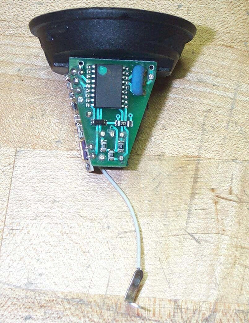
TMQRFT01
Jan 22, 2006Remote control transmitter
Equipment Class
DSC - Part 15 Security/Remote Control Transmitter