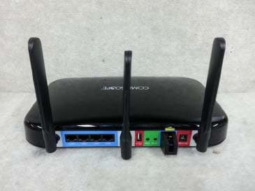
TOU-AIRBRIDGE-APUNII Transmitter
CommScope, Inc. of North Carolina
Click to zoom
Application Details
- Equipment Class
- NII - Unlicensed National Information Infrastructure TX
- Date of Grant
- Nov 09, 2005
- Application Purpose
- Original Equipment
- Date of Application
- Nov 09, 2005
- Equipment Note
- UNII Transmitter
- Frequency Range
- 5802.00000000 - 5820.00000000
- Country
- United States
Documents & Files
Document Text
Text extracted from the exhibit documents filed with the FCC. Open a document above to read the original.
Users Manual
33 P.O. Box 1729 Hickory, NC 28603 Phone: (800) 982-1708 or (828) 324-2200 Fax: (828) 431-2504 (Domestic Sales) Fax: (828) 323-4989 (International Sales) Fax: (828) 328-3400 (Customer Service) Version 2, 19 October 2005 32 Appendix D: Firmware Upgrades The most recent version of firmware may be made available by contacting CommScope. MICROCONTROLLER FIRMWARE UPGRADE To download a new firmware from a computer to the AP microcontroller, it is necessary to have a TFTP client capable of sending a binary file. The parameters to send the firmware are: Target filename: APP Transfer mode: binary (octet) Target port: 70 Block size: 512 Note: The file to be downloaded must be the .bin (binary) image, not the hex version! File size should be 69,376 bytes. ETHERNET CONTROLLER FIRMWARE UPGRADE To download a new firmware from a computer to the AP Ethernet interface controller, it is necessary to have a TFTP client capable of sending a binary file. The parameters to send the firmware are: Target filename: X1 Transfer mode: binary (octet) Target port: 69 Block size: 512 Note: The file to be downloaded must be the .ROM (binary) image, not the hex version! File size should be 32768 or 65536 bytes. 31 C.5 Private IP networks and the Internet If your network is not connected to the Internet and there are no plans to make such a connection, you may use any IP address you wish. However, if you are not connected to the Internet and have plans to connect to the Internet, or you are connected to the Internet and want to operate your SNMP interface on an Intranet, you should use one of the following sub-networks for your network: Class A 10.x.x.x Class B 172.16.x.x Class C 192.168.0.x These network numbers have been reserved for such networks. If you have any questions about IP address assignment ask your Network Administrator. 30 Appendix C: IP Addresses, Netmask, Etc. C.1 IP Addressing An IP address is a 32-bit value, divided into four octets of eight bits each. The standard representation is four decimal numbers (in the range of 0...255), divided by dots. Example: 192.2.1.123. This is called decimal-dot notation. The IP address is divided into two parts: a network and a host part. To support different needs, three “network classes“ have been defined. Depending on the network class, the last one, two or three bytes define the host, while the remaining part defines the network. In the following text, ‘x’ stands for the host part of the IP address: Class A network IP address 1.x.x.x to 127.x.x.x Only 127 different networks of this class exist. These have a very large number of potential connected devices (up to 16777216). Example: 10.0.0.1, (network 10, host 0.0.1) Class B network IP address 128.0.x.x to 191.255.x.x These networks are used for large company networks. Every network can consist of up to 65534 devices. Example: 172.1.3.2 (network 172.1, host 3.2) Class C network IP address 192.0.0.x to 223.255.255.x These network addresses are most common. Most smaller companies’ networks are class C networks. These networks can consist of a maximum number of 254 hosts. Example: 192.7.1.9 (network 192.7.1, host 9) Class D network IP address 224.x.x.x to 239.x.x.x These addresses are used as multicast addresses. Example: 224.7.1.9 (network 224, host 7.1.9) Class E network IP address 240.x.x.x to 254.x.x.x These addresses are reserved. C.2 Network Address An address with all host bits set to "0" is used to address the network as a whole (in routing entries, for example). C.3 Broadcast Address An address with the host part bits all set to “1“ is the broadcast address, meaning “for every station.“ Network and Broadcast addresses must not be used as a host address (e.g. 192.168.0.0 identifies the entire network, 192.168.0.255 identifies the broadcast address). C.4 IP Netmask The netmask is used to divide the IP address differently from the standard defined by the classes A, B, C. By entering a netmask, it is possible to define how many bits from the IP address are to be taken as the network part and how many bits are to be taken as the host part. Standard IP Network Netmask: Class A 8 (network) 24 (host) 255.0.0.0 (mask) Class B 16 (network) 16 (host) 255.255.0.0 (mask) Class C 24 (network) 8 (host) 255.255.255.0 (mask) 29 Appendix B: Setting Auto Mute Threshold The upstream mute threshold is limited by the SNR. At lower levels, the noise level becomes closer to the signal level. Therefore, as the threshold level is dropped, the muting will start to be activated by the noise. This happens closer to the signal level when the signal is lower. The upstream noise level is proportional to the receive gain setting. With a high enough gain and a low enough mute threshold setting, the noise may be high enough to prevent the detection circuitry in the AP from muting. To ensure this does not happen, the threshold should be set no lower than 30 dB below the gain setting (i.e. Gain - 30 dB). So for gains of 36/46/56/66/76 dB, the threshold should be set no lower than 10/16/26/36/46 dBmV. This puts a lower limit on the threshold for a given gain setting. The upper limit of the threshold is based on the upstream signal level. While a setting of 45 dBmV is guaranteed to work with an output level of 45 dBmV, the signal level may change due to CATV plant gain variations. Note that upstream gain variations of the RF link have little effect since the CMTS causes the CM to compensate for upstream gain changes. So it would be recommended to set the threshold at least 3 or 4 dB below the desired output. For example, for a gain of 55 dB and an output level of 35 dBmV, the threshold should be set to between 25 (55 - 30) and 31 dBmV (35 - 4). 28 Appendix A: Specifications AP5800 Specifications DOWNSTREAM Transmit RF frequency band 5799 to 5823 MHz Transmit EIRP +15 to +28 dBm rated maximum IF input frequency range 91 to 857 MHz (channel center frequencies) IF input level range 0 to +20 dBmV per channel Downstream modulation One 6 MHz 64QAM or 25…
Text truncated - open the document above for the full version.
RF Exposure Info
RF Safety Exhibit Revision: 02 Date: 4 November 2005 Equipment: CommScope Airbridge Access Point, model AP5800 FCC ID: TOU-AIRBRIDGE-AP The maximum safe distance from the antenna at which MPE is met or exceeded is calculated from the equation relating field strength in V/m, transmit power in Watts, transmit antenna gain, and separation distance in meters. Basis of calculations: Prediction of MPE limit at a given distance: Equation from page 18 of OET Bulletin 65, Edition 97-01: where: S = power density (mW/cm^2) P = power input to the antenna (mW) G = power gain of the antenna in the direction of interest relative to an isotropic radiator R = distance to the center of radiation of the antenna (cm) Maximum average output power at antenna input terminal: 16.0 (dBm) Maximum average output power at antenna input terminal: 39.81 (mW) Antenna gain (typical): 14 (dBi) Maximum antenna gain: 25.1 (numeric) Prediction distance: 20 (cm) Prediction frequency: 5799-5823 (MHz) MPE limit for uncontrolled exposure at prediction frequency: 1 (mW/cm^2) Power density at prediction frequency: 0.199 (mW/cm^2) Maximum allowable antenna gain: 21.0 (dBi) Margin of Compliance at 20cm = 7.0 (dB) Installation Requirements: The AP5800 is supplied with an integrated antenna. Installation of the AP5800 is described in the user manual, which is supplied with each AP5800. 2 4R PG S π = The following statement is included in the user manual, see “Information to User” section on page 4 of “INSTALLATION AND OPERATION MANUAL”: WARNING: In order to comply with the FCC radio frequency exposure limits of Part 1.1310, this equipment must be installed in such a way as to provide a minimum separation distance of 2 ft. from the transmitting antenna to persons nearby.
RF Exposure Info
Prediction of MPE limit at a given distance Equation from page 18 of OET Bulletin 65, Edition 97-01where: S = power density P = power input to the antennaG = power gain of the antenna in the direction of interest relative to an isotropic radiatorR = distance to the center of radiation of the antenna Maximum peak output power at antenna input terminal: 14.17 (dBm) Maximum peak output power at antenna input terminal: 26.12161354 (mW) Antenna gain(typical): 14 (dBi) Maximum antenna gain: 25.11886432 (numeric) Prediction distance: 20 (cm) Prediction frequency: 5802 (MHz) MPE limit for uncontrolled exposure at prediction frequency: 1 (mW/cm^2) Power density at prediction frequency: 0.130536 (mW/cm^2) Maximum allowable antenna gain: 22.84269855 (dBi) Margin of Compliance: 8.842698554 2 4 R PG S π =
Test Report
FCC Part 15 Subpart E : October 2005 Test Report: 5W53075 Issue 2 Applicant: CommScope, Inc of North Carolina 1100 CommScope Place SE Hickory, North Carolina 28603-1729 Apparatus: CommScope AirBridge Access Point (M/N: AP5800) FCC ID: TOU-AIRBRIDGE-AP In Accordance With: FCC Part 15 Subpart E, 15.407 Unlicensed National Information Infrastructure Devices Tested By: Nemko Canada Inc. 303 River Road Ottawa, Ontario K1V 1H2 Authorized By: Sim Jagpal, Resource Manager Date: 31 October 2005 Total Number of Pages: 32 Nemko Canada Inc. REPORT SUMMARY Report Number: 5W53075 Issue 2 FCC ID: TOU-AIRBRIDGE-AP Specification: FCC Part 15 Subpart E, 15.407 Page 2 of 32 Report Summary These tests were conducted on a sample of the equipment for the purpose of demonstrating compliance with Part 15, Subpart E, 15.407. Radiated tests were conducted in accordance with ANSI C63.4-2003. Radiated emissions are made on an open area test site. A description of the test facility is on file with the FCC. The assessment summary is as follows: Apparatus Assessed: CommScope AirBridge Access Point (M/N: AP5800) Specification: FCC Part 15 Subpart E, 15.407 Compliance Status: Complies Exclusions: None Non-compliances: None Report Release History: Issue 2: Updated product descriptions Author: Jason Nixon, Telecom Specialist Jin Xu, Wireless Specialist Note that the results contained in this report relate only to the items tested and were obtained in the period between the date of initial receipt of samples and the date of issue of the report. This test report has been completed in accordance with the requirements of ISO/IEC 17025. Nemko Canada Inc. authorizes the applicant to reproduce this report provided it is reproduced in its entirety and for use by the company’s employees only. Any use which a third party makes of this report, or any reliance on or decisions to be made based on it, are the responsibility of such third parties. Nemko Canada Inc. accepts no responsibility for damages, if any, suffered by any third party as a result of decisions made or actions based on this report. Nemko Canada Inc. REPORT SUMMARY Report Number: 5W53075 Issue 2 FCC ID: TOU-AIRBRIDGE-AP Specification: FCC Part 15 Subpart E, 15.407 Page 3 of 32 TABLE OF CONTENTS Report Summary......................................................................................................................................... 2 Section 1 : Equipment Under Test............................................................................................................. 4 1.1 Product Identification .................................................................................................................................4 1.2 Samples Submitted for Assessment............................................................................................................4 1.3 Theory of Operation ...................................................................................................................................4 1.4 Technical Specifications of the EUT ..........................................................................................................5 1.5 Block Diagram of the EUT.........................................................................................................................5 Section 2 : Test Conditions......................................................................................................................... 6 2.1 Specifications .............................................................................................................................................6 2.2 Deviations From Laboratory Test Procedures ............................................................................................6 2.3 Test Environment .......................................................................................................................................6 2.4 Test Equipment...........................................................................................................................................6 Section 3 : Observations ............................................................................................................................. 7 3.1 Modifications Performed During Assessment ............................................................................................7 3.2 Record Of Technical Judgements ...............................................................................................................7 3.3 EUT Parameters Affecting Compliance .....................................................................................................7 3.4 Test Deleted................................................................................................................................................7 3.5 Additional Observations .............................................................................................................................7 Section 4 : Results Summary ..................................................................................................................... 8 4.1 FCC Part 15 Subpart E : Test Results.........................................................................................................9 Appendix A : Test Results ........................................................................................................................ 10 Clause 15.209(a) Radiated Emissions within Restricted Bands ..........................................................................10 Clause 15.403(i) Emission Bandwidth ................................................................................................................11 Clause 15.407(a)(3) Power Limits in the 5.725 to 5.825GHz band.....................................................................14 Clause 15.407(b) Spurious Emissions .................................................................................................................2…
Text truncated - open the document above for the full version.
Test Setup Photos
Nemko Canada Inc. APPENDIX B : SETUP PHOTOGRAPHS Report Number: 5W53075 Issue 2 FCC ID: TOU-AIRBRIDGE-AP Specification: FCC Part 15 Subpart E, 15.407 Page 30 of 32 Appendix B : Setup Photographs Spurious Emissions Below 1GHz Setup: Spurious Emissions above 1GHz Setup:
Contact Information
Applicant
Ian Dancel(Applications Engineer)
Technical Contact
Test Firm
Nemko Canada Inc. (Ottawa)Charles Neal
Technical Specifications
| # | Rule Parts | Frequency Range | Power Output |
|---|---|---|---|
| 1 | 15E | 5.80 GHz - 5.82 GHz | 26.00 mW |
Other Applications from CommScope, Inc. of North Carolina
TOUC1004W2
Sep 13, 201510G GEPON ONU
Equipment Class
DTS - Digital Transmission System
TOUONU-1-3-105-D
Aug 05, 2012GE-PON ONT, 802.11 b/g/n Wireless Router
Equipment Class
DTS - Digital Transmission System