TP9BBIIBluetooth Headset
TE-Group NV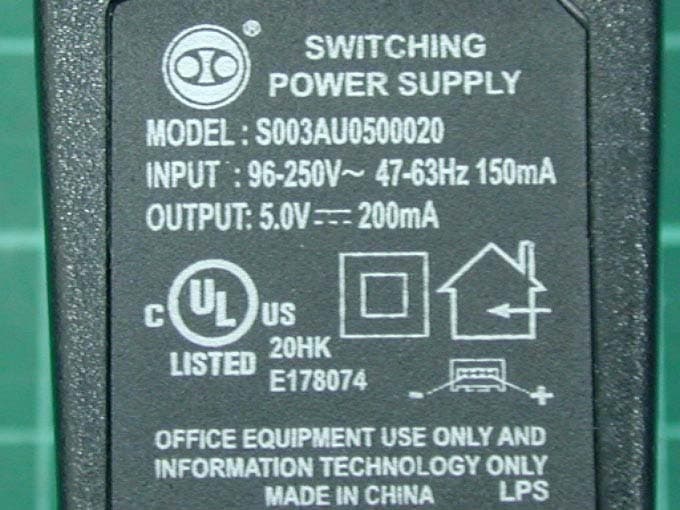
Click to zoom
Application Details
- Equipment Class
- DSS - Part 15 Spread Spectrum Transmitter
- Date of Grant
- Nov 24, 2005
- Application Purpose
- Original Equipment
- Date of Application
- Nov 24, 2005
- Equipment Note
- Bluetooth Headset
- Frequency Range
- 2402.00000000 - 2480.00000000
- Company
- TE-Group NV
- Country
- Belgium
Documents & Files
Document Text
Text extracted from the exhibit documents filed with the FCC. Open a document above to read the original.
Users Manual
Blue Butterfly Bluetooth wireless headset User's manual Safety and General Information Preface Operating Your Headset Electromagnetic Interference/Compatibility Industry Canada Notice to Users Notice to Users What is Bluetooth Wireless Technology? How to Use Your Headset? Headset Features Charging Your Headset Wearing the Headset Turning the Headset On or Off Listening Volume Adjustment Pairing Placing and Receiving Calls Headset Indicator LED Audio Tones General CONTENTS If not use original accessories could be risky and the warranty is void should cause by using original accessories. Do not expose your battery in an environment temperature above +55 deg C(+131 deg F). If the battery is operated in cold temperatures , the battery capacity is reduced. Use your battery in room temperature for maximum battery capacity. The battery can only be charged when the temperature is between +10 deg C(+50 deg F) and +45 deg C (+113 deg F). Additional Information 26 1 4 5 1 2 3 4 4 5 5 7 9 11 12 13 15 19 20 CONTENTS Additional Information Product Care Potentially Explosive Atmospheres Power Supply Emergency Calls Battery Information New Batteries Low Battery Battery use and care The battery is not fully charged when it is new. For first time, please charge for 24 hours before using. When the battery is low, there will be 5 fast beeps every 20 seconds to alert the user. If treated with care, a rechargeable battery has a long service life. A new battery, or one that has not been used for a long period of time, could have reduced capacity the first few times it is used. Note:Only Qualified Service Centers are authorized to remove or replace the battery. Battery Information Additional Information 22 22 23 23 24 25 25 Safety and General Information IMPORTANT INFORMATION ON SAFE AND EFFICIENT OPERATION. READ THIS INFORMATION BEFORE USING THE DEVICE. Note: Facilities Users are not permitted to make changes or modify the device in any way. Changes or modification not expressly approved by the party responsible for compliance could void the user's authority to operate the equipment. See 47 CFR This device complies with part 15 of the FCC Rules. Operation is subject to 2 conditions: (1) This device may not cause harmful interference, and (2) this device must accept any interference received, including interference that may cause undesired operation. See 47 CFR. 15.19(3). Nearly every electronic device is susceptible to electromagnetic interference (EMI) if inadequately shielded, designed, or otherwise configured for electromagnetic compatibility. To avoid electromagnetic interference and/or compatibility conflicts, turn off your device in any facility where posted notices instructed you to do so. Hospitals or health care facilities any be using equipment that is sensitive to external RF energy. Electromagnetic Interference/Compatibility Sec.15.21. 1 Before attempting to clean, please unplug the unit from any power source to avoid potential electric shock. The charger is designed for indoor use only, and must not be used outdoors. Connection cannot be guaranteed at all times under all conditions as the headset used with the electronic device operates using radio signals, landline and cellular networks. Therefore it's not recommended primarily on any electronic device for essential communication (e.g. 911 calls). Keep in mind that when making or receiving calls, the headset and the electronic device connected to it must be turned on and within range. Emergency calls can sometimes be disturbed on certain cellular phone networks or when certain network services and/or phone features are in use. Check with your local cellular service provider for details. Emergency Calls Additional Information Note:For queries about any exceptions when using Bluetooth equipment, due to national requirements or limitations, please visit.www.bluetooth.com IMPORTANT! 24 Safety and General Information Aircraft Medical Devices Hearing Aids Other Medical Devices When instructed to do so, turn off your device when on board an aircraft. Any use of a device must be in accordance with applicable regulations per airline crew instructions. Some devices may interfere with some hearing aids. In the event of such interference, you may want to consult with your hearing aid manufacturer to discuss the alternatives. If you use any other personal medical devices, consult the manufacturer of your device to determine if it is adequately shielded from RF energy. Your physician may be able to assist you in obtaining this information. Operation is subject to the following two conditions: (1) This device may not cause interference and (2) This device must accept any interference, including interference that may cause undesired operation of the device Ref IC RSS 210 Sec. 5.11. The term "IC" : before the certification/ registration number only signifies that registration was performed based on a Industry Canada Notice to Users Declaration of Conformity indicating that Industry Canada technical specifications were met. When surrounded by possible explosive atmosphere, turn off the electronic device as it may generate sparks which can cause an explosion or fire. Explosive atmosphere may include gas stations, fuel or chemical storage facilities, and in environment where metal powders, grain, dust are contained in the air. For safety reasons, do not carry or store flammable goods such as gas, liquid in your vehicle compartment containing an electronic device. Potentially Explosive Atmospheres Power Supply Power supply must be connected to designated power sources as marked on the product. To avoid potential damage to the electric cord, only remove it by grasping onto the AC adaptor rather than the cord itself from the outlet. Ensure the cord is well positioned to avoid potential damage. Additional Information 23 2 Safety and General Information It does not imply that Industry Canada approved the equipment. See Ref IC Self-Making 6(f) and RSP-100 Sec.4. Notice to…
Text truncated - open the document above for the full version.
Cover Letter(s)
APPENDIX B Confidentility Letter (Permanent) Attention: Application Examiner Re: Request for confidentiality Applicant: TE-Group NV FCC ID: TP9BBII To whom it may concern, Request is hereby submitted by TE-Group NV to withhold permanently from public review certain portions of the application for equipment certification for the referenced FCC identifiers. This request for confidentiality is made pursuant to 47 CFR 0.457(d) of the FCC Rules. In particular, the following sections of the application are to be kept permanently confidential: • Schematics • Detailed Block diagrams • Detailed Operational/Functional Description Rationale for request for confidentiality: TE-Group NV has invested considerable time and materials in research and development to produce the referenced product. Disclosure of the permanently confidential portions of this application to competitors would not only give them significant competitive advantages in developing similar products, but would also disclose successful implementation of unpublished, leading edge technology developed by us. If you have questions or need further information, please contact the undersigned. Sincerely, Project Manager TE-Group NV
Cover Letter(s)
APPENDIX A Lettery of Agency "I, an officer of TE-Group NV do hereby authorize Intertek Testing Services to act on our behalf in front of the Federal Communications Commission with respect to all matters relating to certification of equipment under Part 15 and Part 18 of the FCC Rules until further notice." I further certify that no party (as defined in §1.2002(b) of CFR 47, 1992) to this application, including myself, is subject to a denial of federal benefits, that includes FCC benefits, pursuant to Section 5301 of the Anti-Drug Abuse Act of 1988, 21 U.S.C.,853(a). By LIEVE DLFOER Signature Printed Title Project Manager-TE-Group NV
External Photos
Photo 1: External photo of EUT Blue Butterfly II Photo 2: External photo of EUT Blue Butterfly II Photo 3: External photo of Adapter Photo 4: External photo of Adapter Photo 5: External photo of Adapter
ID Label/Location Info
FCC ID Label Location
Internal Photos
Photo 1: Internal photo of EUT Blue Butterfly II Photo 2: Internal photo of EUT Blue Butterfly II Photo 3: Internal photo of EUT Blue Butterfly II Photo 4: Internal photo of EUT Blue Butterfly II
RF Exposure Info
FCC ID.: TP9BBII Report No.: EME-051163 Page 1 of 5 Maximum Permissible Exposure (MPE) Evaluation Report Report No. : EME-051163 Model No. : Blue Butterfly II Issued Date : Nov. 15, 2005 Applicant : TE-Group NV Edward Caertsstraat 39, 2180 Ekeren BELGIUM Test By : Intertek Testing Services Taiwan Ltd. No. 11, Lane 275, Ko-Nan 1 Street, Chia-Tung Li, Shiang-Shan District, Hsinchu City, Taiwan This test report consists of 5 pages in total. It may be duplicated completely for legal use with the allowance of the applicant. It shall not be reproduced except in full, without the written approval of Intertek Laboratory. The test result(s) in this report only applies to the tested sample(s). Kevin Chen Project Engineer Reviewed By Jerry Liu FCC ID.: TP9BBII Report No.: EME-051163 Page 2 of 5 Table of Contents Summary of Tests ............................................................................................................. 3 1. Introduction .................................................................................................................. 4 2. RF Exposure Limit ....................................................................................................... 4 3. RF Exposure calculations ............................................................................................. 5 4. Test results .................................................................................................................... 5 FCC ID.: TP9BBII Report No.: EME-051163 Page 3 of 5 Summary of Tests MPE Evaluation meet FCC OET No. 65: 1997/ IEEE C95.1-1999 Bluetooth Wireless Headset -Model: Blue Butterfly II FCC ID: TP9BBII Test Reference Results MPE Evaluation FCC Guidelines for Human Exposure IEEE C95.1 Complies FCC ID.: TP9BBII Report No.: EME-051163 Page 4 of 5 1. Introduction The EUT operates in the 2.4GHz ISM band. Due to the EUT (include antenna) at its normal operation distance is near by the human body (assume 0.1cm), the EUT was defined as a Portable Device. The reason to do the MPE Evaluation is to avoid the RF hazard to human body. The maximum output power and gain of the antenna were used to calculate the limited distance from the product. The limit for Maximum Permissible Exposure (MPE) specified in FCC 1.1310 is followed. 2. RF Exposure Limit According to FCC 1.1310: The criteria listed in the following table shall be used to evaluate the environmental impact of human exposure to radio-frequency (RF) radiation as specified in 1.1307(b). Limits for Maximum Permissible Exposure (MPE) Frequency Range (MHz) Electric Field Strength (V/m) Magnetic Field Strength (A/m) Power Density (mW/cm 2 ) Average Time (minutes) (A) Limits for Occupational / Control Exposures 30-300 61.4 0.163 1.0 6 300-1500 - - F/300 6 1500-100,000 - - 5 6 (B) Limits for General Population / Uncontrolled Exposure 30-300 27.5 0.073 0.2 30 300-1500 - - F/1500 30 1500-100,000 - - 1.0 30 F= Frequency in MHz FCC ID.: TP9BBII Report No.: EME-051163 Page 5 of 5 3. RF Exposure calculations From §FCC 1.1310 table 1, the maximum permissible RF exposure for an uncontrolled environment is 1mW/(cm 2 ) Power density (S) is calculated by the following formula: S = (P * G)/4πR 2 where, S = Power density (mW/cm 2 ) P = Output power to antenna (mW) R = Distance between radiating structure and observation point (cm) G = Gain of antenna in numeric π = 3.1416 Example: Assume a portable device operates at 2412MHz and its maximum output power is 20mW, and the maximum gain of antenna is 1 (numeric) /0dBi. then the power density (S) = (20 * 1)/4*π*(0.1) 2 = (mW/cm 2 ) 4. Test results Channel Channel Frequency (MHz) Maximum antenna gain (numeric) Output power to antenna (mW) Power density (mW/cm 2 ) Limit of power density (mW/cm 2 ) 1 2402 0.67 1.22 0.000161707 1.0 40 2441 0.67 0.97 0.000128153 1.0 79 2480 0.67 0.76 0.000100863 1.0 The Notice in Installation Manual has been stated as below: While installing and operating this transmitter, the radio frequency exposure limit of 1mW/(cm*cm) may be exceeded at distances close to the transmitter. therefore, the user must maintain a minimum distance of 20 cm from the device at all time.
Test Report
FCC ID. : TP9BBII Report No.: EME-051163 Page 1 of 37 EMC TEST REPORT Report No. : EME-051163 Model No. : Blue Butterfly II Issued Date : Nov. 15, 2005 Applicant : TE-Group NV Edward Caertsstraat 39, 2180 Ekeren BELGIUM Test By : Intertek Testing Services Taiwan Ltd. No. 11, Lane 275, Ko-Nan 1 Street, Chia-Tung Li, Shiang-Shan District, Hsinchu City, Taiwan This test report consists of 37 pages in total. It may be duplicated completely for legal use with the allowance of the applicant. It shall not be reproduced except in full, without the written approval of Intertek Laboratory. The test result(s) in this report only applies to the tested sample(s). Kevin Chen Project Engineer Reviewed By Jerry Liu FCC ID. : TP9BBII Report No.: EME-051163 Page 2 of 37 Table of Contents Summary of Tests ..............................................................................................................4 1. General information ......................................................................................................5 1.1 Identification of the EUT ........................................................................................5 1.2 Additional information about the EUT....................................................................5 1.3 Antenna description.................................................................................................6 2. Test specifications .........................................................................................................7 2.1 Test standard............................................................................................................7 2.2 Operation mode .......................................................................................................7 2.3 Test equipment ........................................................................................................8 3. 20dB Bandwidth test .....................................................................................................9 3.1 Operating environment............................................................................................9 3.2 Test setup & procedure ............................................................................................9 3.3 Measured data of modulated bandwidth test results ...............................................9 3. Carrier Frequency Separation test ...............................................................................11 3.1 Operating environment..........................................................................................11 3.2 Test setup & procedure ..........................................................................................11 3.3 Measured data of Carrier Frequency Separation test result ..................................11 3. Number of hopping frequencies test ...........................................................................13 3.1 Operating environment..........................................................................................13 3.2 Test setup & procedure ..........................................................................................13 3.3 Measured data of number of hopping frequencies test result................................13 3. Time of Occupancy (dwell time) test ..........................................................................15 3.1 Operating environment..........................................................................................15 3.2 Test setup & procedure ..........................................................................................15 4. Maximum Output Power test ......................................................................................19 4.1 Operating environment..........................................................................................19 4.2 Test setup & procedure ..........................................................................................19 4.3 Measured data of Maximum Output Power test results ........................................19 5. Radiated Emission test ................................................................................................20 5.1 Operating environment..........................................................................................20 5.2 Test setup & procedure ..........................................................................................20 5.3 Emission limits ......................................................................................................21 FCC ID. : TP9BBII Report No.: EME-051163 Page 3 of 37 5.4 Radiated spurious emission test data.....................................................................22 5.4.1 Measurement results: frequencies equal to or less than 1 GHz..........................22 5.4.2 Measurement results: frequency above 1GHz ...................................................24 7. Emission on the band edge §FCC 15.247(C) ..............................................................27 7.1 Band-edge (Conducted method)............................................................................28 7.2 Band-edge (Radiated method)...............................................................................30 8. Power Line Conducted Emission test §FCC 15.207 ...................................................34 8.1 Operating environment..........................................................................................34 8.2 Test setup & procedure ..........................................................................................34 8.3 Emission limit .......................................................................................................35 8.4 Uncertainty of Conducted Emission .....................................................................35 8.5 Power Line Conducted Emission test data ............................................................36 FCC ID. : TP9BBII Report No.: EME-051163 Page 4 of 37…
Text truncated - open the document above for the full version.
Test Setup Photos
Photo 1: Conducted Emission Test Set-up photo Blue Butterfly II Photo 2: Conducted Emission Test Set-up photo Blue Butterfly II
Test Setup Photos
Photo 1: Radiated Emission Test set-up photo Charging mode Blue Butterfly II Photo 2: Radiated Emission Test set-up photo Charging mode Blue Butterfly II Photo 3: Radiated Emission Test set-up photo Hopping mode Blue Butterfly II Photo 4: Radiated Emission Test set-up photo Hopping mode Blue Butterfly II
Contact Information
Applicant
Lieve DUFOER(Project manager)
Technical Contact
Interteck Testing services Taiwan Ltd.Kevin Chen
[email protected]+886 3 519 1411
No. 11, Ko-Tze-Nan Chia-Tung Li · Hsinchu · Taiwan
Test Firm
Intertek Testing Services Taiwan Ltd.Alpha Liu
Technical Specifications
| # | Rule Parts | Frequency Range | Power Output |
|---|---|---|---|
| 1 | 15C | 2.40 GHz - 2.48 GHz | 1.20 mW |
Other Applications from TE-Group NV
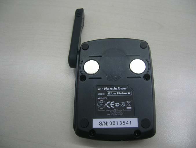
TP9BVII
Jan 20, 2008Bluetooth Carkit
Equipment Class
DSS - Part 15 Spread Spectrum Transmitter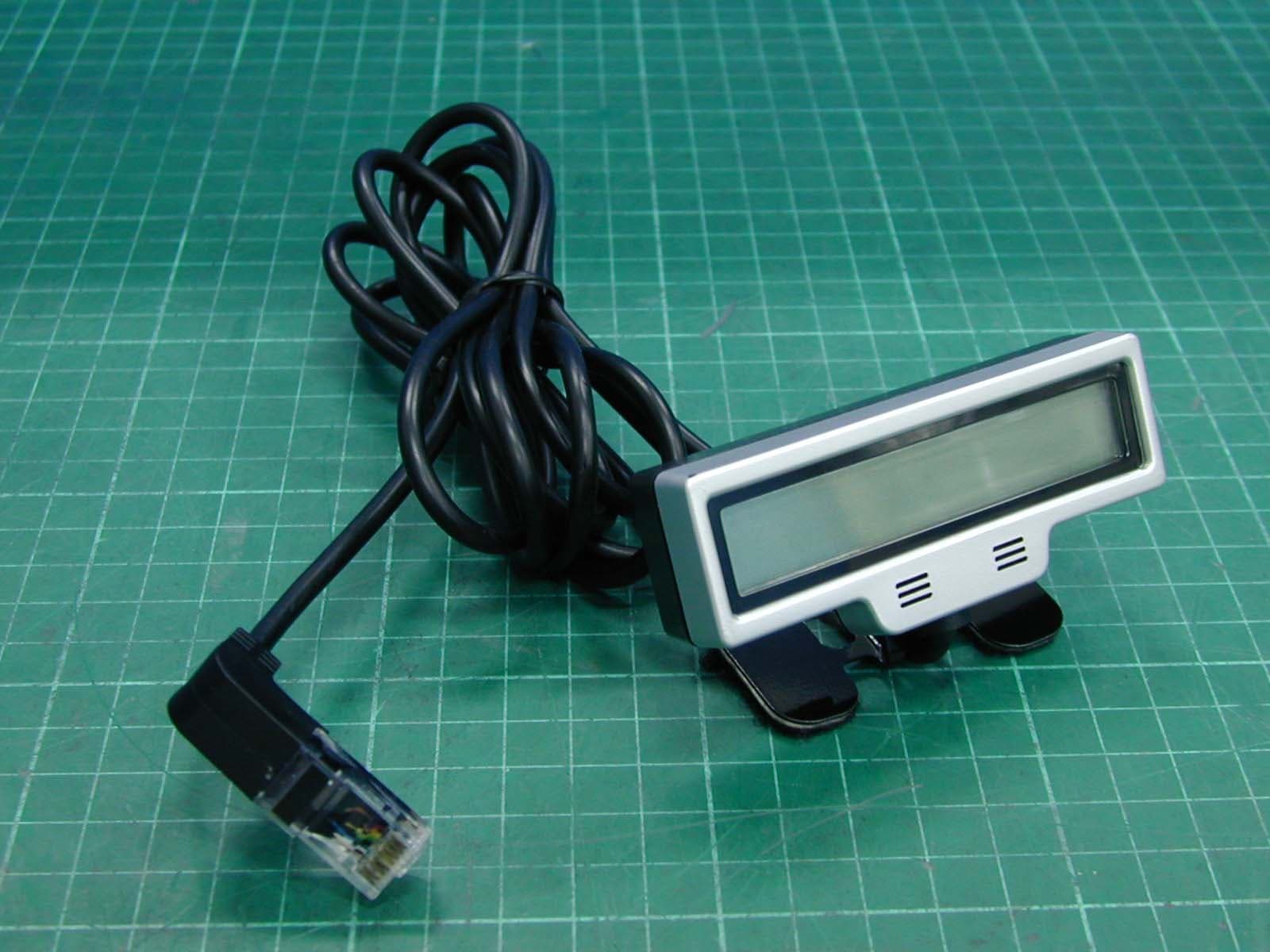
TP9BEII
Aug 01, 2007Bluetooth Car Kit, Blue Eagle II
Equipment Class
DSS - Part 15 Spread Spectrum Transmitter