TP9BEIIBluetooth Car Kit, Blue Eagle II
TE-Group NV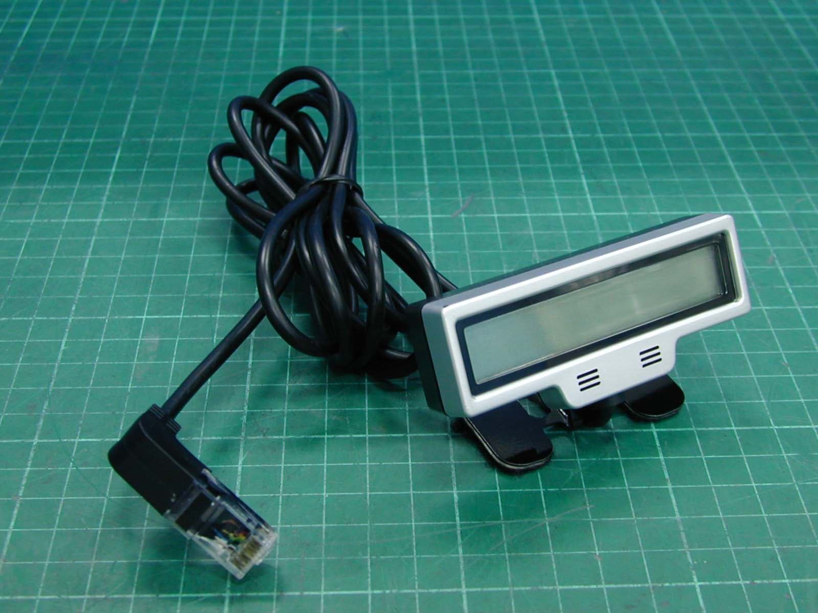
Click to zoom
Application Details
- Equipment Class
- DSS - Part 15 Spread Spectrum Transmitter
- Date of Grant
- Aug 01, 2007
- Application Purpose
- Original Equipment
- Date of Application
- Aug 01, 2007
- Equipment Note
- Bluetooth Car Kit, Blue Eagle II
- Frequency Range
- 2402.00000000 - 2480.00000000
- Company
- TE-Group NV
- Country
- Belgium
Documents & Files
Document Text
Text extracted from the exhibit documents filed with the FCC. Open a document above to read the original.
Users Manual
Advanced Bluetooth Wireless Product BLUE EAGLE II Repaire Center Information]Company name: Mr Handsfree Inc.Address:1738 Rue Des Amarantes, Carignan, J3L 4Z9Quebec, Canada E-nail: [email protected] Advanced Bluetooth Wireless Product IntroductionFeature ListSafety and General InformationBefore UsingLocation of ControlsFunction OperationsPackage contentsTurning the unit onInstalling the unit in a vehiclePairingAdjusting speaker volumeAdjusting ringer volume Contents 1 3 4 6 6 7 9 8 11 11 13 15 24 Troubleshooting Symptom Check & Remedy Nothing appearson LCD display Check that the LCD display is connected to base unit properly.Check that the base unit is connected to cigarette lighter properly. No operation Check that the base unit is connected to cigarette lighter properly.Check that the base unit is turned on.Check the pairing is successful. No LED indicator Check that the base unit is connected to cigarette lighter properly.Check that the base unit is turned on. Restart the unit llllllll Cannot work Disconnect When the carkit and the cell phone have been paired with each other:(1) Please take note carkit turns off automatically when the cigarette lighteris off. Some cigarette lighter turns off when the engine is shut down while someare still on. It depends on the car.(2) On the other hand, some cell phones may be able to connect to carkitautomatically or by pressing the button once after the cell phone is beingturned off and turned on again, or being far away then go back within rangeagain. But some cell phones don't. (In this case, please connect them witheach other manually, for details please refer to your cell phone's manual.) Itdepends on your cell phone. Making a callAnswering a callEnding a callViewing incoming numbersCalling back the last 9 incoming numbersTransferring a callCaller ID System OperationsStatus IndicatorsCare and MaintenanceTroubleshooting 16 17 18 19 19 2020 22 23 24 23 Care and Maintenance Your advanced BLUE EAGLE II is a product of superior design and should be treatedwith care. The suggestions below will help you to enjoy your product for many years. l Keep the product dry. Precipitation, humidity and all types of liquids or moisture cancontain minerals that will corrode electronic circuits.Do not use or store the product in dusty, dirty areas.Do not attempt to open the product. Non-expert handing may damage it.Do not use harsh chemicals, cleaning solvents or strong detergents to clean the product.Use a clean, soft cloth that is slightly damp to clean the product.If the product won't be used for a long time, remove it from cigarette lighter and store itwith safely protected. llll Introduction Your Bluetooth wireless productWhat is Bluetooth wireless technologyThe Bluetooth wireless product is developed for installation in motor vehicles to enble handsfree operation of your mobile phone. It is base on Bluetooth wireless technologyconnects to a compatible phone without wires. It is easily convert your mobile phonecommunication into this in-car solution, talking through its high quality speaker and microphone.The product is intended for use with any mobile phones which support handsfree and(or)headset profile. For the mobile phones which support handsfree and headset profiles, the will try to connect to mobile phone with handsfree profile first, if it fails, then with headset profile.This device complies with Part 15 of the FCC Rules. Operation is subject to the following twoconditions: (1) this device may not cause harmful interference, and (2) this device must acceptany interference received, including interference that may cause undesired operation.Bluetooth wireless technology propels you into a new dimension in connectivity. If your mobile phone and the connects to each other with headset profile, the following function may be invalid.LCD display, Voice dialling, Last number redial and rejecting a call. BLUE EAGLE II BLUE EAGLE II BLUE EAGLE II BLUE EAGLE II 22 1 Status Indicators Status Indicators The Red LED and Blue LED flash alternately. Standby mode The Blue LED flashes every second. Pairing mode In talk mode The Blue LED lights steadly. Introduction What is Bluetooth wireless technology (continued)Bluetooth devices communicate without wires, using built-in radio transceivers that operate on aglobally available radio frequency to ensure worldwide compatibility. Your Bluetooth wirelessproduct can connect to other Bluetooth devices within a range of approximate 10 metres.The wireless connection between the compatible devices established using Bluetoothtechnology is free of charge for the user. In some countries, there may be restrictions on usingBluetooth devices. Check with your local authorities. BLUE EAGLE II 2 21 Caller ID System Operations Transferring a call (continued) 2. Press for about 3 seconds and then a confirmation tone will be heard. Then the call is transferred to mobile phone, and the unit returns to Standby mode. CAUTION:1. To comply with FCC RF exposure compliance requirements, a separation distance of at least 20 cm must be maintained between the antenna of this device and all persons.2. This Transmitter must not be co-located or operating in conjunction with any other antenna or transmitter Feature List 1. Bluetooth compatible2. Up to 10 metres range3. LCD displays calling numbers4. Talk time display5. Full duplex6. Easy installation7. Speaker and ringer volume adjustment8. Call back function9. Voice dialing function10. Transfers a call from the unit to mobile phone 20 3 Caller ID System Operations 1. In Standby mode, press or button repeatedly to select the number youwant to call back. Calling back the last 5 incoming numbers 2. Press once to call back. During a call, the feature allows you to transfer a call from the unit to your mobile phone or viceversa so that you can accept the call in private or in public conveniently. Transferring a call To transfer a call from the unit to mobile phone1. When a call is received, press to an…
Text truncated - open the document above for the full version.
Cover Letter(s)
Confidentiality Letter (Permanent) Attention: Application Examiner Re: Request for confidentiality Applicant: TE-Group NV FCC ID: TP9BEII To whom it may concern, Request is hereby submitted by TE-Group NV to withhold permanently from public review certain portions of the application for equipment certification for the referenced FCC identifiers. This request for confidentiality is made pursuant to 47 CFR 0.457(d) of the FCC Rules. In particular, the following sections of the application are to be kept permanently confidential: [Select one or more of items below, as appropriate] • Schematics • Detailed Block diagrams • Detailed Operational/Functional Description Rationale for request for confidentiality: TE-Group NV has invested considerable time and materials in research and development to produce the referenced product. Disclosure of the permanently confidential portions of this application to competitors would not only give them significant competitive advantages in developing similar products, but would also disclose successful implementation of unpublished, leading edge technology developed by us. If you have questions or need further information, please contact the undersigned. Sincerely, Project Manager TE-Group NV
Cover Letter(s)
Letter of Agency "I, an officer of TE-Group NV do hereby authorize Intertek Testing Services to act on our behalf in front of the Federal Communications Commission with respect to all matters relating to certification of equipment under Part 15 and Part 18 of the FCC Rules until further notice." I further certify that no party (as defined in §1.2002(b) of CFR 47, 1992) to this application, including myself, is subject to a denial of federal benefits, that includes FCC benefits, pursuant to Section 5301 of the Anti-Drug Abuse Act of 1988, 21 U.S.C.,853(a). By LIEVE DLFOER Signature Printed Title Project Manager-TE-Group NV
External Photos
Photo 1: External photo of EUT BLUE EAGLE II Photo 2: External photo of Antenna BLUE EAGLE II Photo 3: External photo of EUT BLUE EAGLE II
ID Label/Location Info
FCC ID Label Location
Internal Photos
Photo 1: Internal photo of EUT BLUE EAGLE II Photo 2: Internal photo of EUT BLUE EAGLE II Photo 3: Internal photo of EUT BLUE EAGLE II Photo 4: Internal photo of EUT BLUE EAGLE II
RF Exposure Info
FCC ID. : TP9BEII Report No.: EME-070289 Page 1 of 5 Maximum Permissible Exposure (MPE) Evaluation Report Report No. : EME-070289 Model No. : BLUE EAGLE II Issued Date : Jul. 19, 2007 Applicant : TE-Group NV Kapelsestraat 61-2950 Kapellen-Belgium Test By : Intertek Testing Services Taiwan Ltd. No. 11, Lane 275, Ko-Nan 1 Street, Chia-Tung Li, Shiang-Shan District, Hsinchu City, Taiwan This test report consists of 6 pages in total. It may be duplicated completely for legal use with the allowance of the applicant. It shall not be reproduced except in full, without the written approval of Intertek Laboratory. The test result(s) in this report only applies to the tested sample(s). Kevin Chen Project Engineer Reviewed By Rico Deng FCC ID. : TP9BEII Report No.: EME-070289 Page 2 of 5 Table of Contents Summary of Tests ............................................................................................................. 3 1. Introduction .................................................................................................................. 4 2. RF Exposure Limit ....................................................................................................... 4 3. RF Exposure calculations ............................................................................................. 5 4. Test results .................................................................................................................... 5 FCC ID. : TP9BEII Report No.: EME-070289 Page 3 of 5 Summary of Tests MPE Evaluation meet FCC OET No. 65: 1997/ IEEE C95.1-1999 Bluetooth Carkit-Model: BLUE EAGLE II FCC ID: TP9BEII Test Reference Results MPE Evaluation FCC Guidelines for Human Exposure IEEE C95.1 Pass FCC ID. : TP9BEII Report No.: EME-070289 Page 4 of 5 1. Introduction The EUT operates in the 2.4GHz ISM band. Due to the EUT (include antenna) at its normal operation distance is at least 20 cm from the human body, the EUT was defined as a Mobile Device. The reason to do the MPE Evaluation is to avoid the RF hazard to human body. The maximum output power and gain of the antenna were used to calculate the limited Power density (S) at 20cm distance away from the product. The limit for Maximum Permissible Exposure (MPE) specified in FCC 1.1310 is followed. According to 1.1307 (b)(1), systems operating under the provisions of this section shall be operated in a manner that ensure that the public is not exposed to radio frequency energy level in excess of the Commission’s guideline. 2. RF Exposure Limit According to FCC 1.1310: The criteria listed in the following table shall be used to evaluate the environmental impact of human exposure to radio-frequency (RF) radiation as specified in 1.1307(b). Limits for Maximum Permissible Exposure (MPE) Frequency Range (MHz) Electric Field Strength (V/m) Magnetic Field Strength (A/m) Power Density (mW/cm 2 ) Average Time (minutes) (A) Limits for Occupational / Control Exposures 30-300 61.4 0.163 1.0 6 300-1500 - - F/300 6 1500-100,000 - - 5 6 (B) Limits for General Population / Uncontrolled Exposure 30-300 27.5 0.073 0.2 30 300-1500 - - F/1500 30 1500-100,000 - - 1.0 30 F= Frequency in MHz FCC ID. : TP9BEII Report No.: EME-070289 Page 5 of 5 3. RF Exposure calculations From FCC 1.1310 table 1, the maximum permissible RF exposure for an uncontrolled environment is 1mW/(cm 2 ) Power density (S) is calculated by the following formula: S = (P * G)/4πR 2 where, S = Power density (mW/cm 2 ) P = Output power to antenna (mW) R = Distance between radiating structure and observation point (cm) G = Gain of antenna in numeric π = 3.1416 Example: Assume a mobile device operates at 2412MHz and its maximum output power is 50mW, and the maximum gain of antenna is 1 (numeric) /0dBi. then the power density (S) = (50 * 1)/4*π*20 2 = 0.00995 (mW/cm 2 ) 4. Test results Channel Channel Frequency (MHz) Maximum antenna gain (numeric) Output power to antenna (mW) Power density (mW/cm 2 ) Limit of power density (mW/cm 2 ) 0 (lowest) 2402 0.67 0.53 0.0000709137 1.0 39 (middle) 2441 0.67 0.71 0.0000945649 1.0 78(highest) 2480 0.67 0.13 0.0000169719 1.0 The Notice in Installation Manual has been stated as below: While installing and operating this transmitter, the radio frequency exposure limit of 1mW/(cm*cm) may be exceeded at distances close to the transmitter. therefore, the user must maintain a minimum distance of 20 cm from the device at all time.
Test Report
FCC ID. : TP9BEII Report No.: EME-070289 Page 1 of 42 EMC TEST REPORT Report No. : EME-070289 Model No. : BLUE EAGLE II Issued Date : Jul. 11, 2007 Applicant: TE-Group NV Kapelsestraat 61-2950 Kapellen-Belgium Test By : Intertek Testing Services Taiwan Ltd. No. 11, Lane 275, Ko-Nan 1 Street, Chia-Tung Li, Shiang-Shan District, Hsinchu City, Taiwan This test report consists of 42 pages in total. It may be duplicated completely for legal use with the allowance of the applicant. It shall not be reproduced except in full, without the written approval of Intertek Laboratory. The test result(s) in this report only applies to the tested sample(s). Kevin Chen Project Engineer Reviewed By Rico Deng FCC ID. : TP9BEII Report No.: EME-070289 Page 2 of 42 Table of Contents Summary of Tests ..............................................................................................................4 1. General information ......................................................................................................5 1.1 Identification of the EUT........................................................................................5 1.2 Additional information about the EUT...................................................................5 1.3 Antenna description ................................................................................................5 1.4 Peripherals equipment ............................................................................................5 2. Test specifications .........................................................................................................6 2.1 Test standard ...........................................................................................................6 2.2 Operation mode ......................................................................................................6 2.3 Test equipment........................................................................................................7 3. 20dB Bandwidth test .....................................................................................................8 3.1 Operating environment ...........................................................................................8 3.2 Test setup & procedure ...........................................................................................8 3.3 Measured data of modulated bandwidth test results...............................................8 4. Carrier Frequency Separation test ...............................................................................12 4.1 Operating environment .........................................................................................12 4.2 Test setup & procedure .........................................................................................12 4.3 Measured data of Carrier Frequency Separation test result..................................12 5. Number of hopping frequencies test ...........................................................................14 5.1 Operating environment .........................................................................................14 5.2 Test setup & procedure .........................................................................................14 5.3 Measured data of number of hopping frequencies test result...............................14 6. Time of Occupancy (dwell time) test ..........................................................................16 6.1 Operating environment .........................................................................................16 6.2 Test setup & procedure .........................................................................................16 7. Maximum Output Power test ......................................................................................20 7.1 Operating environment .........................................................................................20 7.2 Test setup & procedure .........................................................................................20 7.3 Measured data of Maximum Output Power test results .......................................20 8. RF Antenna Conducted Spurious test..........................................................................21 8.1 Operating environment .........................................................................................21 8.2 Test setup & procedure .........................................................................................21 8.3 Measured data of the highest RF Antenna Conducted Spurious test result..........21 9. Radiated Emission test ................................................................................................31 9.1 Operating environment .........................................................................................31 9.2 Test setup & procedure .........................................................................................31 9.3 Emission limits .....................................................................................................33 9.4 Radiated spurious emission test data ....................................................................34 9.4.1 Measurement results: frequencies equal to or less than 1 GHz .........................34 FCC ID. : TP9BEII Report No.: EME-070289 Page 3 of 42 9.4.2 Measurement results: frequency above 1GHz...................................................35 10. Emission on the band edge §FCC 15.247(C) ............................................................38 10.1 Band-edge (Radiated method) ............................................................................39 FCC ID. : TP9BEII Report No.: EME-070289 Page 4 of 42 Summary of Tests Bluetooth Carkit-Model: BLUE EAGLE II FCC ID: TP9BEII Test Reference Results Maximum Output Power test 15.247(b) Pass Carrier Frequency Separation test 15.247(a)(1) Pass Number of hopping frequencies test 15.247(a)(1) Pass Time of Occupancy (dwell…
Text truncated - open the document above for the full version.
Test Setup Photos
Photo 1: Radiated Emission Test set-up photo BLUE EAGLE II Photo 2: Radiated Emission Test set-up photo BLUE EAGLE II
Contact Information
Applicant
Lieve DUFOER(Project manager)
Technical Contact
Intertek Testing Services Taiwan Ltd.Kevin Chen
[email protected]886 3 519 1411 x309
11 ln, Ko Tze Nan, Chia-Tung Li · Hsinchu, · Taiwan
Non-Technical Contact
Intertek Testing Services Taiwan Ltd.Kevin Chen
[email protected]886 3 519 1411 x309
Test Firm
Intertek Testing Services Taiwan Ltd.Alpha Liu
Technical Specifications
| # | Rule Parts | Frequency Range | Power Output |
|---|---|---|---|
| 1 | 15C | 2.40 GHz - 2.48 GHz | 710.00 µW |
Other Applications from TE-Group NV
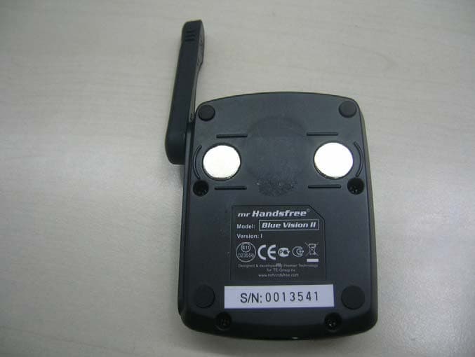
TP9BVII
Jan 20, 2008Bluetooth Carkit
Equipment Class
DSS - Part 15 Spread Spectrum Transmitter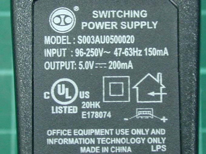
TP9BBII
Nov 24, 2005Bluetooth Headset
Equipment Class
DSS - Part 15 Spread Spectrum Transmitter