TPBMCA8030MCA8030 Booster Amplifier
Union Pacific Corporation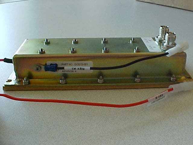
Click to zoom
Application Details
- Equipment Class
- AMP - Amplifier
- Date of Grant
- Sep 19, 2008
- Application Purpose
- Original Equipment
- Date of Application
- Sep 17, 2008
- Equipment Note
- MCA8030 Booster Amplifier
- Frequency Range
- 896.00000000 - 938.00000000
- Company
- Union Pacific Corporation
- Country
- United States
Documents & Files
Document Text
Text extracted from the exhibit documents filed with the FCC. Open a document above to read the original.
Block Diagram
14 15 16 17
Cover Letter(s)
American Telecommunications Certification Body Inc. 6731 Whittier Ave, McLean, VA 22101 March 28, 2008 RE: FCC ID: TPBMCA8030_ATCB005451 Attention: Doug Kramer I have a few comments on this Application. Please note that further comments may arise in response to answers provided to the questions below. 1. Please note that the 731 form is missing information in sections 2a (technical contact info), 4a (description of device), 6 (frequency range, power etc). Please complete the 731 form for the above mentioned fields. 2. Please show the top and bottom of all boards in the internal photos section. 3. Please note that the operational description states that the input and output rf connectors are type N. Please note that the external photos do not appear to show type N connectors. Please verify the connector type or please explain. 4. Please note that the operational description states “More detailed information on the modules in this amplifier can be found in their individual technical descriptions.” However, the other technical descriptions provided are only bill of material and not operational descriptions. Please provide the stated technical descriptions mentioned in the operational description. 5. Please explain table 1 Output power. Please explain what the ‘Correction” factors consists or and how it is used in relation to the ‘Power Uncorrected”. They appear to be added, but nothing is so stated in the report. Please provide the associated formula used to include these two data. 6. Please note that radiated spurious emissions for part 90 devices must be done using the antenna substitution method. Please retest radiated spurious emissions to provide the appropriate ERP antenna substitution data. Please include all pertinent data (i.e. substitution antenna gain, cable loss etc). 7. Please note that as this is an amplifier, intermodulation tests are requried unless the device can only operate on one frequency. Please either confirm the device can only operate on one frequency, or please provide intermodulation test data per TIA603 requirements. 8. Please note that the operational description was not requested to be confidential. IF this exhibit is to be confidential, please include it in the confidentiality request. 9. Please note that based on the response to the above items, further comments may be requried. Dennis Ward mailto:[email protected] The items indicated above must be submitted before processing can continue on the above referenced application. Failure to provide the requested information may result in application termination. Correspondence should be considered part of the permanent submission and may be viewed from the Internet after a Grant of Equipment Authorization is issued. Please do not respond to this correspondence using the email reply button. In order for your response to be processed expeditiously, you must submit your documents through the AmericanTCB.com website. Also, please note that partial responses increase processing time and should not be submitted. Any questions about the content of this correspondence should be directed to the sender.
Cover Letter(s)
Nebraska Center for Excellence in Electronics 4740 Discovery Drive Lincoln, NE 68521-5376 Phone: 402.472.5880 Fax: 402.472.5881 Nebraska Center for Excellence in Electronics 4740 Discovery Drive Lincoln, NE 68521-5376 Phone: 402.472.5880 Fax: 402.472.5881 April 6, 2008 NCEE Labs Response to March 28 ATCB Comments FCC ID: TPBMCA8030_ATCB005451 1. The 731 form has been completed with the missing items that were addressed and the new form has been uploaded. 2. New photos of the bottom of the PCB’s have been uploaded, “Test Photos 2.” 3. The operational description has been modified to state that the EUT uses TNC connectors instead of N connectors. A new operational description has been uploaded, “Operation Description Rev 2.” 4. The operational description has been modified so that it makes no reference to more detailed information on the individual module in the amplifier. A new operational description has been uploaded, “Operation Description Rev 2.” 5. The test report has been modified to give a more clear explanation of the results in table 1. The equations are listed underneath the table. The modified test report has been uploaded “R101306‐01A.” 6. Radiated spurious measurements were done with the antenna substitution method, as stated under the test description in section 3.4. Exploratory measurements were made as described in ANSI C63.4 were used to find frequencies of maximum emissions and the antenna substitution method as described in TIA‐603‐C. Information on antenna gain and cable loss has been added to the results in Table 2. The modified test report has been uploaded “R101306‐01A.” 7. Intermodulation attenuation has been tested per TIA‐603‐C and added to the amended report. 8. Operational description was changed to be confidential per manufacturers’ request. 9. NCEE Labs will provide a response to any further comments based on the previous responses. Nic Johnson Test Engineer NCEE Labs
Operational Description
2 Overall Technical Description Model Series MCA8030 This is a 40% duty amplifier operating in the 896 - 938 MHz frequency band with 30 Watts of output power and is intended for boosting output power from Mobile Transceiver . The amplifier has been designed to work with an Input of 10-15 Watts of RF power from a 14 VDC source. The Input and Ouput connectors are of “Type " TNC"” Female design. The input for the amplifier is obtained from the mobile transceiver while in transmit mode. This input power is amplified 3 to 5 db. There is not a variable power adjust circuit built into this amplifier. It relies upon the input power level to determine the output power level. In no case shall this amplifier produce more than 40 Watts of output power as the transistor is rated at 45 Watts in the designed operational band for this application. The output of the amplifier is directed through a suitable relay for the By-Pass requirement and then through a 9 Pole Low Pass Filter of Chebychev design. Double shielded Teflon cables are used for all high power RF interconnections. An RF sampling circuit is mounted on the Low Pass Filter and provides a DC voltage when the amplifier is operating. This voltage is used to activate a low power relay which activates the RF relay for transmit mode. The normal operation of this unit is in the passive state to allow reception from the antenna, through the MCA, via By Pass relays, to the transceiver.
Test Report
The Nebraska Center for Excellence in Electronics (NCEE) authorizes the above named company to reproduce this report provided it is reproduced in its entirety for use by the company’s employees only. Any use that a third party makes of this report, or any reliance on or decisions made based on it, are the responsibility of such third parties. NCEE accepts no responsibility for damages, if any, suffered by any third party as a result of decisions made or actions based on this report. This report applies only to the items tested. NCEE is a FCC registered lab. Registration #100875 FCC PART 90 EMI MEASUREMENT AND TEST REPORT Company: Union Pacific Corp. 1400 Douglas St. Omaha, NE 68179 Contact: Jeff Massman Product: Union Pacific MCA8030 Booster Amp FCC ID: TPBMCA8030 Test Report No: R101306-01C APPROVED BY: Nic Johnson Test Engineer DATE: 15 September 2008 Total Pages: 29 NCEE Labs R101306-01C FCC ID: TPBMCA8030 IC: 6209A-MCA8030 Page 2 of 29 Table of Contents 1.0 Summary of test results 1.1 Reason for amendment 2.0 EUT Description 2.1 Equipment under test 2.1.1 Identification 2.1.2 EUT received date 2.1.3 EUT tested date 2.1.4 Manufacturer 2.1.5 Serial number 2.2 Testing location 2.3 EUT setup 2.4 Objective 3.0 Test Results 3.1 §2.1046 and §90.205 – RF Output Power 3.2 §2.1049, §90.209, §90.210 – Occupied Bandwidth 3.3 §2.1051 and §90.210 – Spurious Emissions at Antenna Terminals 3.4 §2.1053 and §90.210 – Radiated Spurious Emission Appendix A – Test Photos Appendix B – Output Power Results Appendix C – Occupied Bandwidth Plots Appendix D – Spurious Emissions at Antenna Terminals Plots Appendix E – Radiated Spurious Emissions Results Index of Figures NCEE Labs R101306-01C FCC ID: TPBMCA8030 IC: 6209A-MCA8030 Page 3 of 29 1.0 Summary of test results The equipment under test (EUT) was tested for compliance to FCC Part 90 and Part 2. Below is a summary of the test results. Complete results can be found in Section 3. Rule Description Result § 2.1046 § 90.205 RF Output Power Compliant § 2.1049 § 90.209 § 90.210 Occupied Bandwidth Compliant § 2.1051 § 90.210 Spurious Emissions at Antenna Terminals Compliant § 2.1053 § 90.210 Radiated Spurious Emission Compliant § 90.210 Two-Tone Test N/A § 1.1310 § 2.1091 RF Exposure Compliant TIA-603-C 2.2.16 Intermodulation Attenuation Compliant 1.1 Reason for amendment Amendment B: Table 2 on page 7 was updated to present data on the transmitting antenna and cable correction factors used in the substitution method. More data was taken using previous measurements taken during using a spectrum analyzer and receiving antenna only. The measurements were then matching using a substitution antenna and signal generator and then recorded. The equipment list on page 10 has been modified to show equipment used for testing done on a later date. Amendment C: Corrected margin calculations were made to replace previous. Second data table was deleted because of redundancy. Harmonics data was added to the uplink section of the table. NCEE Labs R101306-01C FCC ID: TPBMCA8030 IC: 6209A-MCA8030 Page 4 of 29 2.0 EUT Description The Equipment Under Test (EUT) was a Union Pacific MCA8030 Booster Amplifier. The MCA8030 is a 40% duty amplifier operating in the 896-938 MHz frequency band with 30W of output power and is intended for boosting the output power from a mobile transceiver. 2.1 Equipment under test 2.1.1 Identification: Union Pacific MCA8030 Booster Amp 2.1.2 EUT received date: 13 Apr 07 2.1.3 EUT tested dates: 13, 16 and 17 April 2007 and 7 May 2007 *12 September 2008 (see section 1.1 for details) 2.1.4 Manufacturer: Union Pacific Corp. 2.1.5 Serial number: NCEE Test 1 (assigned) 2.2 Testing location All testing was performed at the NCEE Labs Lincoln, NE facility, which is an A2LA accredited EMC test laboratory and is registered with the FCC. 2.3 EUT Setup The EUT was powered by an Astron RS-35A power supply (S/N: 200100162). The RF In was connected to the Nexterna G02078-001 radio (S/N: SGF010). The Nexterna Radio was controlled with an external laptop and set to run with maximum transmission. 2.4 Objective This type of report is prepared on behalf of Union Pacific Corporation in accordance with Part 2 and Part 90 of the Federal Communication Commissions rules. The objective of the manufacturer is to determine compliance with FCC rules for output power, occupied bandwidth, spurious emission at antenna terminal, radiated spurious emission, two-tone test and RF exposure. NCEE Labs R101306-01C FCC ID: TPBMCA8030 IC: 6209A-MCA8030 Page 5 of 29 3.0 Test Results NCEE Labs R101306-01C FCC ID: TPBMCA8030 IC: 6209A-MCA8030 Page 6 of 29 3.1 RF Output Power Test: FCC §2.1046 and §90.205 Test Result: Complies Date: 16 Apr 07 Test Description Per FCC §2.1046 and §90.205 The Maximum ERP is dependent upon the station’s antenna HAAT and required service area. The maximum output power of the transmitter for mobile station is 100 watts (20dBW). Test Environment Testing was performed at the NCEE Labs Lincoln facility. Laboratory environmental conditions varied slightly throughout the test: Relative humidity of 40 ± 5% Temperature of 20 ± 2º Celsius Test Setup The RF output of the transceiver was connected to a spectrum analyzer through appropriate attenuators. The spectrum analyzer was used to make power measurements using bandwidth filter large enough to capture the entire bandwidth of the signal. The test setup can be seen in Figures 2 through 4 in appendix A. Test Equipment Used Serial # Manufacturer Model Description Last Cal. 100037 Rohde & Schwarz ESIB26 EMI Test Receiver 8/15/06 N/A JFW 50FH-006-300 6dB Attenuator CNR 9949 BIRD 25-A-MFN-30 30B Attenuator CNR Test Results The power measurements were found to comply with FCC §2.1046 and §90.205. The recorded data can be seen in Table 1 in Appendix B. NCEE Labs R101306-01C FCC ID: TPBMCA8030 IC: 6209A-MCA8030 Page 7 of 29 3.2 Occupied Bandwidth Test: FCC §2.1049, §90.209, §90.210 Test Result: Complies Date: 13 Apr & 7 May 2007 Test Descr…
Text truncated - open the document above for the full version.
Contact Information
Applicant
Dan Rubin(General Director)
Technical Specifications
| # | Rule Parts | Frequency Range | Power Output | Emission | Tolerance |
|---|---|---|---|---|---|
| 1 | 90 | 896 MHz - 938 MHz | 30 W | G7W | Amp |
Other Applications from Union Pacific Corporation

TPBAM090945SF-1H
Dec 21, 2005Booster Amplifier for Portable Tranceiver
Equipment Class
AMP - Amplifier