TQB-WR-01CALLERRemote Control
GRE North America Inc.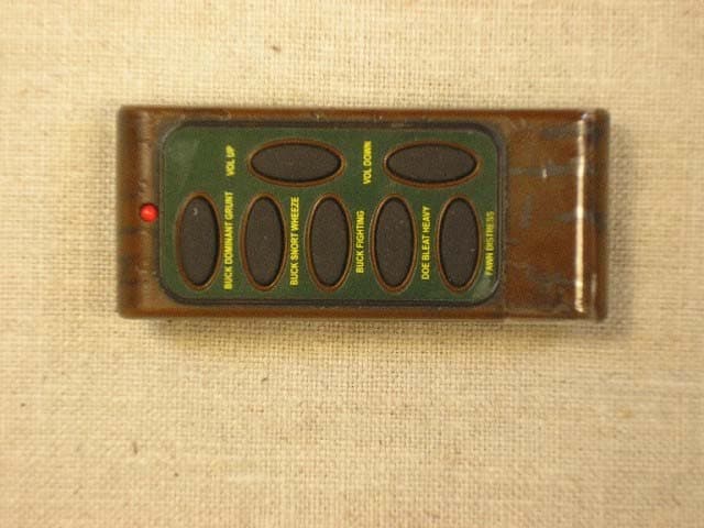
Click to zoom
Application Details
- Equipment Class
- DSR - Part 15 Remote Control/Security Device Transceiver
- Date of Grant
- Jan 29, 2006
- Application Purpose
- Original Equipment
- Date of Application
- Jan 29, 2006
- Equipment Note
- Remote Control
- Frequency Range
- 433.85000000 - 433.85000000
- Company
- GRE North America Inc.
- Country
- United States
Documents & Files
Document Text
Text extracted from the exhibit documents filed with the FCC. Open a document above to read the original.
Users Manual
User's Manual This device complies with Part 15 of the FCC Rules. Operation is subject to the following conditions: (1) This device may not cause harmful interference. (2) This device must accept any interference received, including interference that may cause undesired operation. (3) This device can automatically deactivate the transmitter within not more than 5 seconds of being released. Caution: Any changes or modifications not expressly approved by the party responsible for compliance could void the user's authority to operate the equipment. The Device Data: 1. Model designation: WR-01 2. Power: 12V battery 3. Frequency: 433 MHz Operation instruction: Step: 1. Switch on the call unit by on/off control. 2. Put the call unit away from the remote control unit up to 150 feet 3 Select and push a sound button on the remote control unit. The LED on the remote control will light indicating that the remote control is working when a button is pushed. The remote control will not work if two or more buttons are pushed at the same time. 4 The call unit will sound when the button on the remote control unit is pushed. Once the button is released the sound will not stop until the sound cycle ends. 5 The volume of the control unit is controlled by the “Vol Up” and “Vol Down” buttons on the remote control unit. The LED light will light to show that the remote control unit is working when a button is pushed 6 When finished using the remote control unit, do not forget to turn the call unit off . NOTE: This equipment has been tested and found to comply with the limits for a Class B digital device, pursuant to part 15 of the FCC Rules. These limits are designed to provide reasonable protection against harmful interference in a residential installation. This equipment generates, uses and can radiate radio frequency energy and, if not installed and used in accordance with the instructions, may cause harmful interference to radio communications. However, there is no guarantee that interference will not occur in a particular installation. If this equipment does cause harmful interference to radio or television reception, which can be determined by turning the equipment off and on, the user is encouraged to try to correct the interference by one or more of the following measures: —Reorient or relocate the receiving antenna. —Increase the separation between the equipment and receiver. —Connect the equipment into an outlet on a circuit different from that to which the receiver is connected. —Consult the dealer or an experienced radio/TV technician for help.
Test Report
EMC Report for «Company» on the «EutModelNo» FCC Part 15.231 File: «ReportNo» FCC ID: «FCCID» «AutoMergeField» Page 1 of 16 TEST REPORT Report Number: 3084244-37-1-1 Project Number: 3084244 January 20, 2006 Testing performed on the WR Predator Model Number: WR-01 to FCC Part 15.231 For GRE North America Test Performed by: Test Authorized by: Intertek ETL Semko 1950 Evergreen Blvd, Suite 100 Duluth, GA 30096 GRE North America 3030 McEver Road, Bldg. 1, Suite 100 Gainsville, GA 30504 Prepared by: Date: 1/20/2006 Chris Capelle, Associate Engineer Reviewed by: Date: 1/20/2006 Jeremy Pickens, EMC Team Leader All services undertaken are subject to the following general policy: This report is for the exclusive use of Intertek's Client and is provided pursuant to the agreement between Intertek and its Client. Intertek's responsibility and liability are limited to the terms and conditions of the agreement. Intertek assumes no liability to any party, other than to the Client in accordance with the agreement, for any loss, expense or damage occasioned by the use of this report. Only the Client is authorized to copy or distribute this report and then only in its entirety. Any use of the Intertek name or one of its marks for the sale or advertisement of the tested material, product or service must first be approved in writing by Intertek. The observations and test results in this report are relevant only to the sample tested. This report by itself does not imply that the material, product, or service is or has ever been under an Intertek certification program. This report must not be used to claim product endorsement by A2LA, NIST, or any agency of the US Government. Intertek EMC Report for «Company»on the «EutModelNo» FCC Part 15.231 File: «ReportNo» FCC ID: «FCCID» «AutoMergeField» Page 2 of 16 TABLE OF CONTENTS 1Summary of Tests ......................................................................................................................... 3 2General Description ...................................................................................................................... 4 2.1Product Description ........................................................................................................... 4 2.2Related Submittal(s) Grants ............................................................................................... 4 2.3Test Methodology .............................................................................................................. 4 2.4Test Facility ....................................................................................................................... 5 3System Test Configuration........................................................................................................... 5 3.1Support Equipment ............................................................................................................5 3.2Cabling............................................................................................................................... 5 3.3Block Diagram of Test Setup............................................................................................. 5 3.4Justification ........................................................................................................................ 6 3.5Software Exercise Program................................................................................................ 6 3.6Mode of Operation during Test ......................................................................................... 6 3.7Modifications Required for Compliance ........................................................................... 6 3.8Additions, deviations and exclusions from standards ........................................................ 6 4Measurement Results.................................................................................................................... 7 4.1Radiated Emission ............................................................................................................. 7 4.1.1Procedure .............................................................................................................. 7 4.1.2Field Strength Calculation .................................................................................... 7 4.1.3Test Result ............................................................................................................ 8 4.2AC Line Conducted Emission ........................................................................................... 9 4.2.1Measurement Procedure........................................................................................ 9 4.2.2Test Result ............................................................................................................ 9 4.3Occupied Bandwidth Plot .................................................................................................. 10 4.4Transmitter Duty Cycle Calculation and Measurements ................................................... 11 5Antenna Requirement .................................................................................................................. 15 6List of test equipment ................................................................................................................... 16 7Document History ......................................................................................................................... 16 INDEX OF FIGURES Figure 4-1: Bandwidth plot ......................................................................................................................... 10 Figure 4-2: Output – Pulse ON Width ........................................................................................................ 11 Figure 4-3: Output – Pulse ON Cycle Width .............................................................................................. 12 Figure 4-4: Output – Pulse Sequence Width.................…
Text truncated - open the document above for the full version.
Contact Information
Applicant
Tim Hall(Manager, Sales/Technology)
Technical Contact
IntertekChris D Capelle
[email protected]678-775-2400
1950 Evergreen Blvd · Duluth, Georgia · United States
Test Firm
Intertek Testing Services NA Inc.Charles Parker
Technical Specifications
| # | Rule Parts | Frequency Range | Power Output |
|---|---|---|---|
| 1 | 15.231 | 433.85 MHz - 433.85 MHz | - |
Other Applications from GRE North America Inc.
TQB-PREDATION
Jul 26, 2007Remote Control
Equipment Class
DSC - Part 15 Security/Remote Control Transmitter