TQMWIRINT01MOTOR WIRELESS INTERCOM
Best Talent Industrial Limited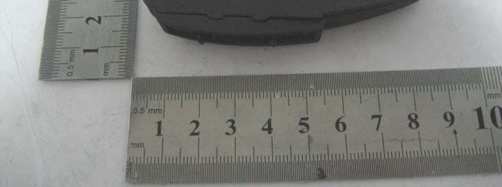
Click to zoom
Application Details
- Equipment Class
- DSS - Part 15 Spread Spectrum Transmitter
- Date of Grant
- Jun 23, 2010
- Application Purpose
- Original Equipment
- Date of Application
- Jun 23, 2010
- Equipment Note
- MOTOR WIRELESS INTERCOM
- Frequency Range
- 2402.00000000 - 2480.00000000
- Country
- China
Documents & Files
Document Text
Text extracted from the exhibit documents filed with the FCC. Open a document above to read the original.
Users Manual
-4- JH-BM837 四、Interphone conversation: To wear helmet, the driver and passenger can hear the voice with each other. Press VOC+VOC- button without grade to adjust volume control for long time. 五、If any person of driver's headset or passenger's headset is far way effective distance 10M, the driver's headset and passenter will search each other 5minutes. If they come back to effective distance within 5minutes, the conversation will be reversed connectting. 六、Switch off: Separetely press intercom/on/off button for driver's headset and passenger's headset,after 3s, the system will switch off. If one person switch off or away from effective distance, the other side will step into power off automatically within 5minutes. 七、Bluetooth conversation and operation: Login for bluetooth device: press talk button for driver's headset, after 5s, the red indicator for driver's headset flicker quickly. It indicates that the bluetooth login is successful. Meanwhile switch on seach manue for bluetooth mobilephone and other device, search BM837, confirm to connectting after entering password 0000, the device will display connecting successfully. The red indicator for driver's headphone flicker slowly. It means that the bluetooth login suc- cessfully and step into standby mode. When the the call is coming, pls press talk button for device's headset and answer. After answering, pls press Talk button of driver's headphone or off button of bluetooth mobile. Motor headset is one helmet one for motorycylce user we design. Using this product,easy to achieve communication for driver and passenger. The helmet headset has bluetooth function, motorcycle driver can real- ization voice phone function by connecting helmet headset with bluetooth mobile phone. It is communication tool to provide safety and convient for motorcycle user. Especially it is suitable for policemen patrol, racing and motorcycle tour and so on. Best Talent develop new wireless intercom has good conversation quality and low power function, best choice for profes- sional purchaser. 1.Earphone installed on motorcycle helmet, more safety and convient for using. 2.Wireless communciation adopt 2.4G wireless FHSS software contr- oling technology, clear sound, anti-interference. 3.Driver's headset with built-in bluetooth technology, wireless connectting to bluetooth wireless device, easy to communcate with others. 4.Latest combo chip, low power, more effective of conversation 5.automatic connectting design, when the host intercom back to communication distance, connect renewedly within 0.5s, assure that the converation is not interrupted. 6.Simple operation, more convient for using. 7.Built-in lithium battery with charge and low power indicator. 8.2.5m stereo jack, used for connectting to MP3 -3- -1- (Diagram一) Main Headphones 1 2 8 3 4 5 6 7 1 2 3 4 5 6 7 8 Talk(蓝牙通话/注册/开关机) Intercom Vol- Vol+ Indicator Charge jack Headset jack 2.5mm stereo jack Deputy Headphones 1 2 3 4 5 7 8 6 1 2 3 4 5 6 7 8 Login Intercom Vol- Vol+ Indicator Charge jack Headset jack 2.5mm stereo jack -2- (Diagram二) Deputy Headphones Main Headphones INTERCOM/ ON/OFF Green indicator flicker Green indicator flicker INTERCOM/ ON/OFF Main Headphones TALK/Login ON/OFF Red indicator flicker (Diagram二) Main Headphones Press major INTERCOM/ ON/OFF button 8 seconds Green indicator flicker Deputy Headphones Green indicator flicker Press minor INTERCOM/ ON/OFF button 8 seconds -5- 十、Indicator state: Driver's headset:Charge: the red indicator first went out,after10s, the red indicator bright forlong time. Bluetooth login:the red indicator flicker quickly. Bluetooth standby: the red indicator flicker tardily. Bluetooth working: the red indicator flicker slowly. Interphone working:the green indicator flicker slowly. Interphone connecting or search driver's headset, the green indicator Operation manual for Motor wirelss intercom Product Introduction Product Components Driver's headset 1pc Passenger's headset 1pc Screw Buckle2pcs 3M Buckle 2pcs Power charger on wall 1sets( travel charger with USB2.0 Jack) USB Charge cable with two connector 1pc (meanwhile charge for both driver's headset and passenger's headset.) Manual、waranty card Product Features Operation Important Manual: For the product, prepared with the driver's intercom and passen's moto headphone before ex-factory. User just switch on as follow steps: 一、Prepare: When you use the product for the first time, pls use charger to charge for the driver's headset and passenger's headset over 6hours (red indicator) to assure normal using. 二、Fix the headset Buckle on the helmet ( screw and 3M Buckle optionally), for stereo headphone case installed into the helmet. Then you can fix the the driver headset and passenger headset on the headset buckle separetely, and connecting mic and headset with wireless headset USB jack. 三、Switch on: Press the button for driver's headset and pa- ssenger's headset,after 3s,the green indicator flicker, at the moment the driver's headset and passenger's headset step into connectting. (When it's connectting status,pls assure that the distance for driver's headset and passenger's headset is within 10M.) After connectting, the green indicator will ficker slowly for driver's headset and passe- nger's headset.(If you just open driver's headset or passenger's headset, driver's headset or passenger's headset don't search the other side, it will be auotmatically power off within 20s.(Diagram二) INTERCOM 八、 When the driver's headset and passenger's headpset are communicating, if the driver's headset connect to buetooth phone, when the call is coming, the driver's headset will tranfer to bluetooth phone, the passenger's headset will be silence for the moment.When the bluetooh call is over, automatically reverse conversation. 九、Alough the driver and passenger's headset is prepared before ex-factory, Specially(if one them is broken, we can change the same headset) you need paire by manual, pls press driver's intercom/on/off button o…
Text truncated - open the document above for the full version.
Block Diagram
Block Diagram IC5 BC413159E Bluetooth 3.3V Voltage Power Supply RF filter Circuit DC Input Port Speaker Output XTAL 2 16MHz LED Indicator Ant 2402~2480MHz Microphone Input IC2 NRF24LE1D Switch RF filter Circuit XTAL 1 16MHz Ant 2402~2480MHz
External Photos
BEST TALENT INDUSTRIAL LIMITED Model: JH-BM837 REPORT NO.: STR10058257I-2 FCC PART 15.249 EXHIBIT 2 - EUT EXTERNAL PHOTOGRAPHS EUT View 1 EUT View 2
ID Label/Location Info
BEST TALENT INDUSTRIAL LIMITED Model: JH-BM837 REPORT NO.: STR10058257I-2 FCC PART 15.249 EXHIBIT 1- PRODUCT LABELING Proposed FCC ID Label Format FCC ID: TQMWIRINT01 This device complies with Part 15 of the FCC Rules. Operation is subject to the following two conditions: (1) This device may not cause harmful interference, and (2) This device must accept any interference received, including interference that may cause undesired operation. Specifications : Text is Black in color and justified. Labels are printed in indelible ink on permanent adhesive silk-screened onto the EUT or shall be affixed at a conspicuous location on the EUT. Proposed Label Location on EUT FCC ID Label Location
ID Label/Location Info
BEST TALENT INDUSTRIAL LIMITED Model: JH-BM837 REPORT NO.: STR10058257I-2 FCC PART 15.249 EXHIBIT 1- PRODUCT LABELING Proposed FCC ID Label Format FCC ID: TQMWIRINT01 This device complies with Part 15 of the FCC Rules. Operation is subject to the following two conditions: (1) This device may not cause harmful interference, and (2) This device must accept any interference received, including interference that may cause undesired operation. Specifications : Text is Black in color and justified. Labels are printed in indelible ink on permanent adhesive silk-screened onto the EUT or shall be affixed at a conspicuous location on the EUT. Proposed Label Location on EUT FCC ID Label Location
Internal Photos
BEST TALENT INDUSTRIAL LIMITED Model: JH-BM837 REPORT NO.: STR10058257I-2 FCC PART 15.249 EXHIBIT 3 - EUT INTERNAL PHOTOGRAPHS EUT Housing and Board View Solder Board-Component View 1 BEST TALENT INDUSTRIAL LIMITED Model: JH-BM837 REPORT NO.: STR10058257I-2 FCC PART 15.249 Solder Board-Component View 2
Operational Description
Circuit Description a. IC-NRF24LE1D:IC- NRF24LE1D is the wireless RF chip. The audio signal be converted into a data signal, and then send to the RF chip as modulation signal, and the RF signal shall be transmit, the LED indicator shall be light. This 2.4G wireless chip with a 16MHz clock signal, it will receiving the audio data signal by internal antenna and output to the speaker after decode the audio signal, the frequency range is 2402 ~ 2480 MHz. b. This IC-BC413159E is a 2.4G wireless bluetooth chip with a 16MHz clock signal. it will receiving the audio data signal by internal antenna and output to the speaker after decode the audio signal, the frequency range is 2402 ~ 2480 MHz. c. Supply Voltage: DC 3.3V i-ion Battery, and the li-ion battery can be charging by power charger.
Schematics
深圳佳骏 BM837 摩托车对讲耳机(主机)电路图 制图:校核: 软件设计: 5KHz 低通 对讲工作使用、对码指示 音量调节 16 VC2 GND 678 2009.08.29 R19 39K R21 47K R16 10K SW1 LOGIN 、 talk C3223 L7 8.2NH R1 22K C11100P L8 3.9nH L9 1.2nH C12 2.7pF C13 NA 1 ANT2 ANT-PCB1 L11 磁珠 1 P0.1 2 VDD 3 DEC1 4 DEC2 5 PROG 6 VSS 7 VDD 8 P0.2 9 P0.3 10 P0.4 11 P0.5 12 P0.6 13 RST 14 VDD_PA 15 ANT1 16 ANT2 17 VSS 18 VDD 19 IREF 20 VSS 21 VDD 22 XC2 23 XC1 24 P0.0 IC2 NRF24LE1D X2 16MHz C27 8p C35 8p R4147K C28 105 C29 104 C33 104 C4 33P C6 105 C18 681 C20 682 R4 33K C24104 C26106 R10 1K LED2 红色 C8 104 + C1 10U/6V 3.7V BAT R2 100k SW3 voc_dowm SW4 voc_up S G D Q2 2SK620 C2 474 R11 2K2 R12 47K R18 47K + C7 100U/6V R22 100K 11 A 10 B 6 INH 9 C 5 CX 12 AX 13 AY 2 BX 1 BY 3 CY 14 O/IA 15 O/IB 4 O/IC IC1 CD4053 C43104 C46 105 C47 104 R46 68K R47 10K + C54 10U/6V Q3 9014 R53 100K 2 GND 3 EN 1 VIN 4 BYPS 5 VOUT IC3 RT9167A C19 103 R59 22K 2 GND 3 EN 1 VIN 4 BYPS 5 VOUT IC8 RT9167A C67 103 R3 3K3 C17 105 R61 47K C66 472 Q59014 R50 100K C70 104 L13 磁珠 C5 102 + - 23 1 IC4-A LM358 L16 磁珠 R20 1K5 R9 22K R29 4K7 E B C Q6 R43 100K C62 104 R44 33K R49 10K C16 105 12345 J03 mini-usb R23 2K2 R17 4K7 1 CHRG 2 GND 5 PORG 3 BAT 4 VCC IC9 SE9016 C53 106 D2 IN4002 D1 IN4002 C69 102 C10333 R38 1K C21 105 T1 VDD VDD2 VDD2 VBAT VBAT VBAT VBAT SP- VBAT BMIC MIC_IN EAR_OUT B-CTL CHARGE VDD2 VB VB VCC VDD2 VB CHARGE_LED VC2 VBAT VC2 BM837 摩托车对讲耳机主机电路(蓝牙部分) 设计 : 音量开关删除, EEPROM 设置最大。 充电、低电、工作、注册指示 当蓝牙铃声和通话过程中,此脚变高,电压 1.8v 2009.08.29 校核: 1 PIO11 2 PIO0 3 PIO1 4 VREGENABLE 5 VDD_RADIO 6 RF_B 7 RF_A 8 VDD_LO 9 VREG_IN 10 VREN_OUT 11 SPKR_N 12 SPKR_P 13 VDD_ANA 14 MIC_P 15 MIC_N 16 XTAL_IN 17 XTAL_OUT 18 VDD_ANA 19 AIO2 20 AIO1 21 AIO0 22 VDD_UART 23 URAT_RX 24 URAT_RTS 25 VDD_UART 26 URAT_CTS 27 N/C 28 URAT_TX 29 PCM_IN 30 PCM_CLK 31 PCM_SYCN 32 PCM_OUT 33 PIO7 34 VDD_CORE 35 PIO4 36 PIO5 37 PIO6 38 RST 39 SPI_MOSI 40 TEST 41 SPI_CS 42 SPI_MISO 43 SPI_CLK 44 VDD_PADS 45 VDD_CHG 46 BAT_P 47 LX 48 BAT_N 49 LED0 50 LED1 51 PIO10 52 PIO3 53 PIO8 54 PIO9 55 VDD_PIO 56 PIO2 57 GND IC5 BC413159E R24 47K C9 106 LED1 绿色 R25 68K C14 103 C15 105 1 HOT 2 GND 3 OSOUT 4 GND X1 16MHZ C30 5.6pF C31 10pF C32 104 C34223 C36103 R26 2R C37225 R27 220K R28 150K TP1 TP2 TP3 TP4 L5 22uH C38 106 12 R30 2K2 1 E0 2 E1 3 E2 4 VSS 5 SDA 6 SCL 7 WC 8 VDD IC6 AT24C32-TSSOP C39 10P R32 4.7K R33 4.7K R36 4.7K 3 UNBAL 1 NC 8 G 2 DC 4 G 5 BAL 6 GND 7 BAL F1 LFB212G45BA1A220 L6 磁珠 C40 10pF ANT1 12 R39 100K R31 220K R34 150K C41 103 TALK Q1 9014 12 R35 220K C42 104 12 R40 100K R42 10K C44 103 C45103 L12 磁珠 C48 104 L1 磁珠 C49 1.5p C50 NA R8 10K R15 100K C51105 PWN/FCN PWN/FCN VBAT 1.8V VCHG 1.8V 1.8V GND 1.8V SWVOL+ SWVOL- GND VBAT VBAT VREG VREG SP- SP+ BMIC B-CTL CHARGE CHARGE_LED 深圳佳骏 BM837 摩托车 对讲耳机(主机)电路图 制图:校核: 立体声耳机放大电路 外部麦克风 2009.08.29 软件设计: C5533P R37 3K3 MIC1 C60 105 R71K R13 1M C22100P + C23 10U/6V 1 2 LS2 耳机32欧 5 CE 6 IN2 7 OUT2 8 VCC 1 OUT1 2 IN1 3 BIAS 4 VSS IC7 HT82V735 + C56 10U/6V 1 2 LS1 耳机32欧 C58104 C57104 R6 4K7 C64 104 765 23 4 EAR1 AUDIO IN 123456789 10 J01 mini-usb 12345678910 J02 mini-usb R56 22K C65 470p R57 6K8 R14 22K C59 470p R55 6K8 R58 100K + C61105 C68472 Q4 9014 R5 100K C63102 L3 磁珠 L2 磁珠 +- 65 7 IC4-B LM358 C2533P R45 4K7 GND VCC MIC_IN EAR_OUT VBAT VBAT VCC VB
Test Report
BEST TALENT INDUSTRIAL LIMITED Model: JH-BM837 REPORT NO.: STR10058257I-1 PAGE 1 OF 35 FCCC PART 15.247 FCC Part 15C Measurement and Test Report For BEST TALENT INDUSTRIAL LIMITED 3/F, 3 Building, Ji Yi Yuan industrial region, Xinwei, Dalang, Baoan, Shenzhen, China FCC ID: TQMWIRINT01 Report Concerns: Original Report Equipment Type: Motor wireless intercom Model: JH-BM837 Report No.: STR10058257I-1 Test Date: 2010-05-30 to 2010-06-19 Issue Date: 2010-06-23 Test Engineer: Seven Song Reviewed By: Lahm Peng Approved & Authorized By: Jandy so/PSQ Manager Prepared By: SEM.Test Compliance Service Co., Ltd 3/F, Jinbao Commerce Building, Xin'an Fanshen Road, Bao'an District, Shenzhen, P.R.C.(518101) Tel.: +86-755-33663308 Fax.: +86-755-33663309 Website: www.semtest.com.cn Note: This test report is limited to the above client company and the product model only. It may not be duplicated without prior permitted by SEM.Test Compliance Service Co., Ltd . BEST TALENT INDUSTRIAL LIMITED Model: JH-BM837 REPORT NO.: STR10058257I-1 PAGE 2 OF 35 FCCC PART 15.247 TABLE OF CONTENTS 1. GENERAL INFORMATION ...................................................................................................................................4 1.1 PRODUCT DESCRIPTION FOR EQUIPMENT UNDER TEST (EUT)...............................................................................4 1.2 TEST STANDARDS...................................................................................................................................................4 1.3 RELATED SUBMITTAL(S)/GRANT(S) .......................................................................................................................4 1.4 TEST METHODOLOGY.............................................................................................................................................5 1.5 TEST FACILITY.......................................................................................................................................................5 1.6 EUT EXERCISE SOFTWARE....................................................................................................................................5 1.7 ACCESSORIES EQUIPMENT LIST AND DETAILS.......................................................................................................5 1.8 EUT CABLE LIST AND DETAILS.............................................................................................................................5 2. SUMMARY OF TEST RESULTS ...........................................................................................................................6 3. CONDUCTED EMISSIONS ....................................................................................................................................7 3.1 MEASUREMENT UNCERTAINTY..............................................................................................................................7 3.2 TEST EQUIPMENT LIST AND DETAILS.....................................................................................................................7 3.3 TEST PROCEDURE...................................................................................................................................................7 3.4 BASIC TEST SETUP BLOCK DIAGRAM.....................................................................................................................7 3.5 ENVIRONMENTAL CONDITIONS..............................................................................................................................8 3.6 SUMMARY OF TEST RESULTS/PLOTS......................................................................................................................8 3.7 CONDUCTED EMISSIONS TEST DATA......................................................................................................................8 4. §15.203 - ANTENNA REQUIREMENT................................................................................................................11 4.1 STANDARD APPLICABLE.......................................................................................................................................11 4.2 TEST RESULT........................................................................................................................................................11 5. NUMBER OF HOPPING CHANNELS AND CHANNEL SPACING ...............................................................12 5.1 STANDARD APPLICABLE.......................................................................................................................................12 5.2 TEST EQUIPMENT LIST AND DETAILS...................................................................................................................12 5.3 TEST PROCEDURE.................................................................................................................................................12 5.4 ENVIRONMENTAL CONDITIONS............................................................................................................................12 5.5 SUMMARY OF TEST RESULTS/PLOTS....................................................................................................................13 6. DWELL TIME OF A HOPPING CHANNEL ......................................................................................................15 6.1 STANDARD APPLICABLE.......................................................................................................................................15 6.2 TEST EQUIPMENT LIST AND DETAILS...................................................................................................................15 6.3 TEST PROCEDURE.................................................................................................................................................15 6.4 ENVIRONMENTAL CONDITIONS....................................................................................…
Text truncated - open the document above for the full version.
Test Setup Photos
BEST TALENT INDUSTRIAL LIMITED Model: JH-BM837 REPORT NO.: STR10058257I-1 FCC PART 15.247 EXHIBIT 4 - TEST SETUP PHOTOGRAPHS Conduction Emission Test Setup Radiation Emission Test Setup (30MHz to 1GHz) BEST TALENT INDUSTRIAL LIMITED Model: JH-BM837 REPORT NO.: STR10058257I-1 FCC PART 15.247 Radiation Emission Test Setup (Above 1GHz)
Contact Information
Applicant
Jason Yu(Manager)
Test Firm
SEM.Test Compliance Service Co., Ltd.Jandy So
Technical Specifications
| # | Rule Parts | Frequency Range | Power Output |
|---|---|---|---|
| 1 | 15C | 2.40 GHz - 2.48 GHz | 1.00 mW |
Other Applications from Best Talent Industrial Limited
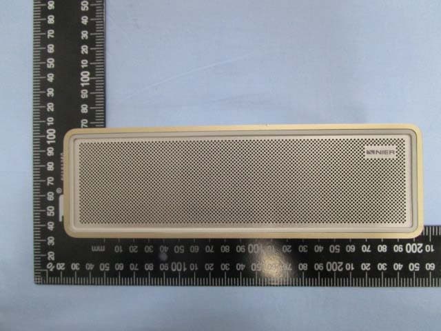
TQMIROCKMINI
Jan 25, 2015Bluetooth Speaker
Equipment Class
DSS - Part 15 Spread Spectrum Transmitter
TQMNIERIROCK
May 14, 2014Bluetooth Speaker
Equipment Class
DTS - Digital Transmission System
TQMMBOX
Jan 07, 2014BLUETOOTH SPEAKER
Equipment Class
DSS - Part 15 Spread Spectrum TransmitterTQMWIRPTT01
Jun 21, 20102.4G WIRELESS PTT
Equipment Class
DXX - Part 15 Low Power Communication Device Transmitter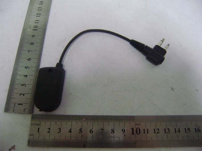
TQMDONGLE01
Jun 21, 20102.4G WIRELESS DONGLE
Equipment Class
DXX - Part 15 Low Power Communication Device Transmitter