TSEMCM-4Single Antenna Multi Channel Modem
Globalstar USA, LLC
Click to zoom
Application Details
- Equipment Class
- TNB - Licensed Non-Broadcast Station Transmitter
- Date of Grant
- Aug 15, 2006
- Application Purpose
- Original Equipment
- Date of Application
- Aug 15, 2006
- Equipment Note
- Single Antenna Multi Channel Modem
- Frequency Range
- 1610.00000000 - 1621.35000000
- Company
- Globalstar USA, LLC
- Country
- United States
Documents & Files
Document Text
Text extracted from the exhibit documents filed with the FCC. Open a document above to read the original.
Users Manual
Globalstar, Inc. 461 South Milpitas Blvd Milpitas, CA 95035 USA Globalstar MCM-4e Single Antenna Multi Channel Modem Installation & Operation Manual GS-06-1095 Publication Date: 1 May, 2006 Globalstar CAGE Code: 1WSX0 Copyright © Globalstar, Inc., 2006. All rights reserved Printed in the United States of America. Your System Information: MCM-4e Serial # : _______________________ Antenna Serial # : _______________________ VPN Tunnel Name: _______________________ IP Address: _______________________ Globalstar, Inc. 461 South Milpitas Blvd Milpitas, CA 95035 USA The MCM-4e System is manufactured in the United States by CornerTurn, LLC. TRADEMARKS : QUALCOMM® is a registered trademark of QUALCOMM Incorporated. Globalstar™ is a trademark of Globalstar, Inc. CornerTurn, LLC products are made in the USA SAFETY ISSUES: Your Multi Channel Modem System incorporates radio transmitters, receivers, and an antenna that receives and sends radio frequency (RF) energy. RADIO FREQUENCY ENERGY WARNING - The transmitted RF field intensity at the surface of the transmitting antenna is fairly high. Do not use when someone is within 29 inches (0.74 meters) of the antenna. COMPLIANCE WITH REGULATIONS Your Multi Channel Modem has been type approved by the FCC. Nonetheless, RF field intensity at the surface of the transmitting Globalstar antenna is fairly high. NCRP Report 86 (1986) National Council on Radiation Protection and Measurements FCC Radio Frequency Radiation Exposure Limits, 47 CFR Ch. 1 (10-1-98 Edition) Part 1,§1.1310 ANSI/IEEE C95.1-1992 Standard, American National Standards Institute IRPA (1991) Guidelines on Protection Against Non-Ionizing Radiation, International Radiation Protection Association ICNIRP (1996), International Commission on Non-Ionizing Radiation Protection Globalstar MCM-4e TABLE OF CONTENTS i 1. Operation ..................................................................................................................................1 1.1. Basic Satellite Information........................................................................................................................1 1.2. Key Points About Your Equipment .........................................................................................................1 1.3. System Start-Up From the Multi Channel Modem (MCM-4e) .............................................................2 1.4. Using Internet Data Services ....................................................................................................................3 1.5. Receiving Incoming Data Calls.................................................................................................................3 2. Provisioning the Single Antenna MCM-4e ............................................................................1 2.1. Service provisioning ..................................................................................................................................1 2.2. Roaming Outside of the ‘Home’ Service Area ........................................................................................1 3. Installation ................................................................................................................................2 3.1. Components of the System ........................................................................................................................2 3.2. Planning Where to Position the Components..........................................................................................3 3.2.1. Site Selection ....................................................................................................................................3 3.2.2. Single Piece Antenna ........................................................................................................................3 3.2.3. Multi Channel Modem (MCM-4e)....................................................................................................4 3.2.4. Remote Client Terminals and Other Networking Equipment ...........................................................4 3.3. Preparing for Installation .........................................................................................................................4 3.3.1. Inventory ...........................................................................................................................................4 3.3.2. Other Materials Needed ....................................................................................................................4 3.4. Antenna Installation ..................................................................................................................................4 3.5. Multi Channel Modem (MCM-4e) Installation.......................................................................................5 3.6. RJ-45 Ethernet Cable Routing .................................................................................................................6 3.7. Turn Power ON .........................................................................................................................................6 3.8. Install and Setup Remote Client Equipment...........................................................................................6 3.8.1. To configure remote client terminals with MS Windows XP operating system ...............................6 3.8.2. To configure remote client terminals with MS Windows 2000 operating system ............................9 3.8.3. To configure remote client terminals with MS Windows 98 operating system; .............................11 4. Cascaded MCM-4e Set-up ......................................................................................................1 4.1. Multi Channel Modem (MCM- 4e) Cascaded Set-up Front Panel........................................................1 4.2. Multi Channel Modem (MCM- 4e) Cascaded Set-up Rear Panel .........................…
Text truncated - open the document above for the full version.
External Photos
EXHIBIT C - EUT PHOTOGRAPHS Modem Front View Modem Rear View Modem Top View Power Supply
ID Label/Location Info
EXHIBIT A - FCC ID LABEL INFORMATION FCC ID Label Contents Proposed Label Location on EUT FCC ID: TSEMCM-4 Industry Canada Industrie Canada IC: 6197A-MCM-4
Internal Photos
Chassis Cover Off View Antenna Bottom View Antenna End View Antenna Side View Antenna Top View Data modem board 2 Component side View Data modem board 2 Solder side View Data modem Component side View Data modem Solder side View RF Shielding Off View 1 RF Shielding Off View 2 RF Shielding Off View 3 END OF REPORT
Parts List/Tune Up Info
Globalstar Proprietary 1 MCM-4e Tune-up procedure GS–06-1155 Version 1.0 8 June 2006 All data and information contained in or disclosed by this document are confidential and proprietary information of Globalstar, Inc. and its affiliates and all rights therein are expressly reserved. By accepting this material, the recipient agrees that the information contained herein will be held in confidence and in trust and will not be used, copied, or reproduced in whole or in part, nor its contents revealed in any manner to others without the express written permission of Globalstar, Inc. The U.S. Government regulates export of this technology or software. Diversion contrary to U.S. law is prohibited. Copyright © Globalstar, Inc., 2006. All rights reserved. Printed in the United States of America. Globalstar Proprietary 2 1.0 Purpose This document describes the procedure to tune-up the MCM-4e and the remote antenna equipment to ensure that the output power of the remote antenna is ensured to be below the level of the specified peak output power. 2.0 Tune-up Procedure Figure 1 shows the high level block diagram of the MCM-4e and Remote antenna configuration. Figure 2 shows the block and level diagram of the transmit section of the remote antenna. Figure 3 shows the detail schematics of the remote antenna. Following steps describe the procedure to tune-up the remote antenna equipment to ensure that the output power of the remote antenna does not exceed the peak specified output power of 32.5 dBm: 1. Inject 20.7 dBm CDMA signal at 1610.73 MHz generated by a signal generator at the Tx In port of the remote antenna. 2. Measure the output power at the Tx out port (at the output of ATT1 as shown in Figure 3). 3. If the output power measured by the power meter exceeds 32.5 dBm, then adjust ATT1 till the output power is less than 32.5 dBm. Figure 1 High Level Block diagram of MCM-4e configuration Tx In Tx Out Remote Antenna Globalstar Proprietary 3 Figure 2 Block and level diagram of the transmit section of the remote antenna Figure 3 Schematics of Remote antenna for MCM-4e A dobe Sy stems
Test Report
FCC PART 25 TYPE APPROVAL EMI MEASUREMENT AND TEST REPORT For Globalstar USA, LLC 461 S. Milpitas Blvd. Milpitas, CA 95035, U.S.A. FCC ID: TSEMCM-4 This Report Concerns: Original Report Product name: Single Antenna Multi Channel Modem Test Engineer: Snell Leong Report No.: R0604112 Report Date: 2006-05-10 Reviewed By: James Ma Prepared By: Bay Area Compliance Laboratory Corporation (BACL) 1274 Anvilwood Ave. Sunnyvale, CA 94089 Tel: (408) 732-9162 Fax: (408) 732 9164 TABLE OF CONTENTS GENERAL INFORMATION.......................................................................................................................................4 PRODUCT DESCRIPTION FOR EQUIPMENT UNDER TEST (EUT) ....................................................................................4 MECHANICAL DESCRIPTION.........................................................................................................................................4 EUT PHOTO.................................................................................................................................................................5 OBJECTIVE...................................................................................................................................................................5 RELATED SUBMITTAL(S)/GRANT(S).............................................................................................................................5 TEST METHODOLOGY..................................................................................................................................................5 TEST FACILITY.............................................................................................................................................................6 SYSTEM TEST CONFIGURATION..........................................................................................................................7 JUSTIFICATION.............................................................................................................................................................7 EUT EXERCISE SOFTWARE..........................................................................................................................................7 SPECIAL ACCESSORIES.................................................................................................................................................7 EQUIPMENT MODIFICATIONS.......................................................................................................................................7 LOCAL SUPPORT EQUIPMENT LIST AND DETAILS........................................................................................................7 POWER SUPPLY INFORMATION.....................................................................................................................................7 EXTERNAL I/O CABLING LIST AND DETAILS...............................................................................................................7 TEST SETUP BLOCK DIAGRAM.....................................................................................................................................8 SUMMARY OF TEST RESULTS ...............................................................................................................................9 §1.1307(B)(1) & §2.1091 - RF EXPOSURE...............................................................................................................10 §2.1047 – MODULATION CHARACTERISTICS ..................................................................................................11 §2.1051 – SPURIOUS EMISSIONS AT ANTENNA TERMINALS.......................................................................12 STANDARD APPLICABLE............................................................................................................................................12 MEASUREMENT PROCEDURE.....................................................................................................................................12 EQUIPMENT LISTS......................................................................................................................................................12 MEASUREMENT RESULT............................................................................................................................................12 §15.107 - CONDUCTED EMISSIONS ......................................................................................................................23 MEASUREMENT UNCERTAINTY..................................................................................................................................23 EUT SETUP................................................................................................................................................................23 TEST EQUIPMENT LIST AND DETAILS.........................................................................................................................23 TEST PROCEDURE......................................................................................................................................................23 TEST RESULTS SUMMARY..........................................................................................................................................23 CONDUCTED EMISSIONS TEST DATA.........................................................................................................................24 § 2.1053 & §25.202 (F) – FIELD STRENGTH OF SPURIOUS RADIATION ......................................................27 STANDARD APPLICABLE............................................................................................................................................27 MEASUREMENT PROCEDURE.....................................................................................................................................27 EQUIPMENT LISTS...............…
Text truncated - open the document above for the full version.
Contact Information
Applicant
Anthony J Navarra(President)
Test Firm
Bay Area Compliance LaboratoryJohn Chan
Technical Specifications
| # | Rule Parts | Frequency Range | Power Output | Emission | Tolerance |
|---|---|---|---|---|---|
| 1 | 25 | 1.61 GHz - 1.62 GHz | 3.54 W | 1M23G1W | 2.2000000000 ppm |
Other Applications from Globalstar USA, LLC

TSEMCM-4M
May 08, 2007Four Channel Satellite Modem
Equipment Class
TNB - Licensed Non-Broadcast Station Transmitter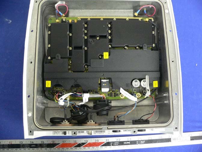
TSEFAU200RA
Jan 02, 2007Globalstar Fixed Access Unit with Remote Antenna
Equipment Class
TNB - Licensed Non-Broadcast Station Transmitter