TSEMCM-4MFour Channel Satellite Modem
Globalstar USA, LLC
Click to zoom
Application Details
- Equipment Class
- TNB - Licensed Non-Broadcast Station Transmitter
- Date of Grant
- May 08, 2007
- Application Purpose
- Original Equipment
- Date of Application
- Feb 28, 2007
- Equipment Note
- Four Channel Satellite Modem
- Frequency Range
- 1610.00000000 - 1621.35000000
- Company
- Globalstar USA, LLC
- Country
- United States
Documents & Files
Document Text
Text extracted from the exhibit documents filed with the FCC. Open a document above to read the original.
Users Manual
Globalstar, Inc. 461 South Milpitas Blvd Milpitas, CA 95035 USA Globalstar MCM-4M Single Antenna Multi Channel Modem Installation & Operation Manual GS-06-1095 (Preliminary) Publication Date: 17 January, 2007 Globalstar CAGE Code: 1WSX0 Copyright © Globalstar, Inc., 2007. All rights reserved Printed in the United States of America. Your System Information: MCM-4M Serial # : _______________________ Antenna Serial # : _______________________ VPN Tunnel Name: _______________________ IP Address: _______________________ Globalstar, Inc. 461 South Milpitas Blvd Milpitas, CA 95035 USA The MCM-4M System is manufactured in the United States by CornerTurn, LLC. TRADEMARKS: QUALCOMM® is a registered trademark of QUALCOMM Incorporated. Globalstar™ is a trademark of Globalstar, Inc. CornerTurn, LLC products are made in the USA SAFETY ISSUES: Your Multi Channel Modem System incorporates radio transmitters, receivers, and an antenna that receives and sends radio frequency (RF) energy. RADIO FREQUENCY ENERGY WARNING - The transmitted RF field intensity at the surface of the transmitting antenna is fairly high. Do not use when someone is within 29 inches (0.74 meters) of the antenna. COMPLIANCE WITH REGULATIONS Your Multi Channel Modem has been type approved by the FCC. Nonetheless, RF field intensity at the surface of the transmitting Globalstar antenna is fairly high. NCRP Report 86 (1986) National Council on Radiation Protection and Measurements FCC Radio Frequency Radiation Exposure Limits, 47 CFR Ch. 1 (10-1-98 Edition) Part 1,§1.1310 ANSI/IEEE C95.1-1992 Standard, American National Standards Institute IRPA (1991) Guidelines on Protection Against Non-Ionizing Radiation, International Radiation Protection Association ICNIRP (1996), International Commission on Non-Ionizing Radiation Protection Globalstar MCM- 4M TABLE OF CONTENTS i 1. Operation.........................................................................................................................1-1 1.1. Basic Satellite Information...............................................................................................................1-1 1.2. Key Points About Your Equipment................................................................................................. 1-1 1.3. System Start-Up From the Multi Channel Modem (MCM-4M) .....................................................1-2 1.4. Using Internet Data Services............................................................................................................1-2 1.5. Receiving Incoming Data Calls........................................................................................................1-3 2. Provisioning the Single Antenna MCM-4M...................................................................2-1 2.1. Service provisioning.........................................................................................................................2-1 2.2. Roaming Outside of the ‘Home’ Service Area.................................................................................2-1 3. Installation.......................................................................................................................3-2 3.1. Components of the System...............................................................................................................3-2 3.2. Planning Where to Position the Components..................................................................................3-3 3.2.1. Site Selection...........................................................................................................................3-3 3.2.2. Single Piece Antenna...............................................................................................................3-3 3.2.3. Multi Channel Modem (MCM-4M) ..........................................................................................3-4 3.2.4. Remote Client Terminals and Other Networking Equipment.....................................................3-4 3.3. Preparing for Installation................................................................................................................3-4 3.3.1. Inventory ................................................................................................................................. 3-4 3.3.2. Other Materials Needed............................................................................................................3-4 3.4. Antenna Installation.........................................................................................................................3-4 3.5. Multi Channel Modem (MCM-4M) Installation..............................................................................3-5 3.6. RJ-45 Ethernet Cable Routing.........................................................................................................3-6 3.7. Turn Power ON................................................................................................................................3-6 3.8. Install and Setup Remote Client Equipment...................................................................................3-6 3.8.1. To configure remote client terminals with MS Windows XP operating system...........................3-6 3.8.2. To configure remote client terminals with MS Windows 2000 operating system........................3-9 3.8.3. To configure remote client terminals with MS Windows 98 operating system;........................3-11 4. Cascaded MCM-4M Set-up............................................................................................4-1 4.1. Multi Channel Modem (MCM- 4e) Cascaded Set-up Front Panel..................................................4-1 5. Troubleshooting...............................................................................................................5-1 5.1. General Troubleshooting.....................................................................................................…
Text truncated - open the document above for the full version.
Attestation Statements
Bay Area Compliance Laboratories Corp., 1274 Anvilwood Ave. Sunnyvale, CA 94089, USA www.baclcorp.com Globalstar Audit Responses: FCC ID: TSEMCM-4M Federal Communications Commission Authorization and Evaluation Division To Whom It May Concern: Copied below is the original correspondence sent by the FCC concerning Globalstar FCC ID: TSEMCM-4M, please see their responses in blue bold-faced type. Also please see revised test report that includes updated excerpts and responses to the applicable standard. Should there be any further question in this matter please feel free to contact us at [email protected] Douglas Mendez BACL Document Control Supervisor Phone: (408) 732-9162 x3038 Fax: (408) 732-9164 To: Anthony Navarra From: Tim Harrington ([email protected] ) FCC Equipment Authorization Branch Re: FCC ID: TSEMCM-4M Applicant: Globalstar USA, LLC Correspondence Reference Number: 38596 731 Confirmation Number: ******** Date of Original Email: 05/10/2007 Subject: audit ------------------------------------------------------------------------ NOTE - This Certification grant was previously subject to administrative action based on 25.129 being applicable only for portable devices as defined by 2.1093, deletion of 25.200 optional Certification by 67 FR 61816 for other GMPCS devices such as 2.1091-mobile, and the situation that 99-67 docket record at FCC EDOCS search page did not address DA-02-1578 (DOC- 224026). Although FCC has re-issued this Certification grant based on above general considerations, certain additional info is needed to address 47 CFR sec. 2.962, 2 subpart J (2-J), part 25, including the following. TCB please coordinate response to following: Bay Area Compliance Laboratories Corp., 1274 Anvilwood Ave. Sunnyvale, CA 94089, USA www.baclcorp.com 1) This device appears to consist of a rack-mounted enclosure "modem" with a separate antenna unit, therefore it appears to be what is considered a fixed-mounted device with respect to FCC RF exposure rules. Please explain whether and how this device qualifies as a "mobile earth station," i.e. per 25.201, such that 25.216 etc are applicable as reported herein. Response: "This is a portable desktop device with the option of installing rack-mount brackets. The device is designed primarily for portable and mobile applications but may also be used for ancillary fixed applications as permitted in Globalstar’s mobile earth station license (see Airtouch Satellite Services US, Inc. [now GUSA Licensee LLC], Order and Authorization, DA 99-2010 (Oct. 4, 1999), at para. 22)." 2) Based on DA-02-1578 and discussions in FCC-03-283, FCC OET Lab will allow optional 2-J Certifications for some part 25 devices, namely such devices covered under the conventional station-class definition of mobile, which generally encompasses devices covered by 2.1093- portable and 2.1091-mobile. Per 03-283, neither required nor optional Certification is appropriate for general feeder-link transmitters, which this device seems to be. Please explain whether and how this device qualifies as an "end user terminal," "positioned at one end of a communication channel," per intent of docket 99-67, or submit letter from applicant requesting application dismissal. Response: As described the response to 1) above, the MCM-4M is a multi channel earth station device used by a subscriber to transmit and receive data via satellite. 3) User manual indicates aircraft-mount for antenna is intended - per FCC-03-283, 2-J Certification is not applicable for transceivers "designed for installation in aircraft or maritime vessels." Please explain, or submit letter from applicant requesting application dismissal. Response: The aircraft and maritime references have been removed in the updated version of the MCM-4M user manual. 4) Pending resolution of above items, adjustments may be needed in this filing for RF exposure compliance information and grant remarks. Response: Globalstar intends to proceed with the filing. A 30 cm minimum separation mounting point requirement is specified in the revised user manual. This is a practical mounting requirement and meets the FCC RF exposure rules specified in the Office of Engineering and Technology (OET) Bulletin 65. Bay Area Compliance Laboratories Corp., 1274 Anvilwood Ave. Sunnyvale, CA 94089, USA www.baclcorp.com 5) Pending resolution of preceding items, please include the following in grant remarks: In accordance with DA-02-1578 and FCC-03-283, this is an optional Certification for an earth- station transceiver designed for operation by end users of satellite communication services. Response: The grant remarks will be added as instructed ------------------------------------------------------------------------ The items indicated above must be submitted before processing can continue on the above referenced application. Failure to provide the requested information within 30 days of the original e-mail date may result in application dismissal pursuant to Section 2.917(c).
Cover Letter(s)
Globalstar, Inc. Tel: (408) 933-4000 461 South Milpitas Blvd. Fax: (408) 933-4100 Milpitas, CA 95035 www.globalstar.com 2007-01-15 Federal Communications Commission (FCC) Authorization and Evaluation Division 445 12th Street, SW Washington, DC 20554 Subject: Confidentiality Request regarding application for certification of FCC ID: TSEMCM-4M Pursuant to Sections 0.457 and 0.459 of the Commission’s Rules, Globalstar, Inc. hereby requests permanent confidential treatment of information accompanying this application as outlined below: • Block Diagrams • Schematics • Parts List The above materials contain trade secrets and proprietary information not customarily released to the public. The public disclosure of these materials may be harmful to the applicant and provide unjustified benefits to its competitors. The applicant understands that pursuant to Section 0.457 of the Rules, disclosure of this application and all accompanying documentation will not be made before the date of the Grant fro this application. Very Truly Yours, Globalstar, Inc. ______________________ Kirk C. Henesian Contracts Manager
External Photos
Globalstar USA, LLC FCC ID: TSEMCM-4M Report # R0612141-25 Page 51 of 61 FCC Part 25 Test Report EXHIBIT C - EUT PHOTOGRAPHS EUT - Front View EUT - Rear View
External Photos
Globalstar USA, LLC FCC ID: TSEMCM-4M Report # R0612141-25 Page 58 of 61 FCC Part 25 Test Report 2.3 dBi Antenna – Top View 2.3 dBi Antenna – Side View Globalstar USA, LLC FCC ID: TSEMCM-4M Report # R0612141-25 Page 59 of 61 FCC Part 25 Test Report 2.3 dBi Antenna – Bottom View 4.5 dBi Antenna – Top View Globalstar USA, LLC FCC ID: TSEMCM-4M Report # R0612141-25 Page 60 of 61 FCC Part 25 Test Report 4.5 dBi Antenna – Side View 4.5 dBi Antenna – Bottom View Globalstar USA, LLC FCC ID: TSEMCM-4M Report # R0612141-25 Page 61 of 61 FCC Part 25 Test Report Power Supply – Top View Power Supply – Bottom View END OF REPORT
ID Label/Location Info
Globalstar USA, LLC FCC ID: TSEMCM-4M Report # R0612141-25 Page 46 of 61 FCC Part 25 Test Report EXHIBIT A - FCC ID LABEL INFORMATION FCC § 2.925 Identification of equipment (a) Each equipment covered in an application for equipment authorization shall bear a nameplate or label listing the following: (1) FCC Identifier consisting of the two elements in the exact order specified in §2.926. The FCC Identifier shall be preceded by the term FCC ID in capital letters on a single line, and shall be of a type size large enough to be legible without the aid of magnification. Example: FCC ID XXX123. XXX—Grantee Code 123—Equipment Product Code Suggested Content of FCC ID Label Proposed Label Location on EUT The label shall not be a stick-on, paper label. The label on these products shall be permanently affixed to the product and shall be readily visible to the purchaser at the time of purchase, as described in Section 2.925(d) of this chapter. "Permanently affixed" means that the label is etched, engraved, stamped, silk- screened, indelibly printed, or otherwise permanently marked on a permanently attached part of the equipment or on a nameplate of metal, plastic, or other material fastened to the equipment by welding, riveting, or a permanent adhesive. The label must be designed to last the expected lifetime of the equipment in the environment in which the equipment may be operated and must not be readily detachable. FCC ID: TSEMCM-4M Industry Canada Industrie Canada IC: 6197A-MCM-4M
Internal Photos
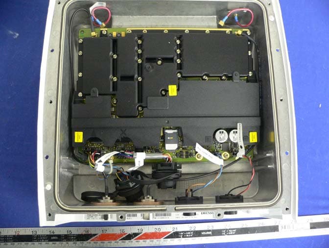
Globalstar USA, LLC FCC ID: TSEMCM-4M Report # R0612141-25 Page 52 of 61 FCC Part 25 Test Report EUT Cover off - Top View Modem Board with attached RF Board and shielding - Top View Globalstar USA, LLC FCC ID: TSEMCM-4M Report # R0612141-25 Page 53 of 61 FCC Part 25 Test Report Modem Board with attached Board - Bottom View Modem Board without shielding - Top View Globalstar USA, LLC FCC ID: TSEMCM-4M Report # R0612141-25 Page 54 of 61 FCC Part 25 Test Report Attached Modem Board with shielding - Top View Attached Modem Board without shielding - Top View Globalstar USA, LLC FCC ID: TSEMCM-4M Report # R0612141-25 Page 55 of 61 FCC Part 25 Test Report Attached Modem Board without shielding - Rear View Power Divider - Combiner Globalstar USA, LLC FCC ID: TSEMCM-4M Report # R0612141-25 Page 56 of 61 FCC Part 25 Test Report Radio Card 1 – Top View Radio Card 1 – Bottom View Globalstar USA, LLC FCC ID: TSEMCM-4M Report # R0612141-25 Page 57 of 61 FCC Part 25 Test Report Radio Card 2 – Top View Radio Card 2 – Bottom View
Operational Description
Globalstar MCM- 4M OPERATION 1-1 1. Operation Your Multi Channel Modem System is easy to use, versatile, and dependable. When configured properly, all 4 channels can be combined to provide an aggregate Internet connection equivalent to a 28 Kbps modem. If two, three or 4 units are available and configured for cascaded operations you can achieve an aggregate Internet connection equivalent to a 112 Kbps modem. Internet access is available in all Globalstar™ network data services coverage areas except those for China and Nicaragua. WARNING - The transmitted RF field intensity at the surface of the transmitting antenna is fairly high. Do not use when someone is within 29 inches (0.74 meters) of the antenna. 1.1. Basic Satellite Information Globalstar satellites operate in an inclined orbit of 52 degrees. They come up over a point on the western horizon, move across the sky, and then drop behind the eastern horizon. The average user cannot predict the path of the satellites. Each satellite will pass from horizon to horizon in about 10-15 minutes. When the MCM-4M is located in moderate latitudes (22-52 degrees) it will communicate with at least TWO satellites passing over your geographic location. This system uses high frequency microwave signals. Unlike television and AM or FM radio signals, or even cellular phone signals, microwave radio signals do not bend and are strictly line of sight. This means that these signals do not go through, or around, dense objects including the platform’s own superstructure, wings or masts. It can not go through, or around, other objects adjacent to the platform either (trees, buildings, overhangs, cranes, tall hills or mountains). If something gets between the satellite and the antenna the data connection won’t work until another satellite (which is not blocked) is received or the platform moves to a location where your antenna will no longer be blocked by the object. If the antenna is no longer pointed up toward the overhead location of the satellites, the data connection won’t work until the antenna has a clear view of the sky above again. If the MCM-4M antenna’s view of the sky above 10 o elevation is restricted, the unit will suffer temporary data rate reductions. If the antenna is completely blocked, the signal to/from the satellite will be lost until the signal path is unobstructed. 1.2. Key Points About Your Equipment The MCM-4M provides you with data access over the Globalstar satellite network. In some geographic areas setup, configuration and usage may be slightly different. Subject to certain constraints, the MCM-4M is capable of dial up packet or asynchronous operation in any Globalstar service area. These constraints, and the service limitations, are described in Section 2. The MCM-4M provides the ability to establish up to four concurrent satellite connections each providing 7.2 Kbps of raw symmetrical bandwidth. The MCM-4M provides the combined bandwidth to the user via a single standard Ethernet connection. The MCM-4M is a full duplex device and can be configured to allow other data terminals to initiate a data communications connection. For this purpose, any of the four SDMs may be configured to receive an incoming asynchronous data call from a PSTN modem. The MCM-4M unit can be connected to up to 3 additional MCM-4M units to provide the combined bandwidth of up to sixteen concurrent satellite connections. The MCM-4M requires connection to an Antenna Assembly to be mounted on an external surface. The MCM-4M contains an Multi-Channel Processor board and four QUALCOMM GSP-1620 Satellite Data Modems (SDM). The MCM-4M also includes an Ethernet 10 Base-T port, power supplies, converters, and management functions. Globalstar MCM- 4M OPERATION 1-2 The 10/100 BaseT Ethernet port can be connected to multiple remote client terminals through a suitable hub or switch. It provides the path through the Globalstar network for your remote client terminal(s) to communicate. Your connection may be to a public server site or you may be connected to a private site such as a Virtual Private Network (VPN). In normal operation the MCM-4M provides you with a PATH to and from the Internet, which allows your mobile platform to be connected without having wires attached to it. You operate the remote client terminal exactly the same way you would if it were connected to any other Ethernet LAN. When the MCM-4M is operating normally, it provides the path to and from the Internet and will be transparent to you. Refer to figure 2-1 for an overview of the satellite connection. Figure 1-1 MCM-4M being used to connect to the Internet 1.3. System Start-Up From the Multi Channel Modem (MCM-4M) Figure 1-2 MCM-4M Multi Channel Modem – Front Panel 1.4. Using Internet Data Services To set up the PC computer for data service use, refer to section 4. 1. To use the Internet Data services for Internet browsing, email and file transfers, open your Internet browser, email or other data program and proceed by operating that program as you normally would to browse, email or efax. Please refer to the accompanying Software and User Documentation for instructions on how to operate the MCM-4M and to turn the tunnel on.
Parts List/Tune Up Info
MCM-4 TUNE-UP PROCEDURE (This page intentionally left blank for Globalstar to fill-in) 1.0 PURPOSE This document describes the tune-up procedure to set the MCM-4 and Remote Active Antenna (RAA) to the appropriate level to ensure that the peak RF output power is not exceeded. 2.0 TUNE-UP PROCEDURE Fig. 1 shows an overall view of the test set up used to perform the RF output power adjustment to the RAA unit. Since the modems are only capable of putting out a max RF power of +26dBm, the use of only two Modems produces an output power of about +22.3dBm at the “Transmit” port of the MCM-4 unit. With the use of a 53ft LMR-300 Cable, the incurred losses would be approximately 4.5dB so by the time the CDMA signal reaches the Tx input port of the RAA, the RF level will be in the order of 17.8dBm composite power. To emulate four modems we need to lower the loss between the MCM-4 and the RAA unit by 3dB. So to ensure an input power level to the RAA of 20.8dBm, 1.5dB of losses must be implemented between the Transmit port of the MCM-4 and the TX input port of the RAA. The steps to make the power adjustments are summarized as follow: 1. Inject a 20.8dBm composite power level to the TX input port of the RAA unit. Use channels 8 and 9. 2. Measure the composite output power level at the TX output connector of the RAA. For this step to occur, it will be necessary to detach the antenna assembly from the rest of the RAA unit. 3. Open the RAA unit and proceed to adjust the output power of the unit by adjusting the POT. The location of the POT in the PCB board is as indicated in Fig. 2. Set the power level to +31dBm.
RF Exposure Info
Globalstar USA, LLC FCC ID: TSEMCM-4M Report # R0612141-25 Page 10 of 61 FCC Part 25 Test Report §1.1307(b) (1) & §2.1091 - RF EXPOSURE According to §1.1307(b)(1), systems operating under the provisions of this section shall be operated in a manner that ensures that the public is not exposed to radio frequency energy level in excess of the Commission’s guidelines. According to §1.1310 and §2.1091 RF exposure is calculated. Limits for General Population/Uncontrolled Exposure Frequency Range (MHz) Electric Field Strength (V/m) Magnetic Field Strength (A/m) Power Density (mW/cm 2 ) Averaging Time (minute) Limits for General Population/Uncontrolled Exposure 0.3-1.34 614 1.63 *(100) 30 1.34-30 824/f 2.19/f *(180/f 2 ) 30 30-300 27.5 0.073 0.2 30 300-1500 / / f/1500 30 1500-100,000 / / 1.0 30 f = frequency in MHz * = Plane-wave equivalent power density MPE Prediction Prediction of MPE limit at a given distance Equation from page 18 of OET Bulletin 65, Edition 97-01 S = PG/4πR² Where: S = power density P = power input to antenna G = power gain of the antenna in the direction of interest relative to an isotropic radiator R = distance to the center of radiation of the antenna Globalstar USA, LLC FCC ID: TSEMCM-4M Report # R0612141-25 Page 11 of 61 FCC Part 25 Test Report 2.3 dBi antenna 4.5 dBi antenna Test Result The power density of predication frequency at 73.7 cm is 0.072 mW/cm 2 for the 4.5 dBi antenna and 0.045 mW/cm 2 for the 2.3 dBi antenna, both of which were according to calculation under the MPE limit for uncontrolled exposure of 1.00 mW/cm 2 . Maximum peak output power at antenna input terminal (dBm): 32.53(dBm ) Maximum peak output power at antenna input terminal (mW): 1790.61 (mW) Predication distance (cm): 73.70 cm Predication frequency (MHz): 1615.65 (MHz) Maximum Antenna Gain, typical (dBi): 2.3 (dBi) Maximum Antenna Gain (numeric): 1.698 (numeric) Power density of predication frequency at 73.7 cm (mW/cm 2 ): 0.045 (mW/cm 2 ) MPE limit for uncontrolled exposure at predication frequency (mW/cm 2 ): 1.00 (mW/cm 2 ) Maximum peak output power at antenna input terminal (dBm): 32.53(dBm ) Maximum peak output power at antenna input terminal (mW): 1790.61 (mW) Predication distance (cm): 73.70 cm Predication frequency (MHz): 1615.65 (MHz) Maximum Antenna Gain, typical (dBi): 4.5 (dBi) Maximum Antenna Gain (numeric): 2.818 (numeric) Power density of predication frequency at 73.7 cm (mW/cm 2 ): 0.072 (mW/cm 2 ) MPE limit for uncontrolled exposure at predication frequency (mW/cm 2 ): 1.00 (mW/cm 2 )
Test Report
Note: This test report is for the customer shown above and their specific product only. It may not be duplicated or used in part without prior written consent from Bay Area Compliance Laboratories Corp. This report must not be used by the customer to claim product certification, approval, or endorsement by NVLAP, NIST, or any agency of the Federal Government (REV.1) FCC PART 25 TYPE APPROVAL MEASUREMENT AND TEST REPORT For Globalstar USA, LLC 461 S. Milpitas Blvd. Milpitas, CA 95035, U.S.A. FCC ID: TSEMCM-4M This Report Concerns: Original Report Product name: Modular Four-Channel Satellite Modem Test Engineer: James Ma Report Number: R0612141-25 Report Date: 2007-02-07 Reviewed By: Hans Mellberg, VP of Engineering Prepared By (J8): Bay Area Compliance Laboratory Corporation (BACL) 1274 Anvilwood Ave. Sunnyvale, CA 94089 Tel: (408) 732-9162 Fax: (408) 732 9164 Globalstar USA, LLC FCC ID: TSEMCM-4M Report # R0612141-25 Page 2 of 61 FCC Part 25 Test Report TABLE OF CONTENTS GENERAL INFORMATION.......................................................................................................................................4 PRODUCT DESCRIPTION FOR EQUIPMENT UNDER TEST (EUT) .....................................................................................4 EUT PHOTO.................................................................................................................................................................4 MECHANICAL DESCRIPTION.........................................................................................................................................4 OBJECTIVE...................................................................................................................................................................5 RELATED SUBMITTAL(S)/GRANT(S).............................................................................................................................5 TEST METHODOLOGY..................................................................................................................................................5 MEASUREMENT UNCERTAINTY....................................................................................................................................5 TEST FACILITY.............................................................................................................................................................5 SYSTEM TEST CONFIGURATION ..........................................................................................................................7 JUSTIFICATION.............................................................................................................................................................7 EUT EXERCISE SOFTWARE..........................................................................................................................................7 SPECIAL ACCESSORIES.................................................................................................................................................7 EQUIPMENT MODIFICATIONS.......................................................................................................................................7 LOCAL SUPPORT EQUIPMENT LIST AND DETAILS........................................................................................................7 POWER SUPPLY INFORMATION.....................................................................................................................................7 EXTERNAL I/O CABLING LIST AND DETAILS................................................................................................................7 TEST SETUP BLOCK DIAGRAM.....................................................................................................................................8 SUMMARY OF TEST RESULTS ...............................................................................................................................9 §1.1307(B) (1) & §2.1091 - RF EXPOSURE..............................................................................................................10 §2.1047 – MODULATION CHARACTERISTICS ..................................................................................................12 §2.1051 & §25 – SPURIOUS EMISSIONS AT ANTENNA TERMINALS............................................................13 STANDARD APPLICABLE............................................................................................................................................13 MEASUREMENT PROCEDURE......................................................................................................................................13 EQUIPMENT LISTS......................................................................................................................................................13 MEASUREMENT RESULT............................................................................................................................................13 §15.107 - CONDUCTED EMISSIONS .....................................................................................................…
Text truncated - open the document above for the full version.
Contact Information
Applicant
Anthony J Navarra(President)
Test Firm
Bay Area Compliance LaboratoryJohn Chan
Technical Specifications
| # | Rule Parts | Frequency Range | Power Output | Emission | Tolerance |
|---|---|---|---|---|---|
| 1 | 25 | 1.61 GHz - 1.62 GHz | 1.79 W | 1M25G9W | 0.0000800000 % |
Other Applications from Globalstar USA, LLC
TSEFAU200RA
Jan 02, 2007Globalstar Fixed Access Unit with Remote Antenna
Equipment Class
TNB - Licensed Non-Broadcast Station Transmitter
TSEMCM-4
Aug 15, 2006Single Antenna Multi Channel Modem
Equipment Class
TNB - Licensed Non-Broadcast Station Transmitter