TSK-RPC3G914RPSRadio Packet Controller Module.
Radiometrix Limited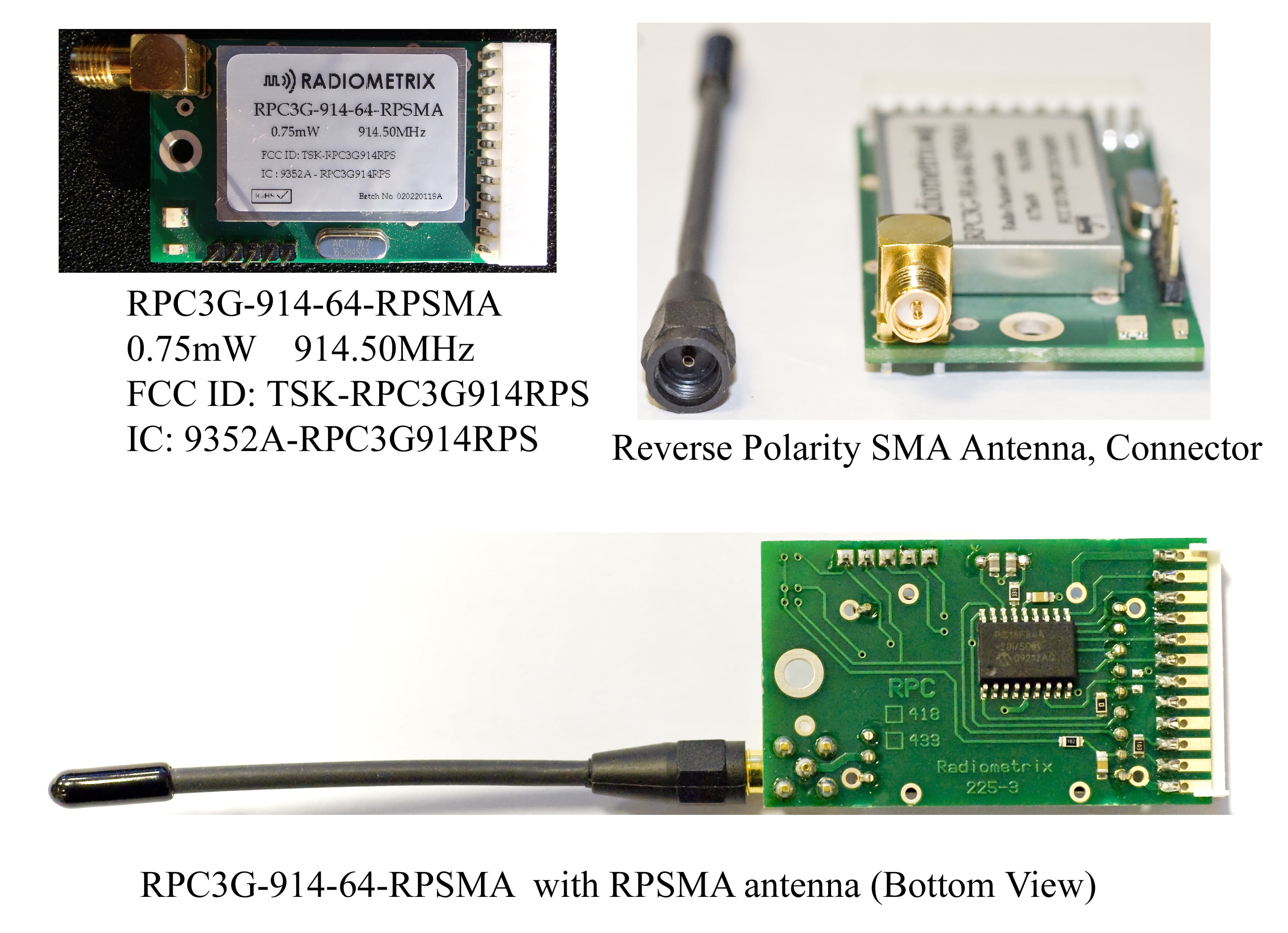
Click to zoom
Application Details
- Equipment Class
- DXT - Part 15 Low Power Transceiver, Rx Verified
- Date of Grant
- Aug 02, 2011
- Application Purpose
- Original Equipment
- Date of Application
- Aug 02, 2011
- Equipment Note
- Radio Packet Controller Module.
- Frequency Range
- 914.50000000 - 914.50000000
- Company
- Radiometrix Limited
- Country
- United Kingdom
Documents & Files
Document Text
Text extracted from the exhibit documents filed with the FCC. Open a document above to read the original.
Users Manual
Radiometrix Ltd, RPC3G page 1 ` FEATURES Crystal controlled PLL FM circuitry for both Tx and Rx Up to 50 meter in-building range, 200m open ground Built-in self-test / diagnostics / status LED’s Complies with ETSI EN 300 220-3 Complies with ETSI EN 301 489-3 Single 5V supply @ < 27mA 64kbps half duplex Free format packets of 1 - 27 bytes Packet framing and error checking are user transparent Collision avoidance (listen before transmit) Direct interface to 5V CMOS logic Power save mode INTRODUCTION The RPC3G is a self-contained plug-on radio port which requires only a simple antenna, 5V supply and a byte-wide I/O port on a host microcontroller (or bi-directional PC port). The module provides all the RF circuits and processor intensive low level packet formatting and packet recovery functions required to inter-connect an number of microcontrollers in a radio network. A data packet of 1 to 27 bytes downloaded by a Host microcontroller into the RPC3G's packet buffer is transmitted by the RPC3G’s transceiver and will "appear" in the receive buffer of all the RPC3G's within radio range. A data packet received by the RPC3G’s transceiver is decoded, stored in a packet buffer and the Host microcontroller signalled that a valid packet is waiting to be uploaded. RF specifications are provided on BiM3G-869-64, BiM3G-914-64 RF transceiver datasheet. Modules: RPC3G-914-64: IC + BiM3G-914-64 RPC3G-869-64: IC + BiM3G-869-64 IC’s: RPC-000-DIL: 18 pin DIL IC RPC-000-SO: 18 pin SO IC RPC-000-SS: 20 pin SSOP IC The RPC3G is an intelligent transceive r modules, which enable a radio network/link to be simply implemented between a number of digital devices. The module combines a BiM3G UHF RF transceiver an d a 64kbps packet controller. RPC3G-914-64-RPSMA module figure 1: RPC3G + Host -controller HOST HOST RPC3G download download upload upload transmit / receive 869/914 MHz Radio Packet Controller Issue 4, 1 August 2011 Hartcran House, 231 Kenton Lane, Harrow, Middlesex, HA3 8RP, England Tel: +44 (0) 20 8909 9595, Fax: +44 (0) 20 8909 2233, www.radiometrix.com RPC3G Radiometrix Ltd, RPC3G page 2 9.7mm 7.3mm 32mm 54mm 2.54mm 3.5mmmountinghole 0.1inch pitch connector pads suitable for pin headers,pin sockets, edge connectorsand ribbon cables antenna pads forterminal blockor SMB connector f i g ure 3: p h y sical dimensions 16.384 BiM3G-914-64 top view 12 GND11 Vc c10 RESET 9 RXA8 RXR7 TXA6 TXR5 D34 D23 D12 D01 GND TX RX RXD GND Audio RX LED TX LED RF GND figure 4: RPC3G’s pinout 16.384 BiM3G-914-64 Radiometrix Ltd, RPC3G page 3 1. FUNCTIONAL DESCRIPTION On receipt of a packet downloaded by the Host, the RPC3G will append to the packet: Preamble, start byte and a error check code. The packet is then coded for security and mark:space balance and transmitted through the BiM3G RF Transceiver as a 64kbps synchronous stream. One of four methods of collision avoidance (listen before TX) may be user selected. When not in transmit mode, the RPC3G continuously searches the radio noise for valid preamble. On detection of preamble, the RPC3G synchronises to the in-coming data stream, decodes the data and validates the check sum. The Host is then signalled that a valid packet is waiting to be unloaded. The format of the packet is entirely of the users determination except the 1st byte (the Control Byte) which must specify the packet type (control or data) and the packet size. A valid received packet is presented back to the host in exactly the same form as it was given. To preserve versatility, the RPC3G does not generate routing information (i.e. source/ destination addresses) nor does it handshake packets. These network specific functions should be performed by the host. Additional features of the RPC3G include extensive diagnostic/debug functions for evaluation and debugging of the radio and host driver software, a built in self test function and a sleep mode / wake-up mechanism which may be programmed to reduce the average current to less than 100A. The operating parameters are fully programmable by the host and held in EEPROM, the host may also use the EEPROM as a general purpose non-volatile store for addresses , routing information etc. 1.1 O PERATING STATES The RPC3G has four normal operating states: I DLE / SLEEP HOST TRANSFER TRANSMIT RECEIVE I DLE/SLEEP The I DLE state is the quiescent/rest state of the RPC3G. In IDLE the RPC3G enables the receiver and continuously searches the radio noise for message preamble. If the power saving modes have been enabled the RPC3G will pulse the receiver on, check for preamble and go back to S LEEP if nothing is found. The 'ON' time is 5ms, OFF time is programmable in the RPC3G’s EEPROM and can vary between 22ms and 2.9s. The TX Request line from the Host is constantly monitored and will be acted upon if found active (low). A TX Request will immediately wake the RPC3G up from S LEEP mode. H OST TRANSFERS If the host sets the TX Request line low a data transfer from the Host to the RPC3G will be initiated. Similarly the RPC3G will pull RX Request low when it requires to transfer data to the Host (this may polled or used to generate a Host interrupt). The transfer protocol is fully asynchronous, i.e. the host may service another interrupt and then continue with the RPC3G transfer. It is desirable that all transfers are completed quickly since the radio transceiver is disabled until the Host <> RPC3G transfer is completed. Typically a fast host can transfer a 27 byte packet to / from the RPC3G in under 1ms. T RANSMIT On receipt of a data packet from the host, the RPC3G will append to the packet - preamble, frame sync byte and an error check sum. The packet is then coded for mark:space balance and transmitted. A full 27 byte packet is transmitted in 8.1ms of TX air time (64kb/s + 5ms preamble). Collision avoidance (Listen Before Transmit-LBT) functions can be enabled to prevent loss of packets. Data packets may be sent with either normal or extended…
Text truncated - open the document above for the full version.
Block Diagram
RXD D0 D1 D2 D3 HOST INTERF ACE CONTROLLER PREAMBLE DETECT OR DATA CLOCK RECOVER Y PARALLEL CONVER TER SERIAL RX FRAME SYNC. DETECT PREAMBLE GENERA TOR CRC GENERA TOR/ CHECKER 27 BYTES TX/RX P ACKET BUFFER BYTE CODING 12 8 8 TXD TX RX CLOCK OSCILLA TOR data clk TX COLLISION AVOIDANCE POWER SAVE WATCH DOG DIAGNOSTICS SELF TEST STATE CONTROLLER CONTROL SWITCHES Address = 00 (RAM) H PARAMETER / DA TA STORE 63 BYTES E PROM 2 Address 01 -3F HH GND OSC2 Vdd OSC1 8 8 8 RX RX TX clk Fosc/256 TX data TXRTXARXA RXR RESET 330R 16.384MHz 22p 22p 10K 1 2 3 4 5 6 7 8 9 10 11 12 220nF 10nF 1K RX TX Radio Packet Controller RPC3G block diagram SIG BiM3G UHF Module RF data slicer Tx/Rx logic Vcc RXD (12) AF (13)GND (10) TXD (14) Vcc (17) 4.5V - 5.5V RSSI (11) TXselect (15) RX select(16) Mixer IF Amp Demod 10.7MHz buffer f ̧ 64 LoopFilter LPF 14.45625MHz LPF 64 ̧ LoopFilter ref osc f VCO VCO matching &lpf Tx/Rx switch 1k 869/914MHz bpf preamp 35KHz ref. osc 14.289843MHz
Cover Letter(s)
Agency Letter 26 April 2011 Telecommunication Certification Body RFI Global Services Ltd Pavilion A Ashwood Park Ashwood Way Basingstoke Hampshire RG23 8BG England To whom it may concern, Subject: Certification Application FCC ID: TSK-RPC3G914RPS This is to certify that Radiometrix Ltd authorises RFI Global Services Ltd to act on our behalf for the application of the RPC3G-914-64-RPSMA to RFI Global Services Ltd. Telecommunication Certification Body. We certify that we are not subject to a denial of Federal benefits, that include FCC benefits, pursuant to Section 5301 of the Anti-Drug Abuse Act of 1988, 21 U.S.C. § 862 because of a conviction for possession or distribution of a controlled substance. See 47 CFR 1.2002(b) for the definition of a "party" for these purposes. Yours sincerely Sabananthan Parmananthan Technical Manager
Cover Letter(s)
04 February 2011 Telecommunication Certification Body RFI Global Services Ltd. Pavilion A Ashwood Park Basingstoke Hampshire RG23 8BG United Kingdom Subject: Confidentiality Request; Certification Application FCC ID: TSK-RPC3G914RPS Pursuant to Sections 0.457 and 0.459 of CFR 47 Company Radiometrix Ltd request that the following information, provided to support the FCC application for the Equipment RPC3G-914-64-RPSMA, FCC ID: TSK-RPC3G914RPS, be held permanently confidential: Exhibit Name File reference name No. of pages BiM3G-914-64 Schematics BIM3G_sch.pdf 1 BiM3G-914-64 Parts List BIM3G-914-ALLIssue7.pdf 3 The above material contains trade secrets not customarily released to public that are judged to have th e potential to cause detriment to the applicant and provide unjustified benefits to its competitors. This information should not be available for public disclosure for an indefinite period of time. Yours sincerely Sabananthan Paramananthan Technical Manager
Cover Letter(s)
To Whom It May Concern: Radiometrix Ltd requests singular modular approval for FCC ID: TSK-RPC3G914RPS. Compliance to Part 15.212 is as follows: Modular Approval Requirements Yes No (a) The radio elements must have the radio frequency circuitry shielded. Physical/discrete and tuning capacitors may be located external to the shield, but must be on the module assembly. Yes. RF circuitry shielded with metallic can enclosure on top, sides and PCB ground plane on bottom of the radio circuitry to comply with the requirement. (b) The module shall have buffered modulation/data input(s) (if such inputs are provided) to ensure that the module will comply with Part 15 Requirements with any type of input signal Yes. Data input is buffered and modulation bandwidth restricted with filtering. (c) The module shall have its own power supply regulation on the module. Yes. Internal 4.5V LDO voltage regulator. (d) The module must contain a permanently attached antenna, or contain a unique antenna connector, and be marketed and operated only with specific antenna(s), per Sections 15.203, 15.204(b), 15.204(c), 15.212(a), 2.929(b); Yes. Module supplied with unique Reverse Polarity SMA antenna (e) The module must demonstrate compliance in a stand-alone configuration; Yes. Module is not inside another device when testing (f) The module must be labelled with its permanently affixed FCC ID label, or use an electronic display Yes. Printed label with FCC ID is permanently affixed on top. (g) The module must comply with all specific rules applicable to the transmitter. The grantee must provide comprehensive instructions to explain compliance requirements; Yes. Module datasheet contains instructions for users. (h) The module must comply with RF exposure requirements. For any transmitters intended for use in portable devices, SAR compliance must be demonstrated to be independent of the host device. Yes. Yours truly, Sabananthan Paramananthan Technical Manager
Operational Description
The RPC3G is an intelligent transceiver modules, which enable a radio network/link to be simply implemented between a number of digital devices. The module combines a BiM3G UHF RF transceiver and a 64kbps packet controller. The RPC3G-914.50-64 is a self-contained plug-on radio port which requires only a simple antenna, 5V supply and a byte-wide I/O port on a host microcontroller (or bi-directional PC port). The module provides all the RF circuits using BiM3G-914.50-64 RF transceiver and processor intensive low level packet formatting and packet recovery functions required to inter-connect an number of microcontrollers in a radio network. A data packet of 1 to 27 bytes downloaded by a Host microcontroller into the RPC3G's packet buffer is transmitted by the RPC3G’s transceiver and will "appear" in the receive buffer of all the RPC3G's within radio range. A data packet received by the RPC3G’s transceiver is decoded, stored in a packet buffer and the Host microcontroller signalled that a valid packet is waiting to be uploaded. On receipt of a packet downloaded by the Host, the RPC3G will append to the packet: Preamble, start byte and a error check code. The packet is then coded for security and mark:space balance and transmitted through the BiM3G RF Transceiver as a 64kbps synchronous stream. One of four methods of collision avoidance (listen before TX) may be user selected. When not in transmit mode, the RPC3G continuously searches the radio noise for valid preamble. On detection of preamble, the RPC3G synchronises to the in-coming data stream, decodes the data and validates the check sum. The Host is then signalled that a valid packet is waiting to be unloaded. The format of the packet is entirely of the users determination except the 1st byte (the Control Byte) which must specify the packet type (control or data) and the packet size. A valid received packet is presented back to the host in exactly the same form as it was given. Additional features of the RPC3G include extensive diagnostic/debug functions for evaluation and debugging of the radio and host driver software, a built in self test function and a sleep mode / wake-up mechanism which may be programmed to reduce the average current to less than 100A. The operating parameters are fully programmable by the host and held in EEPROM. The transmit section of the BiM3G consists of a frequency modulated crystal locked PLL feeding a buffer amplifier and RF filter. A TX Select line controls operation. The transmitter achieves full RF output typically within 1ms of this line being pulled low. Modulation is applied at the TXD input is a serial digital stream toggling between 0V and 5V (digital drive). Modulation shaping is performed internally by a 2nd order low pass filter, which minimises spectral spreading. The RF output is filtered to ensure compliance with the appropriate regulations and fed via a TX/RX changeover RF switch to the antenna pin. The receive section is a single conversion FM superhet with an IF of 10.7MHz. A SAW bandpass filter in the receiver front-end provides image rejection and suppression of other unwanted out-of- band signals. Like the transmitter, the receiver is controlled by its own active low RX select line. A post-detection lowpass filter establishes the signal bandwidth and ensures clean operation of the subsequent adaptive data slicer. The slicer is optimised for balanced data such as bi-phase code Issue 1, 1 August 2011 Hartcran House, 231 Kenton Lane, Harrow, Middlesex, HA3 8RP, England Tel: +44 (0) 20 8909 9595, Fax: +44 (0) 20 8909 2233, www.radiometrix.com RPC3G Absolute maximum ratings Exceeding the values below may cause permanent damage to the module. Operating temperature -20°C to +70°C Storage temperature -40°C to +100°C Vcc (pin 17) -0.3V to +16V(Dependant on version) TX, RX select (pins 15, 16) -9V to +5.5V All other pins -0.3V to +Vcc Antenna (pin 2) ±50V DC, +10dBm RF Performance specifications of BiM3G RF transceiver Figures apply to standard version @ Vcc=5.0V, temperature +20°C, unless stated. Transmitter section pin min. typ. max. units RF power output 2 - 0.75 mW TX harmonics/spurious emission 2 - -55 -40 dBm Initial centre frequency accuracy - -10 0 +10 kHz FM deviation - ±20 ±27 ±35 kHz Modulation bandwidth - 0 - 65 kHz Modulation distortion - - 5 10 % TX spectral bandwidth @-40dBc 2 - - 250 kHz TXD input level: high 14 2.8 5 V low 14 0 - 0.2 V TX power up to full RF 2 - 1 1.5 ms Receiver section pin min. typ. max. units RF sensitivity, 10dB S/N 2, 13 - -113 - dBm RF sensitivity, 1ppm BER 2, 12 - -102 - dBm RSSI range 2, 11 - 60 - dB IF bandwidth - - 180 - kHz Image rejection (f RF -21.4MHz) 2 50 54 - dB IF rejection (10.7MHz) 2 100 - - dB Local osc. leakage, conducted 2 - -125 -110 dBm Baseband bandwidth @ -3dB 13 0 - 50 kHz AF output signal level 13 200 250 350 mV p-p DC offset on AF output 13 1.5 2.0 2.5 V Distortion on recovered AF 13 - 1 5 % Load capacitance, AF & RXD 12, 13 - - 100 pF Power up to valid RSSI, t PU-RSSI 11 - 0.5 1 ms Power up to stable data, t PU-data 12 - 2 10 ms RSSI response time (rise/fall) 11 - 100 - s Signal to stable data, t sig-data 12 - 0.2 0.5 ms Time between data transitions 14 15.6 - 1500 s Averaged code mark:space 14 20 50 80 %
Parts List/Tune Up Info
RADIOMETRIX LTD PARTLIST PRODUCT: Radio Packet Controller (RPC)on 914.50MHz PCB : 225-3 ISSUE - 1 DATE : February 2011 COMPONENTS VALUE / TYPE NO PACAKAGE DESCRIPTION MANUFACTURER RESISTORS R1 1K 0805 film resistor 5% ANY R2 10K 0805 film resistor 5% ANY R3 330R 0805 film resistor 5% ANY R4 2k2 0805 film resistor 5% ANY R5 3k3 0805 film resistor 5% ANY CAPACITORS C1 22pF 0805 Ceramic Capacitor NPO ANY C2 22pF 0805 Ceramic Capacitor NPO ANY C3 10nF 0805 Ceramic Capacitor X7R ANY C4 100nF 0805 Ceramic Capacitor Y5V ANY D1 HSMH-C170 C670 series LED, SMD HE RED AVAGO TECHNOLOGIES Farnell P/N: 579-0480 D2 HSMF- C155 C655 series LED, SMD BICOLOUR RED/GRN AVAGO TECHNOLOGIES Farnell P/N: 579-0888 IC1 PIC16F84A-20/ISO SOIC, IND TEMP controller MICROCHIP X1 16.384MHz HC49/4H Low Profile Crystal ACT RF BiM3G-914-64 Transceiver Radiometrix MISC PCB PCB 225-3 ANY J1 RPSMA Reverse Polarity SMA connector J2 1000-112-2103 12-way PCB socket METHODE TP1 2211S-36G TPH36SS 36 Way SIL Header Pins Break off and fit TAICOM Anglia
Test Report
TEST REPORT FROM RFI GLOBAL SERVICES LTD Test of: RPC3G-914-64-RPSMA To: FCC Part 15.249: 2009 Subpart C Test Report Serial No: RFI-RPT-RP77759JD01A This Test Report Is Issued Under The Authority Of Brian Watson, COO Payments and Consultancy: pp Checked By: R. Graham Signature: Date of Issue: 21 June 2010 This report is issued in Adobe Acrobat portable document format (PDF). It is only a valid copy of the report if it is being viewed in PDF format with the following security options not allowed: Changing the document, Selecting text and graphics, Adding or changing notes and form fields. This report may not be reproduced other than in full, except with the prior written approval of RFI Global Services Ltd. The results in this report apply only to the sample(s) tested. TEST REPORT SERIAL NO: RFI-RPT-RP77759JD01A VERSION 1.0 ISSUE DATE: 21 JUNE 2010 Page 2 of 21 RFI Global Services Ltd This page has been left intentionally blank. TEST REPORT SERIAL NO: RFI-RPT-RP77759JD01A VERSION 1.0 ISSUE DATE: 21 JUNE 2010 RFI Global Services Ltd Page 3 of 21 Table of Contents 1. Customer Information .................................................................................................................. 4 2. Summary of Testing ..................................................................................................................... 5 3. Equipment Under Test (EUT) ....................................................................................................... 6 4. Operation and Monitoring of the EUT during Testing ............................................................... 7 5. Measurements, Examinations and Derived Results .................................................................. 8 6. Measurement Uncertainty .......................................................................................................... 20 Appendix 1. Test Equipment Used ................................................................................................21 TEST REPORT SERIAL NO: RFI-RPT-RP77759JD01A VERSION 1.0 ISSUE DATE: 21 JUNE 2010 Page 4 of 21 RFI Global Services Ltd 1. Customer Information Company Name: Radiometrix Ltd Address: Hartcran House 231 Kenton Lane Harrow London HA3 8RP TEST REPORT SERIAL NO: RFI-RPT-RP77759JD01A VERSION 1.0 ISSUE DATE: 21 JUNE 2010 RFI Global Services Ltd Page 5 of 21 2. Summary of Testing 2.1. General Information Specification Reference: 47CFR15.249 Specification Title: Code of Federal Regulations Volume 47 (Telecommunications) 2009: Part 15 Subpart C (Radio Frequency Devices) - Section 15.249 Specification Reference: 47CFR15.109 Specification Title: Code of Federal Regulations Volume 47 (Telecommunications) 2009: Part 15 Subpart B (Unintentional Radiators) - Section 15.109 Site Registration: FCC: 209735 Location of Testing: RFI Global Services Ltd, Wade Road, Basingstoke, Hampshire, RG24 8AH. Test Dates: 03 June 2010 2.2. Summary of Test Results FCC Reference (47CFR) Measurement Result Part 15.109 Receiver/Idle Mode Radiated Spurious Emissions Part 15.249(a) Transmitter Fundamental Field Strength Part 2.1049 Transmitter 20 dB Bandwidth Part 15.249(a)(d)(e) & 15.209 Transmitter Radiated Spurious Emissions Part 15.249(d) & 15.209 Transmitter Band Edge Radiated Emissions Key to Results = Complied = Did not comply 2.3. Methods and Procedures Reference: ANSI C63.4 (2009) Title: American National Standard for Methods of Measurement of Radio-Noise Emissions from Low-Voltage Electrical and Electronic Equipment in the Range of 9 kHz to 40 GHz Reference: ANSI C63.10 (2009) Title: American National Standard for Testing Unlicensed Wireless Devices 2.4. Deviations from the Test Specification For the measurements contained within this test report, there were no deviations from, additions to, or exclusions from the test specification identified above. TEST REPORT SERIAL NO: RFI-RPT-RP77759JD01A VERSION 1.0 ISSUE DATE: 21 JUNE 2010 Page 6 of 21 RFI Global Services Ltd 3. Equipment Under Test (EUT) 3.1. Identification of Equipment Under Test (EUT) Brand Name: Radiometrix Model Name or Number: RPC3G-914-64-RPSMA Serial Number: 255-3 FCC ID: TSKRPC3G914RPS 3.2. Description of EUT The equipment under test was a 914.5 MHz radio module mounted on a development board via a 12 pin connector. 3.3. Modifications Incorporated in the EUT No modifications were applied to the EUT during testing. 3.4. Additional Information Related to Testing Tested Technology: 902 to 928 MHz ISM band Type of Equipment Transceiver Power Supply Requirement: 5 VDC (via regulated supply from development board) Transmit Channels Tested: 914.5 MHz Receive Channels Tested: 914.5 MHz 3.5. Support Equipment The following support equipment was used to exercise the EUT during testing: Description: Development Board Brand Name: Radiometrix Ltd Serial Number: 226-2 TEST REPORT SERIAL NO: RFI-RPT-RP77759JD01A VERSION 1.0 ISSUE DATE: 21 JUNE 2010 RFI Global Services Ltd Page 7 of 21 4. Operation and Monitoring of the EUT during Testing 4.1. Operating Modes The EUT was tested in the following operating mode(s): • Receive/Idle mode. • Constantly transmitting with modulation at full power. 4.2. Configuration and Peripherals The EUT was tested in the following configuration(s): • EUT RF port (SMA connector) was connected to a proprietary antenna (RPSMA 1/4 wave) supplied by the customer. • Powered via the development board which was external powered by a 9V alkaline battery (connected to the 7-12V port on the development board). TEST REPORT SERIAL NO: RFI-RPT-RP77759JD01A VERSION 1.0 ISSUE DATE: 21 JUNE 2010 Page 8 of 21 RFI Global Services Ltd 5. Measurements, Examinations and Derived Results 5.1. General Comments Measurement uncertainties are evaluated in accordance with current best practice. Our reported expanded uncertainties are based on standard uncertainties, which are multiplied by an appropriate coverage factor to provide a statistical confidence level of approximately 95%. Please refer to Sect…
Text truncated - open the document above for the full version.
Contact Information
Applicant
Ken Kangeyan(Mr)
Technical Contact
Radiometrix LimitedSabananthan Paramananthan
[email protected]442089099595
Hartcran House · Harrow · United Kingdom
Non-Technical Contact
Radiometrix LimitedKen Kangeyan
[email protected]442089099595
Test Firm
UL VS LtdDarren Rust
Technical Specifications
| # | Rule Parts | Frequency Range | Power Output |
|---|---|---|---|
| 1 | 15C | 914.5 MHz - 914.5 MHz | - |
Other Applications from Radiometrix Limited
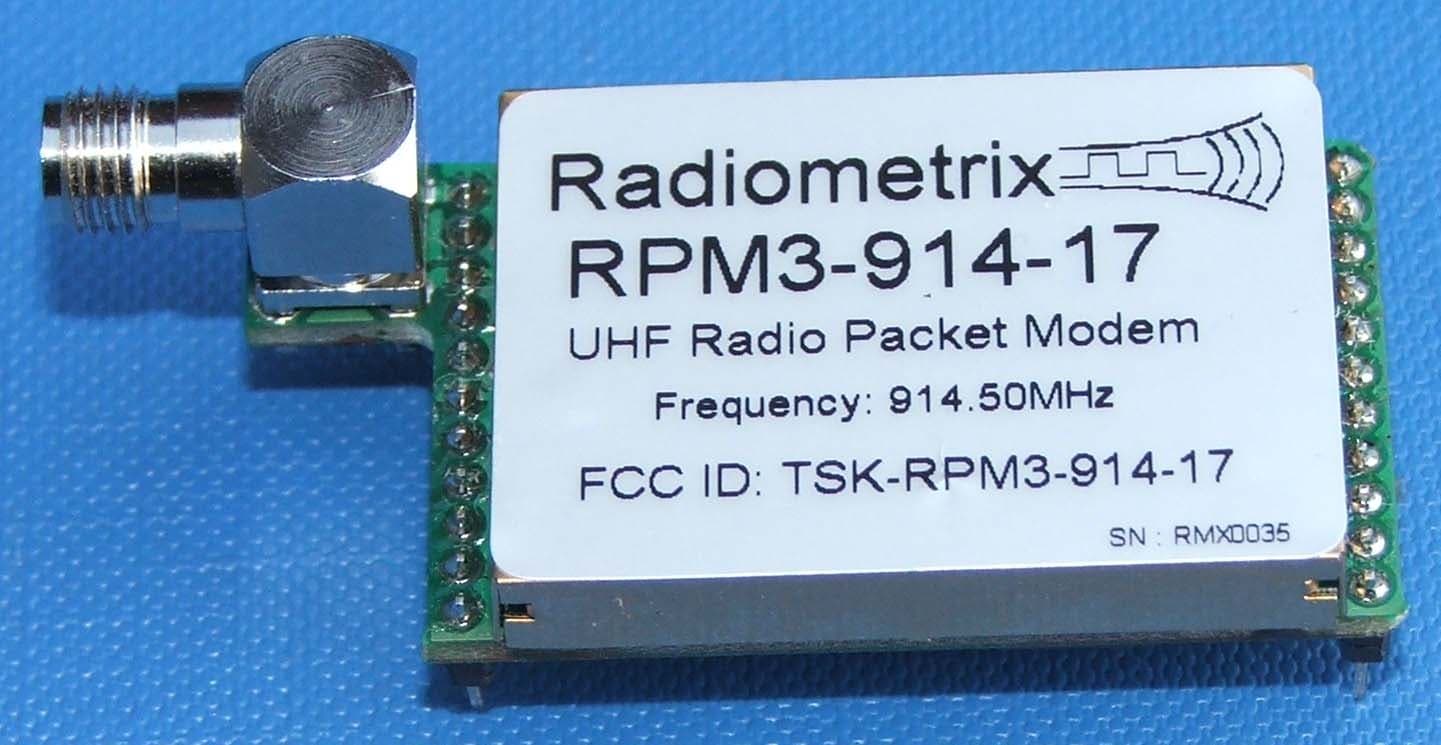
TSK-RPM3-914-17
Dec 20, 2005RPM3-914-17-ANT UHF Radio Packet Modem
Equipment Class
DXT - Part 15 Low Power Transceiver, Rx Verified