TSK-RPM3-914-17RPM3-914-17-ANT UHF Radio Packet Modem
Radiometrix Limited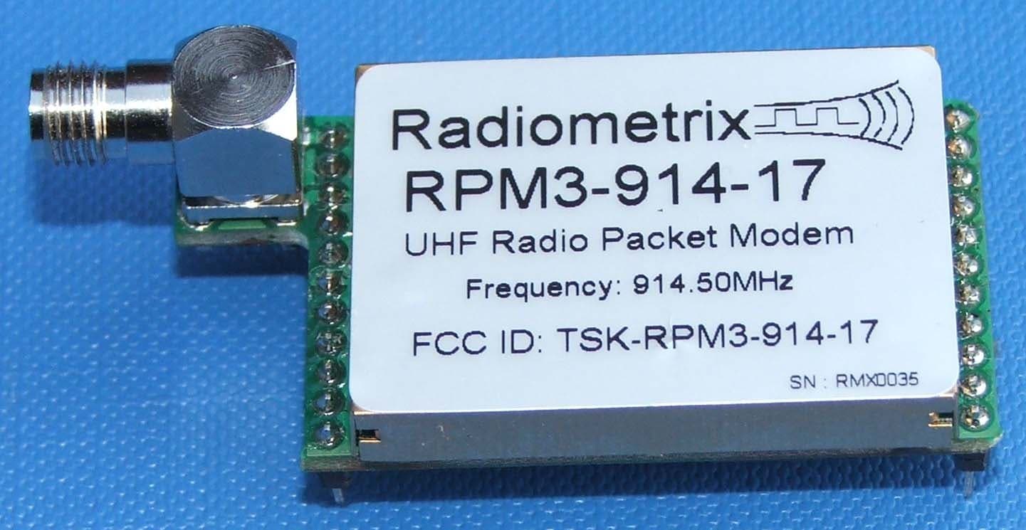
Click to zoom
Application Details
- Equipment Class
- DXT - Part 15 Low Power Transceiver, Rx Verified
- Date of Grant
- Dec 20, 2005
- Application Purpose
- Original Equipment
- Date of Application
- Dec 20, 2005
- Equipment Note
- RPM3-914-17-ANT UHF Radio Packet Modem
- Frequency Range
- 914.50000000 - 914.50000000
- Company
- Radiometrix Limited
- Country
- United Kingdom
Documents & Files
Document Text
Text extracted from the exhibit documents filed with the FCC. Open a document above to read the original.
Users Manual
Radiometrix Ltd. UHF FM Radio Packet Modem page 1 The UHF Radio Packet Modem (RPM3) is a low cost intelligent radio packet modem that enables a two way radio network/link to be simply implemented between a number of digital devices. The RPM3 uses addressable data packets with error checking, packet acknowledgements and retransmissions to achieve a reliable transparent wireless data link. Built for ease of use and rapid installation, the serial interface ensures direct connection to microprocessors or to RS232 port via RS232 driver while remote configuration enables post installation setup of the modem. Features Addressable point-to-point Point-to-Multipoint and broadcast modes Inverted RS232 interface at 5V or 3VCMOS level DTE speed 600-115200bps Overall throughput: 17kbps with ACK 28kbps without ACK Single 5V or 3V supply 15mA during data streaming at maximum rate Flow control – Hardware (CTS), None Available in 869.85MHz (EU), 914.50MHz (North America) Usable range up to 200m (650ft.) No Duty Cycle Restriction Built-in command line configuration Built-in RF link diagnostics Remote over-air unit configuration Low operating current, Auto standby mode Conforms to European ETSI EN 300 220-3 and EN 301 489-3 Conforms to FCC Part 15.249 Dimensions: 39mm X 23mm X 10mm Applications Telemetry and telecontrol EPOS equipment, barcode scanners, belt clip printers, stock control, job allocation Remote data acquisition system, data loggers In-building, environmental monitoring and control systems High-end security and alarm signalling Automated Monitoring and Control Systems Fleet management, vehicle data acquisition UHF Radio Packet Modem Radiometrix Hartcran House, 231 Kenton Lane, Harrow, HA3 8RP, England 29 November 2005 RPM3 N EW Tel: +44 (0) 20 8909 9595, Fax: +44 (0) 20 8909 2233 Figure 1: RPM3-914-17 Radiometrix Ltd. UHF FM Radio Packet Modem page 2 INTRODUCTION The RPM3 is a self-contained Radio Packet Modem module that requires only a simple antenna, 5V supply and a serial I/O port on a host microcontroller or PC. The module provides all the RF circuits and processor intensive low level packet formatting and packet recovery functions required to inter-connect any number of devices with serial port in a radio network. A continuous stream of serial data downloaded by a Host microcontroller into the RPM3 serial receive buffer is transmitted by the RPM3’ S transceiver and will "appear" in the serial buffer of the addressed RPM3 within radio range. Figure 2: Point to point wireless link with RPM3 + Host microcontroller 1. FUNCTIONAL DESCRIPTION The RPM3 is a connection oriented modem module for sending and receiving serial data via an RF communications link. The RPM3 handles all necessary protocol related functions of validation and retries to ensure error free and uninterrupted data is sent over the communications link. All data transfers between a pair of RPM S are fully acknowledged, thus preventing the loss of data. Bit coding and checksums are used on the data packets to ensure the validity of the received data at the remote end. Figure 3: RPM3 block diagram Radiometrix Ltd. UHF FM Radio Packet Modem page 3 1.1 OPERATING STATES The R ADIO PACKET MODEM has three normal operating states: • S HUTDOWN • S TANDBY • C ONNECTED S HUTDOWN The S HUTDOWN state is entered by asserting the WAKE/DTR input pin high (Vcc). It effectively forces the RPM3 into a suspended state. Communications cannot be made with the RPM3 in this state. WAKE/DTR pin should be pulled Low by host or connected to 0V to Enable the RPM3. S TANDBY Immediately after power up and during normal operation, the RPM3 will automatically enter standby mode where it is waiting for a connection request from a remote RPM3 module. While in this mode a remote connection request can be received which will place the RPM3 into a connected state allowing it to then start receiving data from the remote unit. The connected host device can also send data to the RPM3 via the serial interface which will force the module to send a connection request to the remote RPM3 module, thus effectively setting up a logical connection between two units and allowing data to be transferred. C ONNECTED On receipt of a connection request from a remote unit, the RPM3 immediately enters a connected state. This effectively allows the RPM3 modems to start sending and receiving data. In-coming data is sent to the host via the serial port in the same form as it was given to the remote RPM3 module. Figure 4: RPM3 transmitting data at 28kbps during ZMODEM file transfer to a remote RPM3 Radiometrix Ltd. UHF FM Radio Packet Modem page 4 2 The Host Interface 2.1 SIGNALS The connection to the RPM3 is a full duplex serial interface supporting baud rates from 600bps to 115200bps. Additional control signals are provided to assist in flow control, configuration and power saving in the RPM3. Figure 5: Physical dimensions and pinouts Pin name Pin Pin Function In/Out Description RF GND 1, 3 RF signal ground BNC casing/coax braid connection RF 2 RF signal Input or Output Antenna pin/coax core connection RXSELCT 4 Receiver Select Input or Output Internal RF Receiver Enable to BiM3A or RF Receiver Active Indicator TX SELECT 5 Transmitter Select Input or Output Internal RF Transmitter Enable to BiM3A or RF Transmitter Active Indicator TXD/AF 7 Transmitted Data or demodulated signal Input or Output Transmitted Packetised Data to BiM3A Analogue Demodulated signal from BiM3A D3 8 FRPC Data line NC Internal data line between RPM and FRPC D2 9 FRPC Data line NC Internal data line between RPM and FRPC SIGNAL 10 Preamble Detect Output Valid preamble indicator RST 11 FRPC reset NC Resets FRPC which also isolates BiM3A RXA 12 Receive Acknowledge NC RPM to FRPC download Request Acknowledge RXR 13 Receive Request Output Valid Data packet indicator RESET 14 Reset Input Hardware reset of the RPM3 SETUP 15 Enter Setup Input Enter RPM3 configurator after a RESET WAKE/DTR 16 Wake or Shutdown Input Wakes …
Text truncated - open the document above for the full version.
Block Diagram
AF RXD Mixer IF Amp Demod RSSI 10.7MHz 869/914MHz bpf data slicer buffer φ ÷ 64 Loop Filter LPF 35kHz LPF TXD ref osc 32 ÷ Loop Filter ref osc φ V C O V C O matching & lpf preamp Tx/Rx switch Regulator & Tx/Rx logic Tx select Rx select Antenna Vcc 28.24375MHz 14.2899MHz
Cover Letter(s)
Friday, 25 November 2005 Telecommunication Certification Body RFI Global Services Ltd. Pavilion A Ashwood Park Basingstoke Hampshire RG23 8BG United Kingdom Subject: Certification Application FCC ID: TSK-RPM3-914-17 It is requested that the following information is to be held confidential on behalf of Radiometrix Limited. FCC Rules Part 0.459 refers. Exhibit No. of files No. of pages/file BiM3A_schematics.pdf 1 1 bim3a_bom.zip 1 3 Schematics and Parts List (BoM) contain commercially sensitive information. We have developed and employed certain circuit and PCB layout techniques in the design of this unit which we regard as our own Intellectual Property (IP) and which must therefore remain confidential and not subject to public access. Specifically, we will not divulge any information about the design which would allow a competitor to reproduce it or reverse-engineer it more easily thus giving them an unwarranted competitive advantage. Such information specifically to include the schematic and parts list, and any information which is not already contained in, or can be inferred from, our publicly-available datasheet or even using datasheets, application notes, reference designs, etc of the RF IC manufacturer. Yours sincerely Sabananthan Paramananthan Technical Manager
Cover Letter(s)
Monday, 28 November 2005 Equipment Authorization Branch Federal Communications Commission 445 12th Street SW Washington, DC 20554 USA To whom it may concern, PART 15 Unlicensed Modular Transceiver Approval for RPM3-914-17-ANT We would like to apply for Modular Transceiver Approval for RPM3-914-17-ANT which has been verified to comply with relevant FCC rules by RFI Global Services Ltd (RFI) which is an accredited Telecommunication Certification Body (TCB) RPM3-914-17-ANT is a complete RF transceiver module. It has its own crystal controlled Phase Locked Loop (PLL) synthesiser with Voltage Controlled Oscillator (VCO) and antenna coupled to the module using unique Reverse Polarity SMA connector. It just requires power supply and serial data. RPM3 uses BiM3A RF transceiver which has its own RF shielding can. Module has restricted data input baud rates from 600bps to 115200bps with internal microcontroller modulating the carrier with a maximum of 64kbps bit rate. BiM3A transceiver in RPM3 has its own internal voltage regulator to provide constant 2.8V supply to internal RF circuit. RPM3-914-17-ANT is a RPM3-914-17-RPS with Reverse Polarity SMA (RPSMA) connector coupled to a ¼ wavelength monopole antenna with another unique RPSMA connector. RPM3 complied with the AC line conducted requirements of Part 15.207 in stand-alone configuration. Required FCC Labelling is described clearly on the data sheet for the RPM3. RPM3-914-17-ANT using BiM3A-914-64 transceiver complies with FCC Part 15.249 with the Electric Field Strength of 43.7mV/m (50mV/m is the limit). As the Electric Field Strength at 3m for the module is lower than 50mV/m, RF exposure requirement may not apply. However, end-user must take necessary precaution so that the final product complies with RF Exposure requirement. Both Transmitter and Receiver portion are verified to comply with FCC Part 15 requirement. Yours truly, Sabananthan Paramananthan Technical Manager
Operational Description
TSK-RPM3-914-17 OPERATIONAL DESCRIPTION The UHF Radio Packet Modem (RPM3) is a low cost intelligent radio packet modem that enables a two way radio network/link to be simply implemented between a number of digital devices. The RPM3 uses addressable data packets with error checking, packet acknowledgements and retransmissions to achieve a reliable transparent wireless data link. Built for ease of use and rapid installation, the serial interface ensures direct connection to microprocessors or to RS232 port via RS232 driver while remote configuration enables post installation setup of the modem. RPM3 uses BiM3A (64kbps UHF Wide Band FM) transceiver for its RF interface.
Test Report
TEST REPORT FROM RFI GLOBAL SERVICES LTD Test of: Radiometrix Ltd. RPM3-914-17-ANT. To: FCC Part 15.249 Test Report Serial No: RFI/MPTE3/RP47441JD01A Supersedes Test Report Serial No: RFI/MPTE2/RP47441JD01A This Test Report Is Issued Under The Authority Of Andrew Brown, Operations Manager: Tested By: Raul Recio Checked By: Steven Wong Report Copy No: PDF01 Issue Date: 15 December 2005 Test Dates: 22 September 2005 to 21 October 2005 and 02 December 2005 This report is issued in Adobe Acrobat portable document format (PDF). It is only a valid copy of the report if it is being viewed in PDF format with the following security options not allowed: Changing the document, Selecting text and graphics, Adding or changing notes and form fields. This report may be copied in full. The results in this report apply only to the sample(s) tested. RFI GLOBAL SERVICES LTD TEST REPORT S.No. RFI/MPTE3/RP47441JD01A Page 2 of 40 Issue Date: 15 December 2005 Test of: Radiometrix Ltd. RPM3-914-17-ANT. To: FCC Part 15.249 This page has been left intentionally blank. RFI GLOBAL SERVICES LTD TEST REPORT S.No. RFI/MPTE3/RP47441JD01A Page 3 of 40 Issue Date: 15 December 2005 Test of: Radiometrix Ltd. RPM3-914-17-ANT. To: FCC Part 15.249 Table of Contents 1. Client Information ............................................................................................................................4 2. Equipment Under Test (EUT) ..........................................................................................................5 3. Test Specification, Methods and Procedures ...............................................................................8 4. Deviations from the Test Specification..........................................................................................9 5. Operation of the EUT During Testing...........................................................................................10 6. Summary of Test Results ..............................................................................................................11 7. Measurements, Examinations and Derived Results ...................................................................12 8. Measurement Methods ..................................................................................................................32 9. Measurement Uncertainty .............................................................................................................35 Appendix 1. Test Equipment Used ...................................................................................................36 Appendix 2. Test Configuration Drawings.......................................................................................37 Test Report Serial No: RFI/MPTE3/RP47441JD01A Supersedes Test Report Serial No: RFI/MPTE2/RP47441JD01A RFI GLOBAL SERVICES LTD TEST REPORT S.No. RFI/MPTE3/RP47441JD01A Page 4 of 40 Issue Date: 15 December 2005 Test of: Radiometrix Ltd. RPM3-914-17-ANT. To: FCC Part 15.249 1. Client Information Company Name: Radiometrix Ltd. Address: Hartcran House 231 Kenton Lane Harrow Middlesex HA3 8RP Contact Name: Mr S. Paramananthan RFI GLOBAL SERVICES LTD TEST REPORT S.No. RFI/MPTE3/RP47441JD01A Page 5 of 40 Issue Date: 15 December 2005 Test of: Radiometrix Ltd. RPM3-914-17-ANT. To: FCC Part 15.249 2. Equipment Under Test (EUT) The following information (with the exception of the Date of Receipt) has been supplied by the client: 2.1. Identification of Equipment Under Test (EUT) Brand Name: Radiometrix Model Name or Number: RPM3-914-17-ANT Unique Type Identification: Not Stated Serial Number: 0021 Country of Manufacture: UK FCC ID: TSK-RPM3-914-17 Date of Receipt: 15 September 2005 2.2. Accessories The following accessories were supplied with the EUT: Description: Carrier Board Brand Name: Radiometrix Model Name or Number: SpacePort Modem Evaluation Kit Serial Number: 65535 Cable Length and Type: Not Applicable Connected to Port: EUT Soldered on Board Description: Antenna Brand Name: Not Stated Model Name or Number: RPSMA ¼ Wavelength Monopole Serial Number: Not Applicable Cable Length and Type: Not Applicable Connected to Port: Reverse Polarity SMA Connector Description: RS232 Serial Cable Brand Name: Not Stated Model Name or Number: Not Stated Serial Number: Not Stated Cable Length and Type: 1.75m / RS232 Serial Connected to Port: RS232 Serial Port RFI GLOBAL SERVICES LTD TEST REPORT S.No. RFI/MPTE3/RP47441JD01A Page 6 of 40 Issue Date: 15 December 2005 Test of: Radiometrix Ltd. RPM3-914-17-ANT. To: FCC Part 15.249 2.3. Description of EUT The equipment under test is a Radio Packet Modem with integrated low Power Radio Transceiver, Fast Radio Packet Controller and Radio Packet Modem Controller. The device uses addressable data packets with error checking, packet acknowledgements and retransmissions to achieve a reliable transparent wireless data link. 2.4. Modifications Incorporated in the EUT Two capacitors were changed on the output matching network of the EUT to reduce the power at the fundamental frequency. The EUT was re-tested after the modification. RFI GLOBAL SERVICES LTD TEST REPORT S.No. RFI/MPTE3/RP47441JD01A Page 7 of 40 Issue Date: 15 December 2005 Test of: Radiometrix Ltd. RPM3-914-17-ANT. To: FCC Part 15.249 2.5. Additional Information Related to Testing Power Supply Requirement: Internal battery supply of 9V to the test board. The EUT is powered by a regulated supply of 5 V DC from the test board. Intended Operating Environment: Residential, Commercial, Light Industry and Heavy Industry Equipment Category: Short Range (Low Power) Type of Unit: Base Station (Fixed Use) Portable (Standalone battery powered device) Interface Ports: Antenna Port – Reverse SMA Polarity Transmit Frequency Range: 902 MHz to 928 MHz Channel ID Channel Number Channel Frequency (MHz) Transmit Channels Tested: Single Channel Not Applicable 914.5 Highest Unintentionally Generated Frequency: 914.5 MHz Receive Frequency Range: 902 MHz to 9…
Text truncated - open the document above for the full version.
Contact Information
Applicant
Ken Kangeyan(Mr)
Technical Contact
RADIOMETRIX LIMITEDSABANANTHAN PARAMANANTHAN
[email protected]+44 20 8909 9595
HARTCRAN HOUSE · HARROW · United Kingdom
Non-Technical Contact
RADIOMETRIX LIMITEDKEN KANGEYAN
Test Firm
RFI Global Services Ltd.Allan Hume
Technical Specifications
| # | Rule Parts | Frequency Range | Power Output |
|---|---|---|---|
| 1 | 15C | 914.5 MHz - 914.5 MHz | - |
Other Applications from Radiometrix Limited
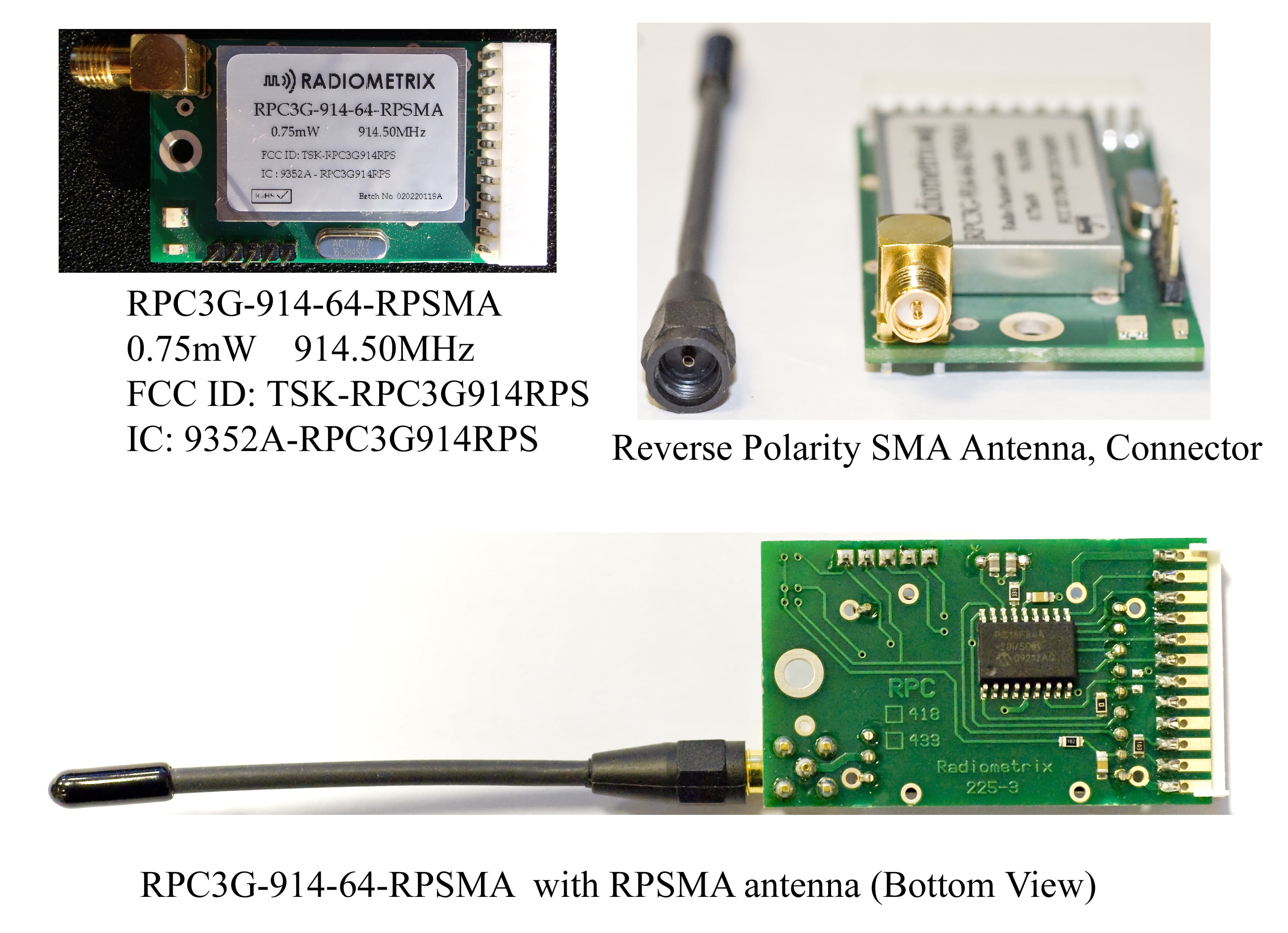
TSK-RPC3G914RPS
Aug 02, 2011Radio Packet Controller Module.
Equipment Class
DXT - Part 15 Low Power Transceiver, Rx Verified