TTE3625Booster
Suzhou Sate Auto Electronic Co., Ltd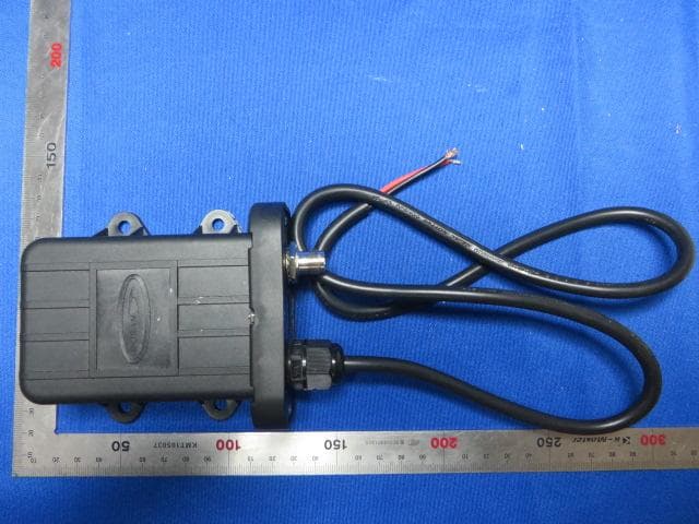
Click to zoom
Application Details
- Equipment Class
- DSR - Part 15 Remote Control/Security Device Transceiver
- Date of Grant
- May 05, 2014
- Application Purpose
- Original Equipment
- Date of Application
- May 05, 2014
- Equipment Note
- Booster
- Frequency Range
- 434.10000000 - 434.10000000
- Country
- China
Documents & Files
Document Text
Text extracted from the exhibit documents filed with the FCC. Open a document above to read the original.
Users Manual
SMART BOOSTER User Manual The smart booster is used to transmit the signal of transmitter and magnified it. Then transmit it to the monitor. The smart booster can match the different monitors automatically. In order to ensure good communication, please choose a suitable location for it on the beam of the vehicle bottom. The location should be near the middle of the vehicle bottom. 1. Fix the booster onto rubber plate with 4 screws with diameter of 6mm. 2. Fix rubber plate and triangle together with 2 screws with diameter of 6mm. 3. Drain 2 holes with diameter of 6mm on the beam of the vehicle bottom according to the installation holes in triangle and then fix the booster with the screws. As shown below: Smart Booster Method1. Perpendicular to the beam of the vehicle bottom Mothod2. Parallel to the beam of the vehicle bottom Note: The side with power wire face up. 4. The smart booster with 3 power wires. Connect brown power wire with positive of vehicle’s continuous power supply, blue wire with the positive of ignition switch, the bule wire have 12V power supply only when the ignition switch is powered. Connect the yellow and green wire to ground. Then fix the power wires with nylon strips. beam triangle Power wire of smart booster 5. Indicator light explanation Three red LED lights in the transparent window of smart booster, from left to right: power indicator, transmitting indicator and receiving indicator light. As shown below: Connect ground Connect positive of 12V/24V contiuous power supply Connect positive of ignition switch power indicator IMPORTANT NOTES: 1. Smart booster should be installed in the free space properly. 2. If there isn’t a proper position in the middle bottom of vehicle, user can install it in the side of vehicle. 3. In order to ensure good communication of smart booster, please don't conjoint the smart booster to the metal directly. 4. The power wires should be fixed with nylon strips to prevent them being frazzling and short circuit. 5. Ensure the input voltage is accordant with smart booster voltage. Connect the power wires according to marked positive and negative wire. 6. Please connect a 2A waterproof fuse at the position of smart booster connect the continuous power supply of vehicle to ensure the safety of circuitry. Specifications: Modulation Type: FSK Mid-frequency: 434.1 MHz Receiving Sensitivity: -105 dBm Input Voltage: 12V / 24V Operating Temperature: -40°C~+85°C Storage Temperature: -30°C~75°C Federal Communications Commission (FCC) Interference Statement This device complies with Part 15 of the FCC Rules. Operation is subject to the following two conditions: (1) This device may not cause harmful interference, and (2) this device must accept any interference received, including interference that may cause undesired operation. FCC Caution: Any changes or modifications not expressly approved by the party responsible for compliance could void the user’s authority to operate this equipment. RF exposure warning This equipment complies with FCC radiation exposure limits set forth for an uncontrolled environment.
Cover Letter(s)
Suzhou Sate Auto Electronic Co., Ltd. ----------------------------------------------------------------------------------------------------------------------------------- April 21, 2014 Federal Communications Commission Authorization and Evaluation Division Confidentiality Request regarding application for certification of FCC ID: TTE3625. Pursuant to Sections 0.457 and 0.459 of the Commission’s Rules, we hereby request confidential treatment of information accompanying this application as outlined below: Exhibit Type File Name Block Diagram TTE3625_FCC_BlcokDiagram.pdf Schematic Diagram TTE3625_FCC_SchematicDiagram.pdf Circuit Description TTE3625_FCC_OperationalDescription.pdf The above materials contain trade secrets and proprietary information not customarily released to the public. The public disclosure of these materials may be harmful to the applicant and provide unjustified benefits to its competitors. Yours Sincerely, Suzhou Sate Auto Electronic Co., Ltd. Signature: Zheng Yong / G.M.
External Photos
1 of 3 External Photo (1) EUT Photo (2) EUT Photo (3) EUT Photo (4) EUT Photo (5) EUT Photo (6) EUT Photo
ID Label/Location Info
FCC ID Label Specifications: Text is Black in color and justified. Label are printed in indelible ink on permanent adhesive silk-screened onto the EUT or shall be affixed at a conspicuous location on the EUT. FCC ID Label Location FCC ID: TTE3625 This device complies with Part 15 of the FCC Rules. Operation is subject to the following two conditions: (1) This device may not cause harmful interference, and (2) This device must accept any interference received, including interference that may cause undesired operation.
Internal Photos
1 of 4 Internal Photo (1) EUT Photo (2) EUT Photo (3) EUT Photo (4) EUT Photo (5) EUT Photo (6) EUT Photo (7) EUT Photo (8) EUT Photo
Test Report
MRT Technology (Suzhou) Co., Ltd Report No.: 1404RSU01301 Phone: +86-512-66308358 Report Version: V01 Fax: +86-512-66308368 Issue Date: 05-05-2014 Web: www.mrt-cert.com FCC ID: TTE3625 Page Number: 1 of 26 FCC ID: TTE3625 APPLICANT: Suzhou Sate Auto Electronic Co., Ltd. Application Type: Certification Product: Booster Brand Name: SATE Model No.: #3625, TBS03-DL, TBS03-D1L, 360PR, TBS09 FCC Classification: FCC Part 15 Remote Control/Security Device Transmitter(DSR) FCC Rule Part(s): Part 15.231(e) Test Procedure(s): ANSI C63.10-2009 Test Date: April 15 ~ 27, 2014 MEASUREMENT REPORT FCC PART 15.231(e) Reviewed By : ( Robin Wu ) Approved By : ( Marlin Chen ) The test results relate only to the samples tested. This equipment has been shown to be capable of compliance with the applicable technical standards as indicated in the measurement report and was tested in accordance with the measurement procedures specified in ANSI C63.10-2009. Test results reported herein relate only to the item(s) tested. The test report shall not be reproduced except in full without the written approval of MRT Technology (Suzhou) Co., Ltd. Report No.: 1404RSU01301 FCC ID: TTE3625 Page Number: 2 of 26 Revision History Report No. Version Description Issue Date 1404RSU01301 Rev. 01 Initial report 05-05-2014 Report No.: 1404RSU01301 FCC ID: TTE3625 Page Number: 3 of 26 CONTENTS Description Page 1. INTRODUCTION ..................................................................................................................... 6 1.1. Scope ........................................................................................................................... 6 1.2. MRT Test Location ....................................................................................................... 6 2. PRODUCT INFORMATION ..................................................................................................... 7 2.1. Equipment Description .................................................................................................. 7 2.2. Test Standards ............................................................................................................. 8 2.3. Test Methodology ......................................................................................................... 8 2.4. EUT Setup and Test Mode ........................................................................................... 8 3. ANTENNA REQUIREMENTS .................................................................................................. 9 4. TEST EQUIPMENT CALIBRATION DATA ............................................................................ 10 5. MEASUREMENT UNCERTAINTY .......................................................................................... 11 6. TEST RESULT ...................................................................................................................... 12 6.1. Summary .................................................................................................................... 12 6.2. Radiated Emissions .................................................................................................... 13 6.2.1. Standard Applicable ................................................................................................ 13 6.2.2. Test Procedure........................................................................................................ 13 6.2.3. Test Setup ............................................................................................................... 14 6.2.4. Test Results ............................................................................................................ 15 6.3. 20dB Bandwidth ......................................................................................................... 19 6.3.1. Standard Applicable ................................................................................................ 19 6.3.2. Test Procedure........................................................................................................ 19 6.3.3. Test Setup ............................................................................................................... 19 6.3.4. Test Result .............................................................................................................. 20 6.4. Transmission Time ...................................................................................................... 21 6.4.1. Standard Applicable ................................................................................................ 21 6.4.2. Test Procedure........................................................................................................ 21 6.4.3. Test Setup ............................................................................................................... 21 6.4.4. Test Result .............................................................................................................. 22 6.5. Duty Cycle .................................................................................................................. 24 6.5.1. Standard Applicable ................................................................................................ 24 6.5.2. Test Procedure........................................................................................................ 24 6.5.3. Test Setup ............................................................................................................... 24 6.5.4. Test Result .............................................................................................................. 25 Report No.: 1404RSU01301 FCC ID: TTE3625 Page Number: 4 of 26 7. CONCLUSION ....................................................................................................................... 26 Report No.: 1404RSU01301 FCC ID: TTE3625 Page Number: 5 of 26 §2.1033 General Information Applicant: Suzhou Sate Auto Electronic Co., L…
Text truncated - open the document above for the full version.
Test Setup Photos
1 of 1 RF Test Setup Photo Description: Radiated Emission Test Setup for 30MHz ~ 1GHz Description: Radiated Emission Test Setup for 1GHz ~ 18GHz
Contact Information
Applicant
Justin Jia(G. M. of R & D)
Test Firm
MRT Technology (Suzhou) Co., LtdWu Jian
[email protected]86-512-66308358
Technical Specifications
| # | Rule Parts | Frequency Range | Power Output |
|---|---|---|---|
| 1 | 15.231 | 434.1 MHz - 434.1 MHz | - |
Other Applications from Suzhou Sate Auto Electronic Co., Ltd
TTE403112ZG1A
Jul 20, 2026Tire pressure sensor
Equipment Class
DSC - Part 15 Security/Remote Control Transmitter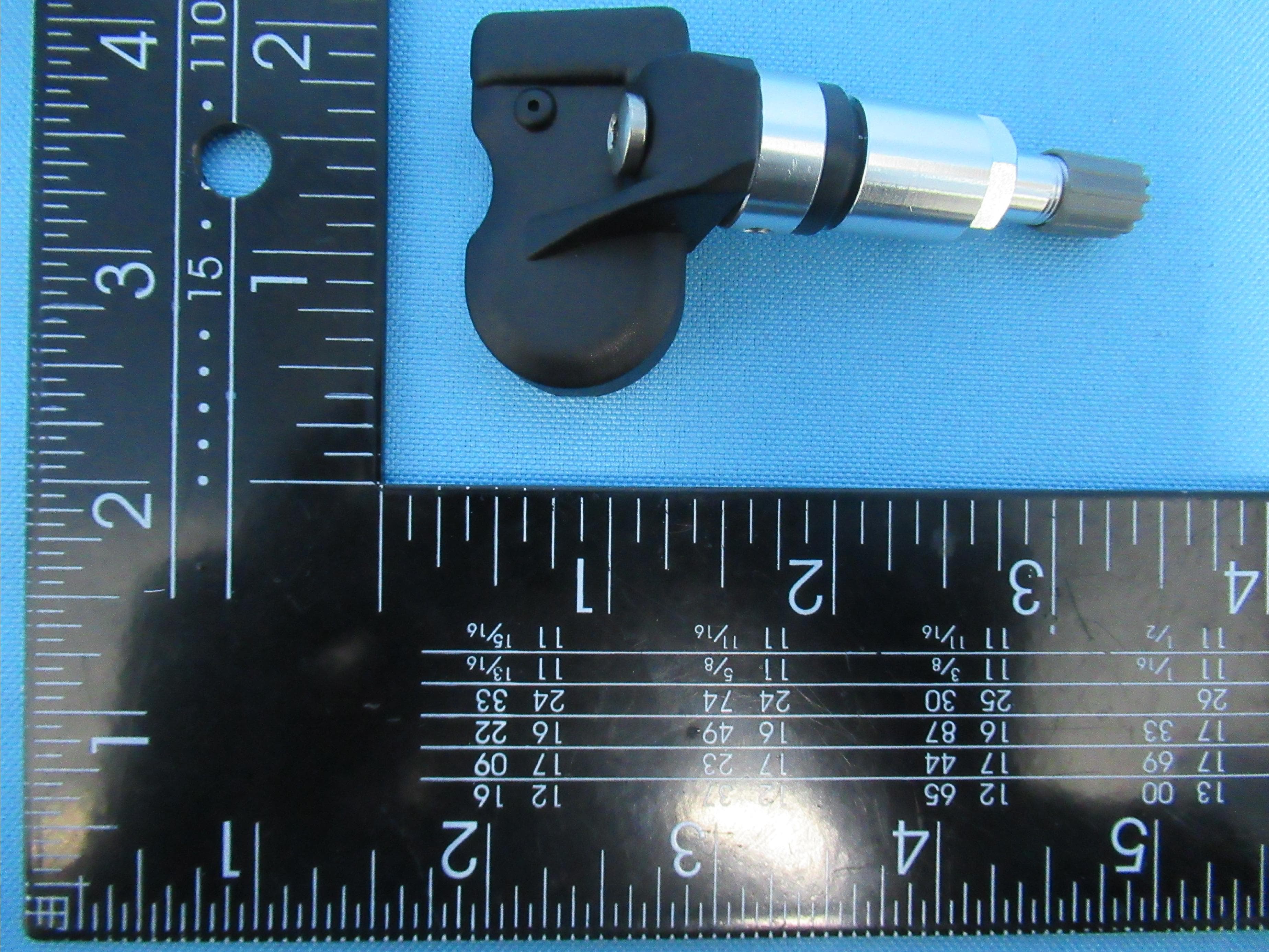
TTETSB60
Apr 14, 2021Tire Pressure Monitoring System Sensor
Equipment Class
DSC - Part 15 Security/Remote Control Transmitter
TTE-TSB44
Jul 15, 2015Tire Pressure Monitoring System
Equipment Class
DSC - Part 15 Security/Remote Control Transmitter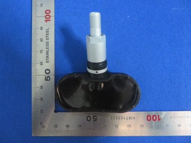
TTE-TSB41
Jul 12, 2015Tire Pressure Monitoring System
Equipment Class
DSC - Part 15 Security/Remote Control Transmitter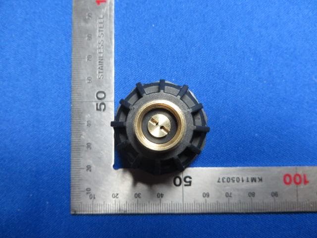
TTETSE30
May 05, 2014TYRE PRESSURE MONITORING SYSTEM
Equipment Class
DSC - Part 15 Security/Remote Control Transmitter