TTETSE30TYRE PRESSURE MONITORING SYSTEM
Suzhou Sate Auto Electronic Co., Ltd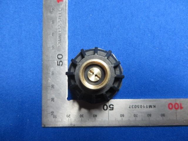
Click to zoom
Application Details
- Equipment Class
- DSC - Part 15 Security/Remote Control Transmitter
- Date of Grant
- May 05, 2014
- Application Purpose
- Original Equipment
- Date of Application
- May 05, 2014
- Equipment Note
- TYRE PRESSURE MONITORING SYSTEM
- Frequency Range
- 434.10000000 - 434.10000000
- Country
- China
Documents & Files
Document Text
Text extracted from the exhibit documents filed with the FCC. Open a document above to read the original.
Users Manual
Tyre Pressure Monitoring System (TSE30) User Manual Before install the transmitter, make sure the transmitter has been programmed into the monitor, which is under normal mode. If the transmitter are not programmed or programmed but didn't receive the signal, the screen display “NSP”. When the transmitter is screwed onto the valve according to the programmed position, the monitor can receive the signals and then display the transmitter location icon, pressure, temperature information on the screen. When all of information were received by the monitor and the information are all normal, the screen display “ON”. Tranmitter Installation Steps 1. Remove the current tire valve cap. 2. Inflate the tire to the standard pressure recommended by the manufacturer or pressure needed by the user. 3. Screw the transmitter onto the tire valve. 4. Check the connection of Transmitter and valve with the soap solution to confirm whether the transmitter is firmly screwed onto the valve or not, check whether there is air leakage caused by the installation or the seal of the Transmitters or not. 5. Once screwed onto the tire, transmitter can sense the pressure inside the tire and transmit the data to the monitor, and the information will appear on the screen within 6 minutes. Note: 1. Please set the standards pressure of each tire on monitor before install the transmitter. The standard pressure has been set to100PSI in factory. 2. If one of your transmitters is broken or lost, the user only needs to replace it, others will work as normal. Programming of Transmitter ID When the Monitor is powered for the first time, the screen shows “NSP”, which means there is no transmitter programmed into it. If the user wants to program a new transmitter into the Monitor, the operation should be finished in programming mode. At this time, make sure the transmitter to be programmed has not been screwed onto the valve yet until the programming has been finished and the Monitor returns to normal mode. Each transmitter has 4 groups of ID, for example when program the transmitter with ID of 001 001 001 158 to front right tire position, the user only needs to input the last 3 digits “158”. Monitor will record the rest 3 groups of ID automatically. 1. After powered the Monitor and the screen displays “NSP”, press P for 3 seconds to access the system programming mode, the first interface is for ID programming as shown below: 2. Press any of the four arrow keys to choose the transmitter position which needs to be programmed. 3. Then press S for 3 seconds to start programming and the digit flashes, then press up or down arrow key to adjust the value. 4. Once finish programming of the first digit, press → to start programming the second digit which flashes. Press up or down arrow key to adjust the value. 5. Press → again to program the third digit which flashes. Press up or down arrow key to adjust the value. 6. When finish programming these 3 digits, press S for 3 seconds to save with the screen flashes twice, beep buzzes twice. Then it will automatically switch to next tire position. 7. Follow the above operations to program ID of other transmitters. Transmitter Modulation Type: FSK Mid-frequency: 434.1 MHz Transmitting Power: 0 dBm Input Voltage: 3.6V (Battery) Static Current: < 0.7uA Operating temperature range: -40°C~125°C Storage temperature range: -40°C~125°C Transmitter weight: 25 g Federal Communications Commission (FCC) Interference Statement This device complies with Part 15 of the FCC Rules. Operation is subject to the following two conditions: (1) This device may not cause harmful interference, and (2) this device must accept any interference received, including interference that may cause undesired operation. FCC Caution: Any changes or modifications not expressly approved by the party responsible for compliance could void the user’s authority to operate this equipment. RF exposure warning This equipment complies with FCC radiation exposure limits set forth for an uncontrolled environment.
Cover Letter(s)
Suzhou Sate Auto Electronic Co., Ltd. ----------------------------------------------------------------------------------------------------------------------------------- Declaration of Authorization We Name: Suzhou Sate Auto Electronic Co., Ltd. Address: No.36 Building, Yangtai Road, Suzou Industrial Park, Suzhou, Jiangsu, P.R.China Declare that: Name Representative of agent: Wu Jian Agent Company name: MRT Technology (Suzhou) Co., Ltd Address: D8 Building, Youxin Industrial Park, No.2 Tian'edang Rd., Wuzhong Economic Development Zone, City: Suzhou Country China is authorized to apply for Certification of the following product(s): Product description: Tyre Pressure Monitoring System FCC ID: TTETSE30 Model: TSE30 on our behalf. Signature: Zheng Yong / G.M. Date: 2014-04-21
Cover Letter(s)
Suzhou Sate Auto Electronic Co., Ltd. ----------------------------------------------------------------------------------------------------------------------------------- April 21, 2014 Federal Communications Commission Authorization and Evaluation Division Confidentiality Request regarding application for certification of FCC ID: TTETSE30. Pursuant to Sections 0.457 and 0.459 of the Commission’s Rules, we hereby request confidential treatment of information accompanying this application as outlined below: Exhibit Type File Name Block Diagram TTETSE30_FCC_BlcokDiagram.pdf Schematic Diagram TTETSE30_FCC_SchematicDiagram.pdf Circuit Description TTETSE30_FCC_OperationalDescription.pdf The above materials contain trade secrets and proprietary information not customarily released to the public. The public disclosure of these materials may be harmful to the applicant and provide unjustified benefits to its competitors. Yours Sincerely, Suzhou Sate Auto Electronic Co., Ltd. Signature: Zheng Yong / G.M.
External Photos
1 of 2 External Photo (1) EUT Photo (2) EUT Photo (3) EUT Photo
ID Label/Location Info
FCC ID Label Specifications: Text is Black in color and justified. Label are printed in indelible ink on permanent adhesive silk-screened onto the EUT or shall be affixed at a conspicuous location on the EUT. FCC ID Label Location FCC ID: TTETSE30
Internal Photos
1 of 4 Internal Photo (1) EUT Photo (2) EUT Photo (3) EUT Photo (4) EUT Photo (5) EUT Photo (6) EUT Photo (7) EUT Photo (8) EUT Photo
Test Report
MRT Technology (Suzhou) Co., Ltd Report No.: 1404RSU01201 Phone: +86-512-66308358 Report Version: V01 Fax: +86-512-66308368 Issue Date: 05-05-2014 Web: www.mrt-cert.com FCC ID: TTETSE30 Page Number: 1 of 26 FCC ID: TTETSE30 APPLICANT: Suzhou Sate Auto Electronic Co., Ltd. Application Type: Certification Product: Tyre Pressure Monitoring System Model No.: TSE30 Brand Name: SATE FCC Classification: FCC Part 15 Security/Remote Control Transmitter(DSC) FCC Rule Part(s): Part 15.231(e) Test Procedure(s): ANSI C63.10-2009 Test Date: April 15 ~ 18, 2014 MEASUREMENT REPORT FCC PART 15.231(e) Reviewed By : ( Robin Wu ) Approved By : ( Marlin Chen ) The test results relate only to the samples tested. This equipment has been shown to be capable of compliance with the applicable technical standards as indicated in the measurement report and was tested in accordance with the measurement procedures specified in ANSI C63.10-2009. Test results reported herein relate only to the item(s) tested. The test report shall not be reproduced except in full without the written approval of MRT Technology (Suzhou) Co., Ltd. Report No.: 1404RSU01201 FCC ID: TTETSE30 Page Number: 2 of 26 Revision History Report No. Version Description Issue Date 1404RSU01201 Rev. 01 Initial report 05-05-2014 Report No.: 1404RSU01201 FCC ID: TTETSE30 Page Number: 3 of 26 CONTENTS Description Page 1. INTRODUCTION ..................................................................................................................... 6 1.1. Scope ........................................................................................................................... 6 1.2. MRT Test Location ....................................................................................................... 6 2. PRODUCT INFORMATION ..................................................................................................... 7 2.1. Equipment Description .................................................................................................. 7 2.2. Test Standards ............................................................................................................. 8 2.3. Test Methodology ......................................................................................................... 8 2.4. EUT Setup and Test Mode ........................................................................................... 8 3. ANTENNA REQUIREMENTS .................................................................................................. 9 4. TEST EQUIPMENT CALIBRATION DATA ............................................................................ 10 5. MEASUREMENT UNCERTAINTY .......................................................................................... 11 6. TEST RESULT ...................................................................................................................... 12 6.1. Summary .................................................................................................................... 12 6.2. Radiated Emissions .................................................................................................... 13 6.2.1. Standard Applicable ................................................................................................ 13 6.2.2. Test Procedure........................................................................................................ 13 6.2.3. Test Setup ............................................................................................................... 14 6.2.4. Test Results ............................................................................................................ 15 6.3. 20dB Bandwidth ......................................................................................................... 19 6.3.1. Standard Applicable ................................................................................................ 19 6.3.2. Test Procedure........................................................................................................ 19 6.3.3. Test Setup ............................................................................................................... 19 6.3.4. Test Result .............................................................................................................. 20 6.4. Transmission Time ...................................................................................................... 21 6.4.1. Standard Applicable ................................................................................................ 21 6.4.2. Test Procedure........................................................................................................ 21 6.4.3. Test Setup ............................................................................................................... 21 6.4.4. Test Result .............................................................................................................. 22 6.5. Duty Cycle .................................................................................................................. 24 6.5.1. Standard Applicable ................................................................................................ 24 6.5.2. Test Procedure........................................................................................................ 24 6.5.3. Test Setup ............................................................................................................... 24 6.5.4. Test Result .............................................................................................................. 25 Report No.: 1404RSU01201 FCC ID: TTETSE30 Page Number: 4 of 26 7. CONCLUSION ....................................................................................................................... 26 Report No.: 1404RSU01201 FCC ID: TTETSE30 Page Number: 5 of 26 §2.1033 General Information Applicant: Suzhou Sate Auto Electronic Co., Ltd. Applican…
Text truncated - open the document above for the full version.
Test Setup Photos
1 of 1 RF Test Setup Photo Description: Radiated Emission Test Setup for 30MHz ~ 1GHz Description: Radiated Emission Test Setup for 1GHz ~ 18GHz
Contact Information
Applicant
Justin Jia(G. M. of R & D)
Test Firm
MRT Technology (Suzhou) Co., LtdWu Jian
[email protected]86-512-66308358
Technical Specifications
| # | Rule Parts | Frequency Range | Power Output |
|---|---|---|---|
| 1 | 15.231 | 434.1 MHz - 434.1 MHz | - |
Other Applications from Suzhou Sate Auto Electronic Co., Ltd
TTE403112ZG1A
Jul 20, 2026Tire pressure sensor
Equipment Class
DSC - Part 15 Security/Remote Control Transmitter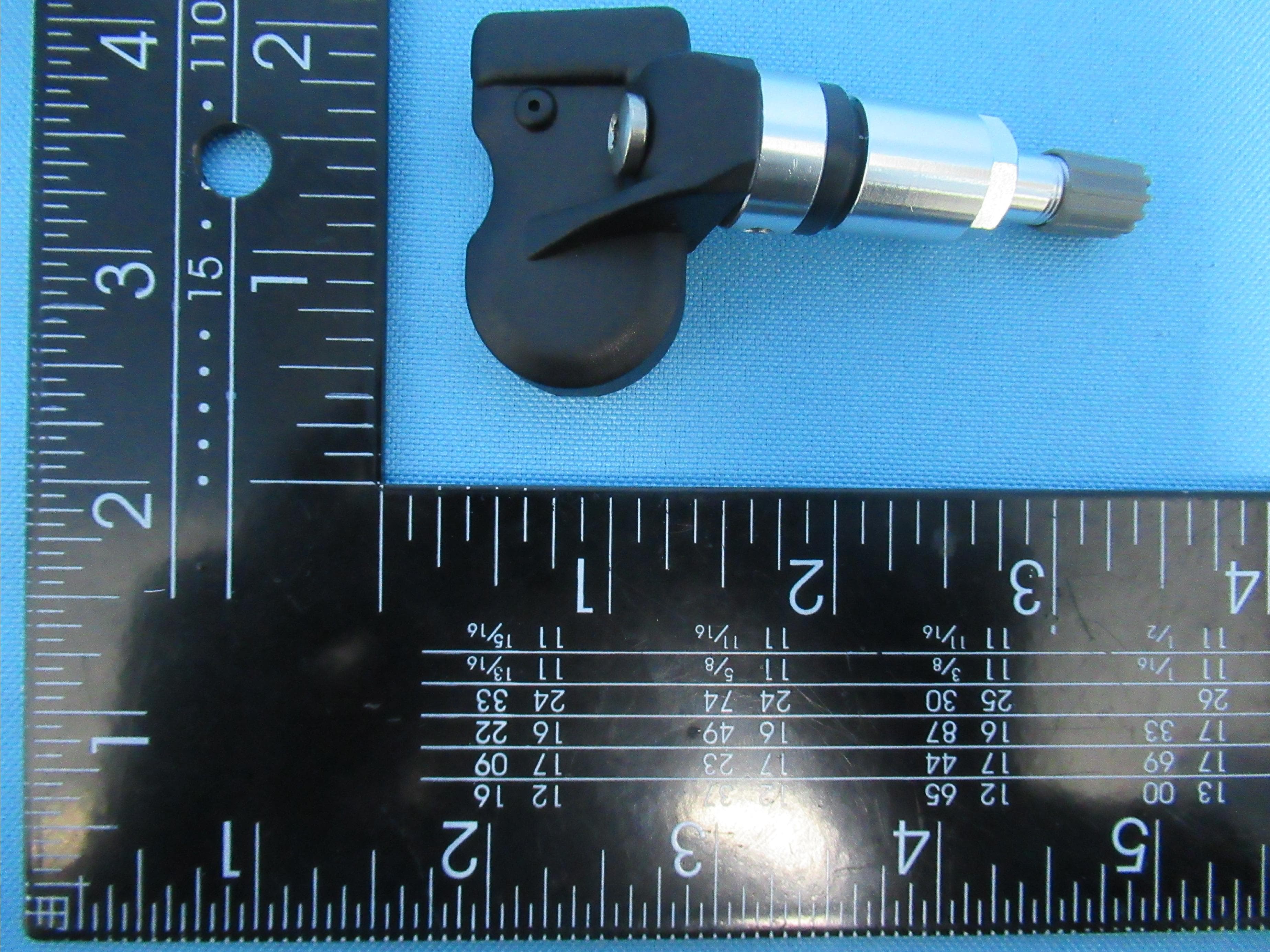
TTETSB60
Apr 14, 2021Tire Pressure Monitoring System Sensor
Equipment Class
DSC - Part 15 Security/Remote Control Transmitter
TTE-TSB44
Jul 15, 2015Tire Pressure Monitoring System
Equipment Class
DSC - Part 15 Security/Remote Control Transmitter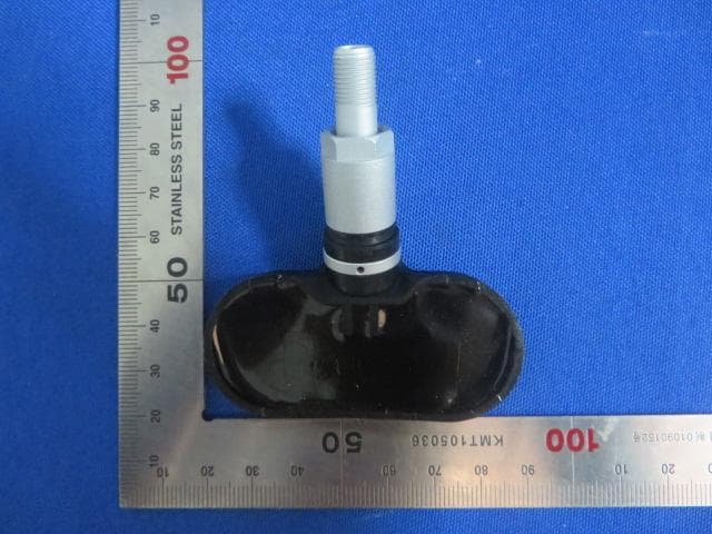
TTE-TSB41
Jul 12, 2015Tire Pressure Monitoring System
Equipment Class
DSC - Part 15 Security/Remote Control Transmitter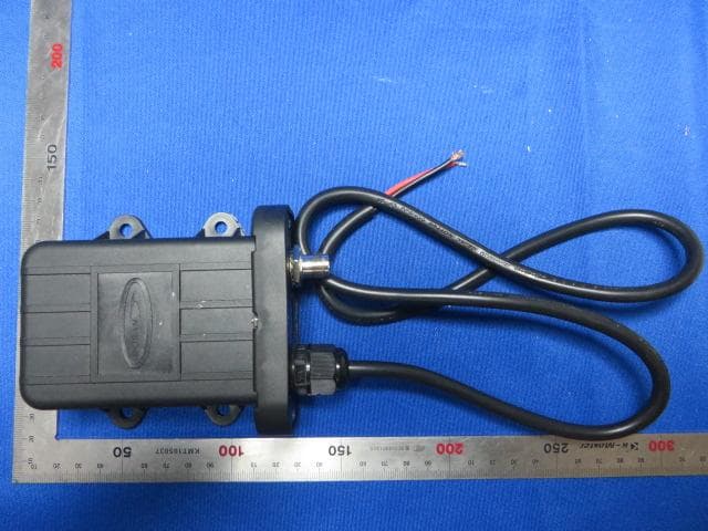
TTE3625
May 05, 2014Booster
Equipment Class
DSR - Part 15 Remote Control/Security Device Transceiver