TTERTGTPMSRIRE PRESSURE MONITORING SYSTEM
Suzhou Sate Auto Electronic Co., Ltd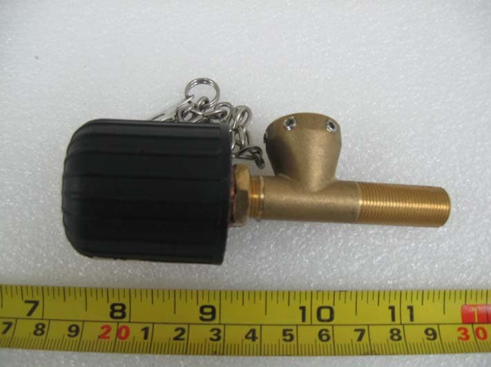
Click to zoom
Application Details
- Equipment Class
- DSC - Part 15 Security/Remote Control Transmitter
- Date of Grant
- Jan 28, 2008
- Application Purpose
- Original Equipment
- Date of Application
- Jan 27, 2008
- Equipment Note
- RIRE PRESSURE MONITORING SYSTEM
- Frequency Range
- 434.10000000 - 434.10000000
- Country
- China
Documents & Files
Document Text
Text extracted from the exhibit documents filed with the FCC. Open a document above to read the original.
Users Manual
RTG-TPMS INSTALL MANUAL Page 1 of 1 RTGTPMS8 INSTALL MANUAL RevisionV 1.04 Suzhou Sate Auto Electronic Co.Ltd RTG-TPMS INSTALL MANUAL Page 2 of 2 Content RTG-TPMS OVERVIEW 1. Instruction for Master Installation--------------------------------3 1) Master Overview------------------------------------------------3 2) Instruction for led indication----------------------------------5 3) Setting------------------------------------------------------------6 2. Instruction for Repeater Installation------------------------------8 3. Instruction for Sensors Installation-------------------------------9 4. Instruction for Maintenance--------------------------------------11 RTG-TPMS INSTALL MANUAL Page 3 of 3 RTG-TPMS-8 OVERVIEW RTG-TPMS-8 is the tire pressure monitoring system for the gantry crane, it monitors the pressure of tire full-time and alerters the driver with sound and light, at the same time the system can mutually interchange information with PLC, PC via communication socket. The system is made up of sensors, repeater and master. It can offer monitoring for 8 tires at most. Figure 1 Master Figure 2 Repeater Figure 3 Sensor 1. Master Install Manual 1.1 Master overview Figure 4 Master RTG-TPMS INSTALL MANUAL Page 4 of 4 2 Accessories of Master 1Power Wire 3-metre long power wire 2Communication Wire Figure 4 Communication Wire 3 Installation Step 1Fasten the Master on right position in the cab Figure 6 Screw Positions for Installing the Master 2 Adjust the angle of antenna to be vertical to master, screw the locknut on the antenna tightly. Locknut Screw Position M3X10 RTG-TPMS INSTALL MANUAL Page 5 of 5 3Connect the power wire Plug power plug into master power socket, and fasten power wire with tie. Note: Connect the red wire to anode 24V and black wire to cathode, screw the nut tightly. Figure 8 Power Wire Socket 4Connect the communication wire Plug DB9 connector into the Master socket, screw the nut tightly Figure 9 Communication Wire Socket Note: If no request, communication wire may not be installed. 5Error sign wire connection with PLC Connect one end (DB9 pin) of the error sign wire to the DB9 socket and fasten the screw. another end to the PLC I/O contact. Note: Connect the red wire to contact end of the PLC I/O module, black wire to the PLC GND. Caution Power Polar 4Introduction of LED indication When the pressure information transmitted by Sensors inside 1-8 tires are received, LED corresponding with tires on the Master will offer the corresponding indication. LED indicates green when pressure is normal. When pressure of any tire is lower than the low threshold of pressure, LED corresponding with tire will indicate red, at the same time LED light will flash with buzzer beep. When buzzer alarm, press any key on Master to stop beep, red LED will return into green until pressure of tire recover normality and Master receive data of normal pressure. When one of the sensors fails to work or Master could not receive the data for the interference from RF in the certain time, LED corresponding with the sensor will go out RTG-TPMS INSTALL MANUAL Page 6 of 6 automatically. LED light will return into green or red depended on pressure value until information of the sensor can be received. 5Setting Guide 1Sensor ID Setting 1) Press ID key and hold it for 3 seconds long, then release the key, as shown below. Digital “1” began to flash, at this time you can adjust it to the tire number you want by key ,such as , and then press ENTR . If you want to exit the setting of ID modified, adjust to” E” and then press ENTR to exit. 2) Then come into the interface of the tire unique ID you have chosen, the first digit on the right will flash, adjust the digit by and adjust the position of digit by After adjustment, press ENTR to save the specified unique ID, then automatically come into next tire number, repeat step 1 to set other ID. 2Low Threshold Pressure Setting Press P Key and hold it for 3 seconds long, then release it, picture will be shown like as below, the first digit on the right will flash, adjust the digit flashing by and adjust the position of digit by After adjustment, press ENTR to save current setting. Note: 1. Unit of pressure is indicated to be P or b, representing Psi or bar. 2. Value set is relative pressure value. 3. It is suggested that pressure value of tire on crane is set to be 9.50bar. RTG-TPMS INSTALL MANUAL Page 7 of 7 3Setting Pressure Unit Press ENTR key and hold it 3 seconds long, then release it. picture like down will be shown, digit 1 will flash, at this time adjust the digit to 2 by , then press ENTR At this time enter the step as below. You can press key to choose one from two alternation pressure unite in Psi (abbr. P) and bar (abbr. b)then press ENTR to exit 4Setting PLC type Press ENTR key for more than 3 seconds, picture like down will be shown, digit 1 will flash, at this time adjust the code of function you require by ,then press ENTR Then come into the picture shown down, select the code of PLC required by ,then press ENTR Index Index Type of PLC PLC Model 1 0 PC 2 1 Anchun PLC- CP370 3 2 Fiji PLCnot support currently RTG-TPMS INSTALL MANUAL Page 8 of 8 5Display Pressure Value in turn Pressure value of all tires will be displayed in turn when no action of pressing key on Master. The first digit on the left indicates current tire number (1-8). The second digit indicates current unit of pressure, “P” stands for “psi”, “b” for “bar”. The back four digits indicate current pressure. RTG-TPMS INSTALL MANUAL Page 9 of 9 2. Repeater Installation Manual 1. Assemble position sketch map The four repeaters should be installed on the I-section Beam of the equipment. They are on upper and lower side of the RTG separately. 2. Installation Step: Prepare Tool: screwer, M13 aid-spanner, M10 spanner, 3M insulating tape, fastening tie. 1. Fixing repeater at bottom board of the I-section beam, place proof-water connector adown. Fill up rubber gasket and fasten screws. 2. Connect the pow…
Text truncated - open the document above for the full version.
External Photos
SUZHOU SATE AUTO ELECTRONIC CO., LTD. MODEL: RTG-TPMS REPORT NO.: STR07128043I FCC PART 15.231 EXHIBIT 2 - EUT EXTERNAL PHOTOGRAPHS EUT View
ID Label/Location Info
SUZHOU SATE AUTO ELECTRONIC CO., LTD. MODEL: RTG-TPMS REPORT NO.: STR07128043I FCC PART 15.231 EXHIBIT 1- PRODUCT LABELING Proposed FCC ID Label Format FCC ID: TTERTGTPMS Specifications : Text is Black in color and justified. Labels are printed in indelible ink on permanent adhesive silk-screened onto the EUT or shall be affixed at a conspicuous location on the EUT. Proposed Label Location on EUT FCC ID Label Location
ID Label/Location Info
SUZHOU SATE AUTO ELECTRONIC CO., LTD. MODEL: RTG-TPMS REPORT NO.: STR07128043I FCC PART 15.231 EXHIBIT 1- PRODUCT LABELING Proposed FCC ID Label Format FCC ID: TTERTGTPMS Specifications : Text is Black in color and justified. Labels are printed in indelible ink on permanent adhesive silk-screened onto the EUT or shall be affixed at a conspicuous location on the EUT. Proposed Label Location on EUT FCC ID Label Location
Internal Photos
SUZHOU SATE AUTO ELECTRONIC CO., LTD. MODEL: RTG-TPMS REPORT NO.: STR07128043I FCC PART 15.231 EXHIBIT 3 - EUT INTERNAL PHOTOGRAPHS EUT Housing and Board View 1 EUT Housing and Board View 2 SUZHOU SATE AUTO ELECTRONIC CO., LTD. MODEL: RTG-TPMS REPORT NO.: STR07128043I FCC PART 15.231 Solder Board-Component View 1 Solder Board-Component View 2 SUZHOU SATE AUTO ELECTRONIC CO., LTD. MODEL: RTG-TPMS REPORT NO.: STR07128043I FCC PART 15.231 Solder Board-Component View 3 Solder Board-Component View 4
Test Report
SUZHOU SATE AUTO ELECTRONIC CO., LTD. MODEL: RTG-TPMS REPORT NO.: STR07128043I PAGE 1 OF 15 FCC PART 15.231 FCC PART 15.231 MEASUREMENT AND TEST REPORT FOR Suzhou Sate Auto Electronic Co., Ltd. 6F-138, Qingyun Road, Zhangjiang Hi-Tech Zone, Pudong New Area, Shanghai, 201203, P. R. China FCC ID: TTERTGTPMS Report Concerns: Original Report Equipment Type: Tire Pressure Monitoring System Model: RTG-TPMS Report No.: STR07128043I Test/Witness Engineer: Lahm Peng Test Date: 2007-12-20 to 2008-01-21 Prepared By: Shenzhen SEM.Test Compliance Service Co., Ltd. 3/F, Jinbao Commerce Building, Xin'an Fanshen Road, Bao'an District, Shenzhen, P.R.C.(518101) Approved & Authorized By: Jandy So / PSQ Manager Note: This test report is limited to the above client company and the product model only. It may not be duplicated without prior permitted by SEM.Test Compliance Service Co., Ltd . SUZHOU SATE AUTO ELECTRONIC CO., LTD. MODEL: RTG-TPMS REPORT NO.: STR07128043I PAGE 2 OF 15 FCC PART 15.231 TABLE OF CONTENTS 1. GENERAL INFORMATION ...................................................................................................................................3 1.1 PRODUCT DESCRIPTION FOR EQUIPMENT UNDER TEST (EUT)...............................................................................3 1.2 TEST STANDARDS...................................................................................................................................................3 1.3 RELATED SUBMITTAL(S)/GRANT(S) .......................................................................................................................3 1.4 TEST METHODOLOGY.............................................................................................................................................4 1.5 TEST FACILITY.......................................................................................................................................................4 1.6 EUT EXERCISE SOFTWARE....................................................................................................................................4 1.7 ACCESSORIES EQUIPMENT LIST AND DETAILS.......................................................................................................4 1.8 EUT CABLE LIST AND DETAILS.............................................................................................................................4 2. SUMMARY OF TEST RESULTS ...........................................................................................................................5 3. §15.203 - ANTENNA REQUIREMENT..................................................................................................................6 3.1 STANDARD APPLICABLE.........................................................................................................................................6 3.2 TEST RESULT..........................................................................................................................................................6 4. §15.205, §15.209, §15.231 (E)- RADIATED EMISSION........................................................................................7 4.1 MEASUREMENT UNCERTAINTY..............................................................................................................................7 4.2 STANDARD APPLICABLE.........................................................................................................................................7 4.3 TEST EQUIPMENT LIST AND DETAILS.....................................................................................................................8 4.4 TEST PROCEDURE...................................................................................................................................................8 4.5 CORRECTED AMPLITUDE & MARGIN CALCULATION..............................................................................................8 4.6 ENVIRONMENTAL CONDITIONS..............................................................................................................................9 4.7 SUMMARY OF TEST RESULTS/PLOTS......................................................................................................................9 5. §15.231(C) 20DB BANDWIDTH TESTING .........................................................................................................11 5.1 STANDARD APPLICABLE.......................................................................................................................................11 5.2 TEST EQUIPMENT LIST AND DETAILS...................................................................................................................11 5.3 TEST PROCEDURE.................................................................................................................................................11 5.4 ENVIRONMENTAL CONDITIONS............................................................................................................................11 5.5 SUMMARY OF TEST RESULTS/PLOTS....................................................................................................................11 6. §15.231(E)-DEACTIVATION TESTING..............................................................................................................13 6.1 STANDARD APPLICABLE.......................................................................................................................................13 6.2 TEST EQUIPMENT LIST AND DETAILS...................................................................................................................13 6.3 TEST PROCEDURE.................................................................................................................................................13 6.4 ENVIRONMENTAL CONDITIONS............................................................................................................................13 6.5 SUMM…
Text truncated - open the document above for the full version.
Test Setup Photos
SUZHOU SATE AUTO ELECTRONIC CO., LTD. MODEL: RTG-TPMS REPORT NO.: STR07128043I FCC PART 15.231 EXHIBIT 4 - TEST SETUP PHOTOGRAPHS Radiation Emission Test Setup (30MHz to 1GHz) Radiation Emission Test Setup (Above 1GHz)
Contact Information
Applicant
Justin Jia(G. M. of R & D)
Test Firm
Solid Industrial Co., Ltd.Yang Dengfang
Technical Specifications
| # | Rule Parts | Frequency Range | Power Output |
|---|---|---|---|
| 1 | 15.231 | 434.1 MHz - 434.1 MHz | - |
Other Applications from Suzhou Sate Auto Electronic Co., Ltd
TTE403112ZG1A
Jul 20, 2026Tire pressure sensor
Equipment Class
DSC - Part 15 Security/Remote Control Transmitter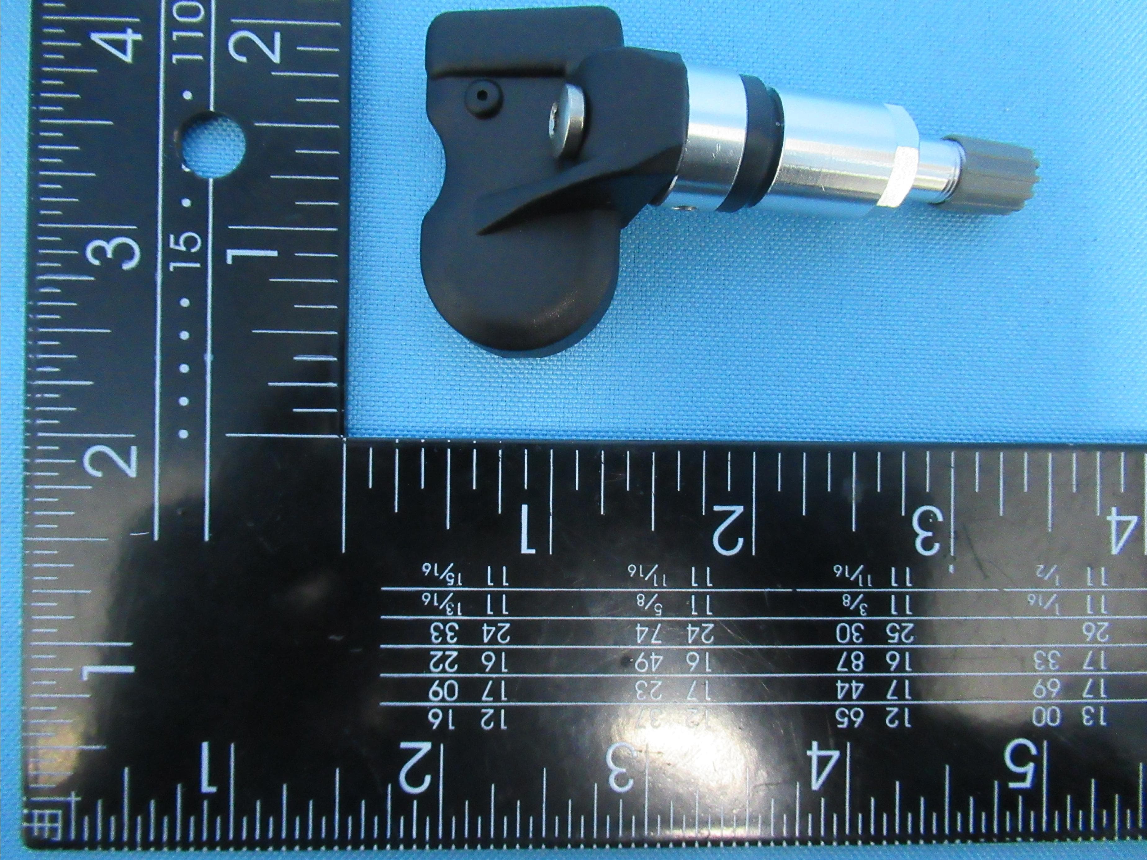
TTETSB60
Apr 14, 2021Tire Pressure Monitoring System Sensor
Equipment Class
DSC - Part 15 Security/Remote Control Transmitter
TTE-TSB44
Jul 15, 2015Tire Pressure Monitoring System
Equipment Class
DSC - Part 15 Security/Remote Control Transmitter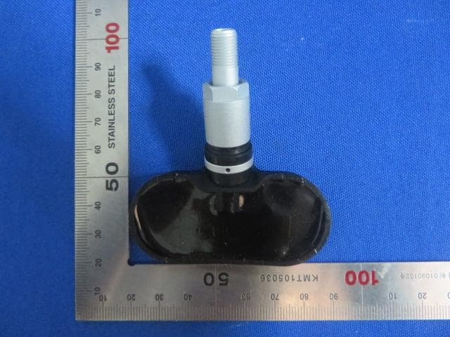
TTE-TSB41
Jul 12, 2015Tire Pressure Monitoring System
Equipment Class
DSC - Part 15 Security/Remote Control Transmitter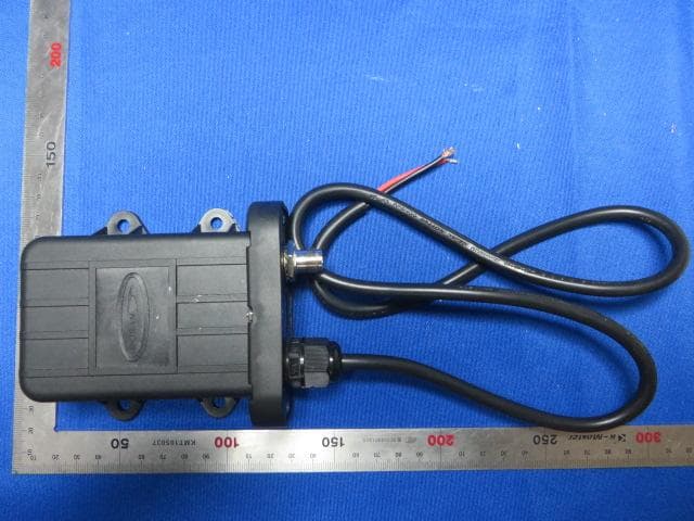
TTE3625
May 05, 2014Booster
Equipment Class
DSR - Part 15 Remote Control/Security Device Transceiver