TTETPMS09S22TIRE PRESSURE MONITORING SYSTEM
Suzhou Sate Auto Electronic Co., Ltd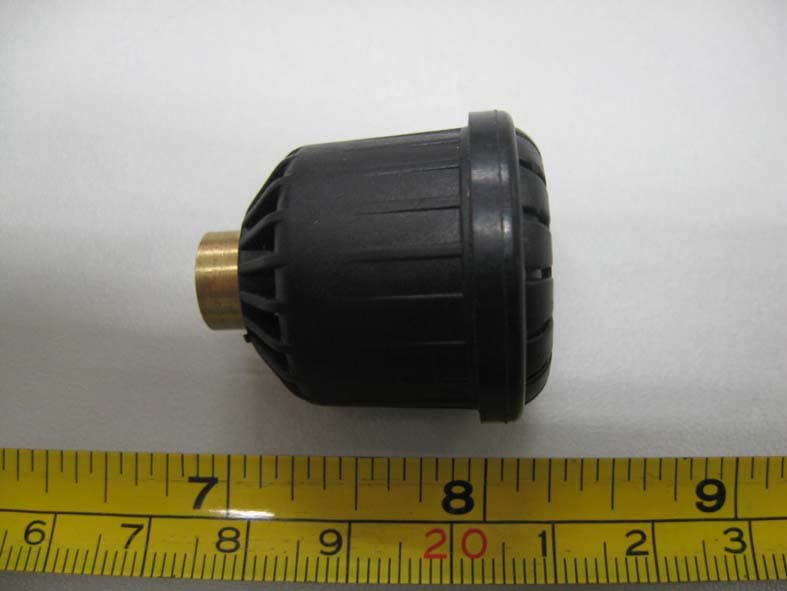
Click to zoom
Application Details
- Equipment Class
- DSC - Part 15 Security/Remote Control Transmitter
- Date of Grant
- Feb 04, 2008
- Application Purpose
- Original Equipment
- Date of Application
- Feb 03, 2008
- Equipment Note
- TIRE PRESSURE MONITORING SYSTEM
- Frequency Range
- 434.10000000 - 434.10000000
- Country
- China
Documents & Files
Document Text
Text extracted from the exhibit documents filed with the FCC. Open a document above to read the original.
Users Manual
User Manual FCC ID: TTETPMS09S22 TPMS1209TS22 is a full-time direct tire pressure monitoring system which includes one wireless Monitor. User can choose 2 to 36 Transmitters to install on their vehicles as needed. The Transmitter can be screwed onto the tire instead of the cap of the valve and then senses the pressure inside the tire all the time and transmits the pressure information data to the Booster by RF technology. The Booster then signifies the signal and transmits it to the Monitor. The Monitor can receive and deal with the data, then display the pressure on the screen. The Monitor can issue different alarms if the tire pressure is at an improper level based on the standard pressure. TPMS1209TS22 can sense and display the tire pressure all the time and can issue an alarm when the tire pressure is improper, so as to notify the driver to treat the problem and avoid tire busting or tire damage. Through TPMS, the driver can keep the tire running under a proper pressure so as to avoid excess gasoline consumption and keep the vehicle in an easily controlled state. Transmitter and the Security Lock Installation of the Transmitter Before installing the Transmitter, the Monitor must be powered on and then it will be under the “waiting” mode (waiting for receiving the ID information). At this time, if the Transmitter is installed, its ID information will be received and recorded by the Monitor. However, the Monitor can only record one Transmitter’s ID information each time. So before another Transmitter is installed, the ID information of the previous installed Transmitter must be received and recorded by the Monitor. The Installation steps of the Transmitter are as follows: 1. Inflate the tire to the standard pressure recommended by the manufacturer. 2. Take out a Transmitter and check whether the rubber seal is placed smoothly and suitably inside the copper stem of the valve. 3. Screw off the current cap of the valve on the tire. Note: IMPORTANT. TPMS1209TS22 provides a Lock for each Transmitter to prevent the Transmitter from falling off. Whether use the Lock or not won’t influence the work of the Transmitter. If you want to install the Security Lock, Please follow the Installation steps of the Transmitter Lock below. The Lock must be installed onto the valve before the installation of the Transmitter. 4. Screw the Transmitter onto the valve of the tire. 5. Check the connection of Transmitter and valve with the soap solution to confirm whether the Transmitter is firmly screwed onto the valve or not, check whether there is air leakage caused by the installation or the seal of the Transmitters or not. 6. Once screwed onto the tire, Transmitter can sense the pressure inside the tire and transmit the data to the Monitor, and the information will appear on the screen within 6 minutes. Note 1. Before installing the Transmitter, please program the standard pressure on the Monitor. The default standard pressure is set to 100psi in factory. 2. If one of the Transmitters is broken or fails to work, the others can still function well. Only the broken one or the lost one needs to be changed. TPMS1209TS22 has a Security Lock and a special tool for the lock for each Transmitter to prevent the Transmitter from loosing or falling off. The Security Lock has three sockets on it and each socket has a bolt in it, as shown in the above figure. The function of the lock is to connect the Transmitter and the Lock by connecting the meshing part of them, and then fasten the lock to the valve by the three bolts. Thus the Lock together with the Transmitter can be firmly fixed onto the valve and will not be easily removed or be screwed off by a sudden force while running. The customer can choose to use the locker or not. Installing the lock or not will not influence the functions of the Transmitter. Note: If the customer chooses to use the Lock, the following installing steps should be inserted follow the Transmitter Installing Term 4. Installation step of the Security Lock 1. Connect the meshing part of the Transmitter and the Lock First connect the meshing parts of the Lock and the Transmitter to make them to be integrated, then screw the Transmitter together with the Locker firmly onto the valve, as shown in the figure on the left. 2. Lock the Transmitter Use the special tool to screw the three bolts inside the sockets on the lock, let the Lock together with the Transmitter screw firmly onto the valve, as shown in the figure on the left. Then the Transmitter can not be screwed off unless you screw off the Lock with the special tool. How to inflate the tire with a locked Transmitter BEFORE inflating the tire, please 1) Use the special tool to loose the three bolts inside the sockets on the Lock. 2) Screw off the Transmitter. 3) Remove the Transmitter together with the Security Lock from the Valve Note: 1.The Security Lock will not influence the Transmitter’s work, you can choose using the Lock or not while you install the Transmitter. 2. The tires need to be re-balanced after installing the Transmitter or the Transmitter with the Lock. FCC Caution This device complies with Part 15 of the FCC Rules. Operation is subject to the following two conditions: (1) this device may not cause harmful interference, and (2) this device must accept any interference received, including interference that may cause undesired operation. FCC Notes: The manufacturer is not responsible for and radio or TV interference caused by unauthorized modifications to this equipment. Such modifications could void the user's authority to operate the equipment.
External Photos
SUZHOU SATE AUTO ELECTRONIC CO., LTD. MODEL: TPMS1209TS22 Report No.: STR07128046I FCC PART 15.231 EXHIBIT 2 - EUT EXTERNAL PHOTOGRAPHS EUT View 1
ID Label/Location Info
SUZHOU SATE AUTO ELECTRONIC CO., LTD. MODEL: TPMS1209TS22 Report No.: STR07128046I FCC PART 15.231 EXHIBIT 1- PRODUCT LABELING Proposed FCC ID Label Format FCC ID: TTETPMS09S22 Specifications : Labels are printed in indelible ink on permanent adhesive silk-screened onto the EUT or shall be affixed at a conspicuous location on the EUT. Proposed Label Location on EUT FCC ID Label Location
ID Label/Location Info
SUZHOU SATE AUTO ELECTRONIC CO., LTD. MODEL: TPMS1209TS22 Report No.: STR07128046I FCC PART 15.231 EXHIBIT 1- PRODUCT LABELING Proposed FCC ID Label Format FCC ID: TTETPMS09S22 Specifications : Labels are printed in indelible ink on permanent adhesive silk-screened onto the EUT or shall be affixed at a conspicuous location on the EUT. Proposed Label Location on EUT FCC ID Label Location
Internal Photos
SUZHOU SATE AUTO ELECTRONIC CO., LTD. MODEL: TPMS1209TS22 Report No.: STR07128046I FCC PART 15.231 EXHIBIT 3 - EUT INTERNAL PHOTOGRAPHS EUT Housing and Board View 1 EUT Housing and Board View 2 SUZHOU SATE AUTO ELECTRONIC CO., LTD. MODEL: TPMS1209TS22 Report No.: STR07128046I FCC PART 15.231 Solder Board-Component View 1 Solder Board-Component View 2 SUZHOU SATE AUTO ELECTRONIC CO., LTD. MODEL: TPMS1209TS22 Report No.: STR07128046I FCC PART 15.231 Solder Board-Component View 3 Solder Board-Component View 4 SUZHOU SATE AUTO ELECTRONIC CO., LTD. MODEL: TPMS1209TS22 Report No.: STR07128046I FCC PART 15.231 Solder Board-Component View 5
Test Report
SUZHOU SATE AUTO ELECTRONIC CO., LTD. MODEL: TPMS1209TS22 REPORT NO.: STR07128046I PAGE 1 OF 15 FCC PART 15.231 FCC PART 15.231 MEASUREMENT AND TEST REPORT FOR Suzhou Sate Auto Electronic Co., Ltd. 6F-138, Qingyun Road, Zhangjiang Hi-Tech Zone, Pudong New Area, Shanghai, 201203, P. R. China FCC ID: TTETPMS09S22 Report Concerns: Original Report Equipment Type: Tire Pressure Monitoring System Model: TPMS1209TS22 Report No.: STR07128046I Test/Witness Engineer: Test Date: 2008-01-18 to 2008-01-21 Prepared By: Shenzhen SEM.Test Compliance Service Co., Ltd 3/F, Jinbao Commerce Building, Xin'an Fanshen Road, Bao'an District, Shenzhen, P.R.C. (518101) Approved & Authorized By: Jandy So / PSQ Manager Note: This test report is limited to the above client company and the product model only. It may not be duplicated without prior permitted by SEM.Test Compliance Service Co., Ltd . SUZHOU SATE AUTO ELECTRONIC CO., LTD. MODEL: TPMS1209TS22 REPORT NO.: STR07128046I PAGE 2 OF 15 FCC PART 15.231 TABLE OF CONTENTS 1. GENERAL INFORMATION ...................................................................................................................................3 1.1 PRODUCT DESCRIPTION FOR EQUIPMENT UNDER TEST (EUT)...............................................................................3 1.2 TEST STANDARDS...................................................................................................................................................3 1.3 RELATED SUBMITTAL(S)/GRANT(S) .......................................................................................................................4 1.4 TEST METHODOLOGY.............................................................................................................................................4 1.5 TEST FACILITY.......................................................................................................................................................4 1.6 EUT EXERCISE SOFTWARE....................................................................................................................................4 1.7 ACCESSORIES EQUIPMENT LIST AND DETAILS.......................................................................................................4 1.8 EUT CABLE LIST AND DETAILS.............................................................................................................................4 2. SUMMARY OF TEST RESULTS ...........................................................................................................................5 3. §15.203 - ANTENNA REQUIREMENT..................................................................................................................6 3.1 STANDARD APPLICABLE.........................................................................................................................................6 3.2 TEST RESULT..........................................................................................................................................................6 4. §15.205, §15.209, §15.231 (B)- RADIATED EMISSION........................................................................................7 4.1 MEASUREMENT UNCERTAINTY..............................................................................................................................7 4.2 STANDARD APPLICABLE.........................................................................................................................................7 4.3 TEST EQUIPMENT LIST AND DETAILS.....................................................................................................................8 4.4 TEST PROCEDURE...................................................................................................................................................8 4.5 CORRECTED AMPLITUDE & MARGIN CALCULATION..............................................................................................9 4.6 ENVIRONMENTAL CONDITIONS..............................................................................................................................9 4.7 SUMMARY OF TEST RESULTS/PLOTS......................................................................................................................9 5. §15.231(C) 20DB BANDWIDTH TESTING .........................................................................................................11 5.1 STANDARD APPLICABLE.......................................................................................................................................11 5.2 TEST EQUIPMENT LIST AND DETAILS...................................................................................................................11 5.3 TEST PROCEDURE.................................................................................................................................................11 5.4 ENVIRONMENTAL CONDITIONS............................................................................................................................11 5.5 SUMMARY OF TEST RESULTS/PLOTS....................................................................................................................11 6. §15.231(A)-DEACTIVATION TESTING .............................................................................................................13 6.1 STANDARD APPLICABLE.......................................................................................................................................13 6.2 TEST EQUIPMENT LIST AND DETAILS...................................................................................................................13 6.3 TEST PROCEDURE.................................................................................................................................................13 6.4 ENVIRONMENTAL CONDITIONS............................................................................................................................13 6.5 …
Text truncated - open the document above for the full version.
Contact Information
Applicant
Justin Jia(G. M. of R & D)
Test Firm
Solid Industrial Co., Ltd.Yang Dengfang
Technical Specifications
| # | Rule Parts | Frequency Range | Power Output |
|---|---|---|---|
| 1 | 15.231(e) | 434.1 MHz - 434.1 MHz | - |
Other Applications from Suzhou Sate Auto Electronic Co., Ltd
TTE403112ZG1A
Jul 20, 2026Tire pressure sensor
Equipment Class
DSC - Part 15 Security/Remote Control Transmitter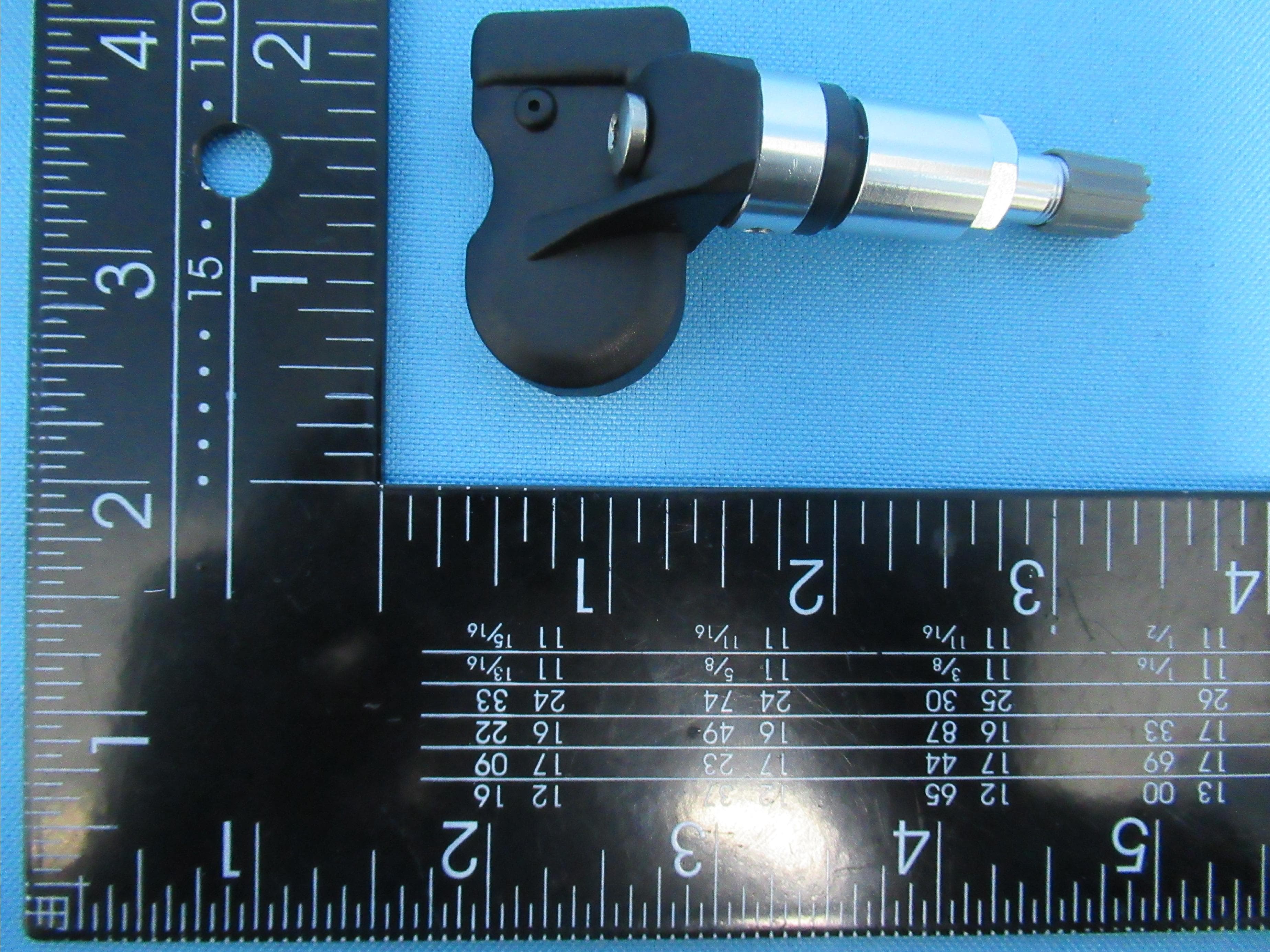
TTETSB60
Apr 14, 2021Tire Pressure Monitoring System Sensor
Equipment Class
DSC - Part 15 Security/Remote Control Transmitter
TTE-TSB44
Jul 15, 2015Tire Pressure Monitoring System
Equipment Class
DSC - Part 15 Security/Remote Control Transmitter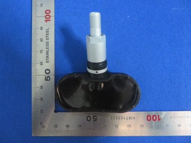
TTE-TSB41
Jul 12, 2015Tire Pressure Monitoring System
Equipment Class
DSC - Part 15 Security/Remote Control Transmitter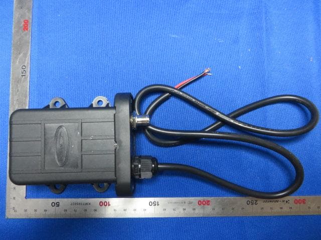
TTE3625
May 05, 2014Booster
Equipment Class
DSR - Part 15 Remote Control/Security Device Transceiver