TTM-102P40IDigital Microwave Radio
Exalt Wireless, Inc.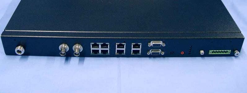
Click to zoom
Application Details
- Equipment Class
- DTS - Digital Transmission System
- Date of Grant
- Apr 06, 2006
- Application Purpose
- Original Equipment
- Date of Application
- Apr 06, 2006
- Equipment Note
- Digital Microwave Radio
- Frequency Range
- 2406.00000000 - 2468.00000000
- Company
- Exalt Wireless, Inc.
- Country
- United States
Documents & Files
Document Text
Text extracted from the exhibit documents filed with the FCC. Open a document above to read the original.
Users Manual
EX-2.4i 2.4GHz Digital Microwave Radio Installation and Maintenance Manual Document: MAN-002400 Revision: 001 Date: 2005-12-01 E E X A X A L T L T E E C o m m u n i c a t i o n s E E X A X A L T L T E E C o m m u n i c a t i o n s E E X A X A L T L T E E E E X A X A L T L T E E C o m m u n i c a t i o n s Exalt Communications Inc. EX-2.4i Installation and Maintenance Manual Page i MAN-002400, Revision 001 2005-12-01 Legal Notice The information contained herein is the property of Exalt Communications Inc. (Exalt) and is supplied without liability for errors or omissions. No part of this document may be reproduced, in any form, except as authorized by contract or other written permission from the owner. Any brand names and product names included in this manual are trademarks, registered trademarks, or trade names of their respective holders. The contents of this document are current as of the date of publication. Exalt reserves the right to change the contents without prior notice. In no event will Exalt be liable for any special, incidental, or consequential damages or for commercial losses in connection with the furnishing, performance, or use of this manual or equipment supplied with this manual, including, but not limited to, the implied warranties of merchantability and fitness for a particular purpose. The publication of information in this document does not imply freedom from patent or other rights of Exalt or others. © Exalt Communications Inc., December, 2005. All rights reserved. Y2K Statement: All imbedded or external software/firmware supplied by Exalt adhere to the four-digit year nomenclature as required for Year 2000 compliance. Exalt Communications Inc. EX-2.4i Installation and Maintenance Manual Page ii MAN-002400, Revision 001 2005-12-01 About this Document This manual provides a complete description of the Exalt EX-2.4i Digital Microwave Radio and related software. The purpose of this manual is to provide the planner, engineer, installer, system administrator, and technician with general and specific information related to the planning, installation, operation, management and maintenance of the device. Revision History Revision Date Detail 001 2005-12-01 Initial release. Icons Throughout this document, the following icons are used to denote specific types of information as described here. (Warning) Denotes information pertaining to potential danger to human life. (Caution) Denotes information pertaining to potential danger to property. (Note) Denotes information that may be particularly useful or unique ! CAUTION Exalt Communications Inc. EX-2.4i Installation and Maintenance Manual Page iii MAN-002400, Revision 001 2005-12-01 General Compliance and Safety The usage of radio transmission devices is subject to specific regulatory requirements governed by regional legislation. In most cases, the specific device must be authorized for use in a given country and must be installed and adjusted in accordance with specific radio-frequency settings and in a manner that has been authorized specific to the device itself in accordance with the specific location of the device. Some users may be completely or partially restricted from use of the device. Please consult your governmental agency/agencies for regulatory requirements before use, or contact Exalt or your dealer for assistance. This device may not be modified in any way without the express written consent of Exalt. Modification will not only void the manufacturer warranty, but may also be expressly illegal in accordance to government regulations. In addition, there are no user-serviceable parts or assemblies inside the product housing. There may also be voltages, signals and mechanisms within the device that could be harmful to human safety. The mounting of this device and associated peripherals and connections (inclusive of antenna mast, antenna, cabling, egress, lightning protection devices, grounding, power, etc.) may be subject to regional requirements for health and human safety. A qualified professional installer and an electrician are highly recommended, and may be required by law. For example, within the USA, this device must be professionally installed. Exalt cannot warrant the device or be found liable for any unauthorized use or installation of the device. Regulatory Notices Federal Communications Commission (FCC), United States The device is allowed to be used provided it does not cause interference to other devices. It is not guaranteed to provide protection against interference from other electronic and radio devices. The system has been tested and found to comply with the limits a class B digital device, pursuant to Part 15 of the FCC Rules. These limits are designed to provide reasonable protection against harmful interference in a residential installation. This equipment generates, uses and can radiate radio frequency energy and, if not installed and used in accordance with the instructions, may cause harmful interference to radio communications. However, there is no guarantee that interference will not occur in a particular installation. If this equipment does cause harmful interference to radio or television reception, which can be determined by turning the equipment off and on, the user is encouraged to try to correct the interference by one of more of the following measures: Exalt Communications Inc. EX-2.4i Installation and Maintenance Manual Page iv MAN-002400, Revision 001 2005-12-01 • Reorient or relocate the receiving antenna. • Increase the separation between the equipment and receiver. • Connect the equipment into an outlet on a circuit different from that to which the receiver is connected. • Consult the dealer or an experienced radio/TV technician for help. Shielded cables and I/O cords must be used for this equipment to comply with the relevant FCC regulations. Changes or modifications not expressly approved in writing by Exalt may void the user’s authority to operate this equipment. This devi…
Text truncated - open the document above for the full version.
Users Manual
Exalt Communications Inc. 580 Division St. Campbell, CA 95008 USA telephone: +1 (408) 871-1804 fax: +1 (408) 871-9750 December 8, 2005 Federal Communications Commission 7435 Oakland Mills Road Columbia, MD 21046 RE: Professional Installation Requirement for Exalt Communications Inc. EX-2.4i (FCC ID: TTM-1Ø2P4ØI) Dear Sirs/Madam, This document is provided to describe the need for the EX-2.4i to be professionally installed, and, as such, is exempt from the antenna restrictions of FCC Part 15.203. Use The EX-2.4i is a fixed permanent or temporary outdoor point-to-point microwave radio used for joining industrial and commercial locations to connect voice (TDM) and/or data (Ethernet) circuits. The EX-2.4i is mounted in a telecommunications rack or environmental cabinet, and the associated antennas are mounted on towers or specifically-constructed antenna masts on buildings or other structures. Installation The engineering and installation of fixed microwave systems requires specific expertise in microwave transmission planning and engineering, antenna installation, antenna alignment, grounding, lightning protection, transmission line installation and site construction. Furthermore, the connection of TDM circuits requires specific expertise in the area of telecommunications configuration. The Installation and Maintenance Manual specifically states that the products must be professionally installed, and provides the details for proper output power setting in accordance to the antenna and transmission system deployed. Output power setting may only be accessed by the system administrator, and not by the user. Marketing Exalt sells the EX-2.4i through an exclusive group of telecommunications distributors who are chosen by and under contract to Exalt Communications. These distributors sell to Value Added Resellers and Telecommunications companies that are specifically qualified in the area of fixed microwave engineering and installation, and Exalt monitors the sale of every system. These systems are not marketed and sold to the general public, not sold in retail outlets or by mail order. Customers will purchase the antennas and transmission system from these same distributors. A list of acceptable antennas is listed in the Installation and Maintenance Manual. If you have any questions, please do not hesitate to contact me. Sincerely, Ken Ruppel Director, Customer Engineering Exalt Communications Inc. [email protected] 408-871-1804 x226
External Photos
the wireless lab February 6, 2006 EXLT01 – A1 – 2.4 GHz Point to Point Fixed Link Radio Exalt Communications, Inc. External Photographs Model 2400 MiCOM Labs, 3922 Valley Avenue, Suite “B”, Pleasanton, CA 94566 Tel: +1 (925) 462-0304, Fax: +1 (925) 462-0306, Web: www.micomlabs.com
ID Label/Location Info
17.0” 13.6” LABEL Model: EX-2.4i FCC ID: TTM-1Ø2P4ØI CANADA: 6254A-1Ø2P4ØI Electrical Ratings: +48VDC, 0.7 A The device complies with Part 15 of the FCC Rules and IC: RSS-210. Operation is subject to the following conditions: (1) This device may not cause harmful interference. (2) This device must accept any interference received, including interference that may cause undesired operation. (3) This device must be professionally installed. MADE IN USA Part Number — Serial Number E123456 — 1234567890 P/N S/N MAC Address 12:34:56:78:90:AB MAC 1.65” 3.3” Regulatory Label Detail, and Label Location Exalt Communications Inc EX-2.4i Rear Panel View – Label Location
Operational Description
3922 Valley Avenue, Suite “B”, Pleasanton, California 94566 USA Tel: 1 925 462 0304, Fax: 1 925 462 306 www.micomlabs.com Wednesday, 1 st March 2006 EXLT01-A1 Exalt Communications Inc , Model 2400 Antenna Gains, Transmit Power Settings, and Minimum Safe Distance FCC, Part 15 Subpart C §15.247(b) Calculations for Maximum Permissible Exposure Levels Power Density = Pd (mW/cm 2 ) = EIRP/(4πd 2 ) EIRP = P * G P = Peak output power (mW) G = Antenna numeric gain (numeric) d = Separation distance (cm) Numeric Gain = 10 ^ (G (dBi)/10) P (worst case) = +29.96 dBm, 990.80 mW Antenna Gain (Worst Case) = 30.3 dBi, 1071.5 numeric Because the EUT belongs to the General Population/Uncontrolled Exposure the limit of power density is 1.0 mW/cm 2 Antenna Gain - Maximum Allowable Power Level For fixed point to point operation. Systems operating in the 2400-2483.5 MHz band that are used exclusively for fixed, point-to-point operations may employ transmitting antennas with directional gain greater than 6 dBi provided the maximum conducted output power of the intentional radiator is reduced by 1 dB for every 3 dB that the directional gain of the antenna exceeds 6 dBi. Antenna Gain (dBi) Numeric Gain (numeric) Antenna Gain >6dBi (dB) Power Reduction (dB) Max Allowable Peak Power (dBm) Max Allowable Peak Power (mW) Calculated Safe Distance at 1 mW/cm 2 (cm) 21.3 134.9 15.3 5.10 24.9 309.03 57.60 30.3 1071.5 24.3 8.10 21.9 154.88 114.92 20.0 100 14.0 4.67 25.3 338.84 51.93
Test Report
Test of Exalt Communications Inc EX-2.4i To FCC 47 CFR Part 15.247 & IC RSS-210 Test Report Serial No.: EXLT01-A1 Rev B This test report may be reproduced in full only. The document may only be updated by MiCOM Labs personnel. Any changes will be noted in the Document History section of the report. MiCOM Labs is an ISO 17025 Accredited Testing Laboratory CERTIFICATE #2381.01 TEST REPORT FROM Test of Model EX-2.4i To FCC 47 CFR Part15.247 & IC RSS-210 Test Report Serial No.: EXLT01-A1 Rev B This report supersedes None Manufacturer: Exalt Communications, Inc 580 Division Street Campbell, California 95008 USA Product Function: 2.4 GHz Point to Point Fixed Link Radio Copy No: pdfIssue Date: 30th March 2006 UThis Test Report is Issued Under the Authority of;U MiCOM Labs, Inc. 3922 Valley Avenue, Suite B Pleasanton, CA 94566 USA Phone: +1 (925) 462-0304 Fax: +1 (925) 462-0306 HTUwww.micomlabs.comUTH Title: To: Serial #: Issue Date: Page: Model EX-2.4i FCC 47 CFR Part15.247 & IC RSS-210 EXLT01-A1 Rev B 30th March 2006 2 of 246 This test report may be reproduced in full only. The document may only be updated by MiCOM Labs personnel. Any changes will be noted in the Document History section of the report. MiCOM Labs, 3922 Valley Avenue, Suite B, Pleasanton, CA 94566 USA, Phone: 925.462.0304, Fax: 925.462.0306, www.micomlabs.com This page has been left intentionally blank Title: To: Serial #: Issue Date: Page: Model EX-2.4i FCC 47 CFR Part15.247 & IC RSS-210 EXLT01-A1 Rev B 30th March 2006 3 of 246 This test report may be reproduced in full only. The document may only be updated by MiCOM Labs personnel. Any changes will be noted in the Document History section of the report. MiCOM Labs, 3922 Valley Avenue, Suite B, Pleasanton, CA 94566 USA, Phone: 925.462.0304, Fax: 925.462.0306, www.micomlabs.com UTABLE OF CONTENTS ACCREDITATION & LISTINGS .......................................................................................... 4 1. TEST RESULT CERTIFICATE..................................................................................... 7 2. REFERENCES AND MEASUREMENT UNCERTAINTY........................................... 8 2.1. Normative References ............................................................................................... 8 2.2. Test and Uncertainty Procedures .............................................................................. 8 3. PRODUCT DETAILS AND TEST CONFIGURATIONS ............................................. 9 3.1. Technical Details ....................................................................................................... 9 3.2. Scope of Test Program ............................................................................................ 11 3.3. Equipment Model(s) and Serial Number(s) ............................................................. 12 3.4. Antenna Details ....................................................................................................... 13 3.5. Cabling and I/O Ports .............................................................................................. 13 3.6. Test Configurations.................................................................................................. 14 3.7. Equipment Modifications.......................................................................................... 14 3.8. Deviations from the Test Standard .......................................................................... 14 3.9. Subcontracted Testing or Third Party Data ............................................................. 15 4. TEST SUMMARY ........................................................................................................ 16 5. TEST RESULTS .......................................................................................................... 18 5.1. Device Characteristics ............................................................................................. 18 5.1.1. 6 dB and 99 % Bandwidth............................................................................ 18 5.1.2. Peak Output Power ...................................................................................... 44 5.1.3. Peak Power Spectral Density ...................................................................... 58 5.1.4. Maximum Permissible Exposure.................................................................. 72 5.1.5. Conducted Spurious Emissions ................................................................... 74 5.1.6. Radiated Emissions ................................................................................... 134 5.1.7. AC Wireline Conducted Emissions (150 kHz – 30 MHz) ........................... 239 6. PHOTOGRAPHS....................................................................................................... 242 6.1. Radiated Emissions (30 MHz-1 GHz) .................................................................... 242 6.2. Radiated Emissions >1 GHz.................................................................................. 243 6.3. Conducted Emissions (150 kHz - 30 MHz) ............................................................ 244 6.4. General Measurement Test Set-Up ....................................................................... 245 7. TEST EQUIPMENT DETAILS .................................................................................. 246 Title: To: Serial #: Issue Date: Page: Model EX-2.4i FCC 47 CFR Part15.247 & IC RSS-210 EXLT01-A1 Rev B 30th March 2006 4 of 246 This test report may be reproduced in full only. The document may only be updated by MiCOM Labs personnel. Any changes will be noted in the Document History section of the report. MiCOM Labs, 3922 Valley Avenue, Suite B, Pleasanton, CA 94566 USA, Phone: 925.462.0304, Fax: 925.462.0306, www.micomlabs.com ACCREDITATION & LISTINGS MiCOM Labs, Inc. an accredited laboratory complies with the international standard BS EN ISO/IEC 17025. The company is accredited by the American As…
Text truncated - open the document above for the full version.
Test Setup Photos
the wireless lab February 6, 2006 EXLT01 – A1 – 2.4 GHz Point to Point Fixed Link Radio Exalt Communications, Inc. TEST SET-UP PHOTOGRAPHS General Measurement Test Set-Up MiCOM Labs, 3922 Valley Avenue, Suite “B”, Pleasanton, CA 94566 Tel: +1 (925) 462-0304, Fax: +1 (925) 462-0306, Web: www.micomlabs.com the wireless lab Radiated Emissions (30 MHz-1 GHz) Page 2 of 4 the wireless lab Radiated Emissions >1 GHz Page 3 of 4 the wireless lab Conducted Emissions (150 kHz - 30 MHz) Page 4 of 4
Contact Information
Applicant
Tuyen Banh
Test Firm
MiCOM LabsGordon Hurst
Technical Specifications
| # | Rule Parts | Frequency Range | Power Output |
|---|---|---|---|
| 1 | 15C | 2.41 GHz - 2.47 GHz | 1 W |
Other Applications from Exalt Wireless, Inc.

TTM-105P25U
Jun 18, 2013eMIMO 100
Equipment Class
TNB - Licensed Non-Broadcast Station Transmitter
TTM-105P25T
Mar 13, 2013Radio Module 5GHz
Equipment Class
NII - Unlicensed National Information Infrastructure TX
TTM-105P25P
Oct 02, 2011Ex-i Series 5.8GHz Radio Module
Equipment Class
DTS - Digital Transmission System
TTM-124P05N
Sep 11, 201124GHz Radio
Equipment Class
DXX - Part 15 Low Power Communication Device Transmitter
TTM-104P94N
Feb 07, 20104.9 GHz Radio Module
Equipment Class
TNB - Licensed Non-Broadcast Station Transmitter