TTM-104P90M4.9GHz Point to Point Fixed Link Radio
Exalt Wireless, Inc.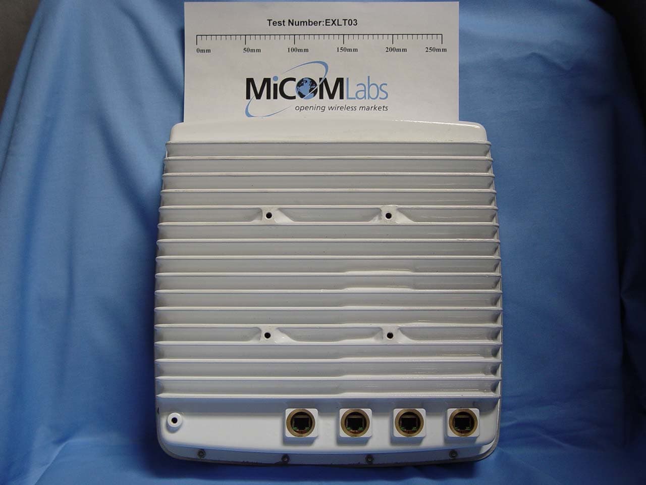
Click to zoom
Application Details
- Equipment Class
- TNB - Licensed Non-Broadcast Station Transmitter
- Date of Grant
- Aug 06, 2007
- Application Purpose
- Original Equipment
- Date of Application
- Aug 06, 2007
- Equipment Note
- 4.9GHz Point to Point Fixed Link Radio
- Frequency Range
- 4950.00000000 - 4980.00000000
- Company
- Exalt Wireless, Inc.
- Country
- United States
Documents & Files
Document Text
Text extracted from the exhibit documents filed with the FCC. Open a document above to read the original.
Users Manual
i-Series Digital Microwave Radios Installation and Management Guide Models included: EX-2.4i EX-2.4i-16 EX-4.9i EX-5i EX-5i-16 Part Number: 50000001 Date: 2007-01-03 (draft) Exalt Communications, Inc. Exalt i-Series Installation and Management Guide 5000001 1 2007-06-25 Legal Notice The information contained herein is the property of Exalt Communications, Inc. (“Exalt”) and is supplied without liability for errors or omissions. No part of this document may be reproduced, in any form, except as authorized by contract or other written permission from the owner. Any brand names and product names included in this manual are trademarks, registered trademarks, or trade names of their respective holders. The contents of this document are current as of the date of publication. Exalt reserves the right to change the contents without prior notice. The publication of information in this document does not imply freedom from patent or other rights of Exalt or others. © 2007 Exalt Communications Inc. All rights reserved. The Exalt logo is a trademark of Exalt Communications, Inc. Open-Source License Information In addition to proprietary software/firmware, which is the sole intellectual property of Exalt, the Exalt i-Series of Digital Microwave Radios make use of public (open-source) software/firmware within the terms of use of their respective shared license agreements. Exalt will supply copies of any of this code, within the terms of their individual licensing agreements, upon request. Open-Source Code License Agreement Website Linux Operating System GNU GPL Version 2 www.gnu.org BusyBox CLI GNU GPL Version 2 www.gnu.org; www.busybox.net GoAhead Web Server Copyright (c) 2003 GoAhead Software, Inc. All Rights Reserved. www.goahead.com U-boot Boot Code GNU GPL Version 2 www.gnu.org www.sourceforge.net Net-SNMP (see Copyright Notices on page 117) www.sourceforge.net Exalt Communications, Inc. Exalt i-Series Installation and Management Guide 5000001 2 2007-06-25 About this Document This manual provides a complete description of the Exalt i-Series of Digital Microwave Radios and related software. This manual provides planners, engineers, installers, system administrators, and technicians general and specific information related to the planning, installation, operation, management, and maintenance of these devices. Revision History Date Products and Release code 2006-04-28 EX-2.4i initial release v1.0 2006-05-03 EX-2.4i maintenance release v1.0.1 2006-07-06 EX-5i initial release v1.0.0 2006-09-01 EX-2.4i release v1.1.0 (Mode2 feature release) EX-2.4i-16 and EX-5i-16 initial release v1.0.0 2006-09-27 EX-5i release 1.1.0 (SNMP feature release) 2006-10-27 EX-2.4i v1.2.0 (Sync and VLAN feature releases) EX-5i release v2.0.0 (Sync and VLAN feature releases) EX-2.4i and EX-5i-16 v1.1.1 (Sync feature release) 2007-01-03 EX-4.9i initial release 2007-04-15 Draft for WEEE, RoHS, DFS 2007-06-11 Draft for RLK, EU, Regulatory Compliance Appendix 2007-06-25 Update for DFS, removed Proxim antenna Exalt Communications, Inc. Exalt i-Series Installation and Management Guide 5000001 3 2007-06-25 General Compliance and Safety The usage of radio transmission devices is subject to specific regulatory requirements governed by regional legislation. In most cases, the specific device must be authorized for use in a given country and must be installed and adjusted in accordance with specific radio-frequency settings and in a manner that has been authorized specific to the device itself in accordance with the specific location of the device. Some users may be completely or partially restricted from use of the device. Please consult local governmental agency/agencies for regulatory requirements before use, or contact Exalt or your Exalt authorized dealer for assistance. Do not modify this device in any way without the express written consent of Exalt. Modification voids the manufacturer warranty, and may also be illegal in accordance to government regulations. In addition, there are no user-serviceable parts or assemblies inside the product housing. There may also be voltages, signals, and mechanisms within the device that could be harmful to human safety. The mounting of this device and associated peripherals and connections (inclusive of antenna mast, antenna, cabling, egress, lightning protection devices, grounding, power, and so on) may be subject to regional requirements for health and human safety. A qualified professional installer and an electrician are highly recommended, and may be required by law. Exalt cannot warranty the device or be found liable for any unauthorized use or installation of the device. Safety Icons The following icons denote specific types of information. Note This symbol means take note. Notes contain helpful suggestions or references to materials not contained in the manual. Caution This symbol means be careful. There is a risk of equipment damage, loss of data, or injury to persons. To reduce the risk, follow the instructions. This is a general warning, caution, or risk of danger. Warning This warning symbol means there is a risk of electric shock. This situation could cause bodily injury. To reduce the risk, before working on any equipment, be aware of the hazards involved with electrical circuitry and be familiar with standard practices for preventing accidents. Exalt Communications, Inc. Exalt i-Series Installation and Management Guide 5000001 4 2007-06-25 Safety Notices 1. Review this entire guide for important installation instructions BEFORE attempting to install this product. 2. This product is intended to be installed, used, and maintained by experienced telecommunications personnel only. 3. Employ a properly licensed or authorized electrician to install or evaluate/certify the installation of all power and grounding related to the use of this equipment and all connected devices. 4. The device(s) shall only be connected to AC or DC sources within the device specifications. Use a separate break…
Text truncated - open the document above for the full version.
Users Manual
EX-4.9 Series Digital Microwave Radio Module Part Number: 5xxxxxxx Date: 2007-07-16 Exalt Communications, Inc. Exalt EX-4.9Series Module Guide 5xxxxxxx 1 2007-07-16 Legal Notice The information contained herein is the property of Exalt Communications, Inc. (“Exalt”) and is supplied without liability for errors or omissions. No part of this document may be reproduced, in any form, except as authorized by contract or other written permission from the owner. Any brand names and product names included in this manual are trademarks, registered trademarks, or trade names of their respective holders. The contents of this document are current as of the date of publication. Exalt reserves the right to change the contents without prior notice. The publication of information in this document does not imply freedom from patent or other rights of Exalt or others. © 2007 Exalt Communications Inc. All rights reserved. The Exalt logo is a trademark of Exalt Communications, Inc. Open-Source License Information In addition to proprietary software/firmware, which is the sole intellectual property of Exalt, the Exalt EX-4.9 Series of Digital Microwave Radios make use of public (open- source) software/firmware within the terms of use of their respective shared license agreements. Exalt will supply copies of any of this code, within the terms of their individual licensing agreements, upon request. Open-Source Code License Agreement Website Linux Operating System GNU GPL Version 2 www.gnu.org BusyBox CLI GNU GPL Version 2 www.gnu.org; www.busybox.net GoAhead Web Server Copyright (c) 2003 GoAhead Software, Inc. All Rights Reserved. www.goahead.com U-boot Boot Code GNU GPL Version 2 www.gnu.org www.sourceforge.net Net-SNMP (see Copyright Notices on page 10) www.sourceforge.net Exalt Communications, Inc. Exalt EX-4.9 Series Guide 5xxxxxxx 2 2007-07-16 About this Document This manual provides a description of the Exalt EX-4.9 Series Digital Microwave Radio Module. Revision History Date Products and Release code 2007-07-16 EX-4.9 Series Radio Module Guide Exalt Communications, Inc. Exalt EX-4.9Series Module Guide 5xxxxxxx 3 2007-07-16 General Compliance and Safety The usage of radio transmission devices is subject to specific regulatory requirements governed by regional legislation. In most cases, the specific device must be authorized for use in a given country and must be installed and adjusted in accordance with specific radio-frequency settings and in a manner that has been authorized specific to the device itself in accordance with the specific location of the device. Some users may be completely or partially restricted from use of the device. Please consult local governmental agency/agencies for regulatory requirements before use, or contact Exalt or your Exalt authorized dealer for assistance. Do not modify this device in any way without the express written consent of Exalt. Modification voids the manufacturer warranty, and may also be illegal in accordance to government regulations. In addition, there are no user-serviceable parts or assemblies inside the product housing. There may also be voltages, signals, and mechanisms within the device that could be harmful to human safety. The mounting of the system and associated peripherals and connections (inclusive of antenna mast, antenna, cabling, egress, lightning protection devices, grounding, power, and so on) may be subject to regional requirements for health and human safety. A qualified professional installer and an electrician may be required by law. Exalt cannot warranty the device or be found liable for any unauthorized use or installation of the device. Safety Icons The following icons denote specific types of information. Note This symbol means take note. Notes contain helpful suggestions or references to materials not contained in the manual. Caution This symbol means be careful. There is a risk of equipment damage, loss of data, or injury to persons. To reduce the risk, follow the instructions. This is a general warning, caution, or risk of danger. Warning This warning symbol means there is a risk of electric shock. This situation could cause bodily injury. To reduce the risk, before working on any equipment, be aware of the hazards involved with electrical circuitry and be familiar with standard practices for preventing accidents. Exalt Communications, Inc. Exalt EX-4.9 Series Guide 5xxxxxxx 4 2007-07-16 Safety Notices 1. Review this entire guide for important installation instructions BEFORE attempting to install this product. 2. The end-product is intended to be installed, used, and maintained by experienced telecommunications personnel only. 3. Do not move or alter the marking labels. Exalt Communications, Inc. Exalt EX-4.9Series Module Guide 5xxxxxxx 5 2007-07-16 Table of Contents Legal Notice........................................................................................................................ 1 Open-Source License Information ...................................................................................... 1 About this Document .......................................................................................................... 2 Revision History ............................................................................................................. 2 General Compliance and Safety.......................................................................................... 3 Safety Icons..................................................................................................................... 3 Safety Notices ..................................................................................................................... 4 Introduction......................................................................................................................... 6 Related Documentation and Software ............................................................................ 6 The Exalt EX-4.9 Series of Digita…
Text truncated - open the document above for the full version.
Cover Letter(s)
580 Division St., Campbell, CA 95008 USA Tel: +1 (408) 871-1804 fax: +1 (408) 871-9750 July 16, 2007 Compliance Certification Services Certification Division 47173 Benicia Street Fremont, CA 94538, USA To whom it may concern: We, the undersigned, hereby authorize the Testing Division of Compliance Engineering Services, Inc., d.b.a. Compliance Certification Services and hereafter referred to as CCS, to act on our behalf in all manners relating to application for equipment authorization, including signing of all documents relating to these matters. Any and all acts carried out by CCS on our behalf shall have the same effect as acts of our own. We, the undersigned, hereby certify that we are not subject to a denial of federal benefits, that includes FCC benefits, pursuant to Section 5301 of the Anti-Drug Abuse Act of 1988, 21 U.S.C. 853(a). In authorizing CCS Testing Division as our agent, we still recognize that we are responsible to: a) comply with the relevant provisions of the certification program; b) make all necessary arrangements for the conduct of the evaluation, including provision for examining documentation and access to all areas, records (including internal audit reports) and personnel for the purposes of evaluation (e.g. testing, inspection, assessment, surveillance, reassessment) and resolution of complaints; c) make claims regarding certification only in respect of the scope for which certification has been granted; d) do not use our product certification in such a manner as to bring the Certification Division into disrepute and not make any statement regarding our product certification which the Certification Division may consider misleading or unauthorized; e) upon suspension or cancellation of certification, discontinue use of all advertising matter that contains any reference thereto and return any certification documents as required by the Certification Division; f) use certification only to indicate the products are certified as being in conformity with specified standards; 580 Division St., Campbell, CA 95008 USA Tel: +1 (408) 871-1804 fax: +1 (408) 871-9750 g) endeavor to ensure that no certificate or report nor any part thereof is used in a misleading manner; h) ensure that any reference to our product certification in communication media such as documents, brochures or advertising, complies with the requirements of the Certification Division; i) keep a record of all complaints made known to the us relating to the product’s compliance with requirements of the relevant standard and to make these records available to the Certification Division when requested; j) take appropriate action with respect to such complaints and any deficiencies found in products or services that affect compliance with the requirements for certification; k) document the actions taken. This authorization is valid until further written notice from the applicant. Sincerely Yours, Lisa Moratti Compliance Manager Exalt Communications Email: [email protected] Phone: +1 (408) 871-1804 x-295 Fax: +1 (408) 871-9750 www.exaltcom.com
Cover Letter(s)
580 Division St., Campbell, CA 95008 USA Tel: +1 (408) 871-1804 fax: +1 (408) 871-9750 Exalt Communications, Inc. FCC ID: TTM-104P90M Request for transmitter modular approval Transmitter Module Characteristics Item Requirements EUT 1 Have its own RF shielding Device is equipped with Metal shielding to cover RF section. Refer to external photos. 2 Have buffered modulation/data inputs (if such inputs are provided), All inputs to the modules are buffered through logic or microprocessor inputs. 3 Have it own power supply regulation Internal 5V, 3.3V, 10V, and 7.8V power regulators on digital board. Refer to Block diagram. 4 Meet the antenna requirements of Section 15.203 Device is equipped with unique antenna connector. Refer to external photos. 5 Be tested in a stand-alone configuration, i.e., the antenna, AC or DC power and data input/output lines must be connected to the module but, the module must not be inside another case during testing Device was tested inside the metal enclosure for limited modular approval. Refer to setup photos. 6 Be labeled with its own FCC ID number, and if the FCC ID is not visible when the module is installed inside another device, then the outside of the device into which the module is installed must also display a label referring to the enclosed module. Two proposed FCC ID label format are included in the filing. One of label is to be placed on the module and the other label is to be placed on the outside of system. Refer to FCC ID label format and location file. 7 The modular transmitter is manufactured so that the user cannot influence the operation of the transmitter that will operate outside of the scope of the regulations. Refer to “User’s Guide” Exhibit 8 Address compliance with the Commission's RF exposure limits in Sections 1.1310 and 2.1093. In addition, spread spectrum transmitters operating under Section 15.247 are required to address RF exposure compliance in accordance with Section 15.247(b)(4). Meet Commission’s RF Exposure limits Lisa Moratti Compliance Manager Exalt Communications Inc. Phone: +1(408) 871-1804 x-295 Email: [email protected] www.exaltcom.com
Cover Letter(s)
580 Division St., Campbell, CA 95008 USA Tel: +1 (408) 871-1804 fax: +1 (408) 871-9750 Federal Communications Commission 7435 Oakland Mills Road Columbia MD 21046 Subject: Request for Confidentiality FCC ID: TTM-104P90M To Whom It May Concern: Pursuant to the provisions of Sections 0.457 and 0.459 of the Commission’s rules (47 CFR §§ 0.457, 0.459), we are requesting the Commission to withhold the following attachments as confidential document from public disclosure indefinitely. Schematic Diagram Block Diagram Theory of Operation Tune-Up Procedure Parts List Above mentioned document contains detailed system and equipment description are considered as proprietary information in operation of the equipment. The public disclosure of above documents might be harmful to our company and would give competitor an unfair advantage in the market. In additional to above mentioned documents, pursuant to Public Notice DA 04-1705 of the Commission’s policy, in order to comply with the marketing regulations in 47 CFR §2.803 and the importation rules in 47 CFR §2.1204, while ensuring that business sensitive information remains confidential until the actual marketing of newly authorized devices. We are requesting the commission to grant short-term confidentiality request on the following attachments until 45 days after the grant is issued. External Photos Internal Photos Test Setup Photos User Manual It is our understanding that all measurement test reports, FCC ID label format and correspondent during certification review process cannot be granted as confidential documents and those information will be available for public review once the grant of equipment authorization is issued. Best Regards, Lisa Moratti Compliance Manager Exalt Communications, Inc. Email: [email protected] Phone: +1 (408) 871-1804 x-295 580 Division St., Campbell, CA 95008 USA Tel: +1 (408) 871-1804 fax: +1 (408) 871-9750 www.exaltcom.com
Cover Letter(s)
1 Chris Harvey From: Claire Hoque [[email protected]] Sent: Monday, August 06, 2007 6:08 PM To: Chris Harvey -TCB Subject: answer: Exalt Communications Inc. , FCC ID: TTM-104P90M , Assessment NO.: AN07T7021, Notice#1 Attachments: EXLT13-A1 Rev C Exalt EX-4.9i FCC IC.pdf; 4.9GHzTUP.pdf; manual_LMA2.pdf; 4_ 9GHzSchematic.pdf; short-term_conf2.pdf; 4.9RFparts.pdf EXLT13-A1 Rev C Exalt EX-4.9i ... 4.9GHzTUP.pdf (15 KB) manual_LMA2.pdf (116 KB) 4_9GHzSchematic.p df (805 KB) short-term_conf2.p df (21 KB) 4.9RFparts.pdf (18 KB) Chris, Pls see client's answer below. 1. The Schematic exhibit submitted with this application is missing the component information. Please update the Schematic exhibit to include the component values/details. <answer>The updated schematic is attached. 2. The Users Manual exhibit indicates that the Emission Designators are 10M9W7D and 21M8W7D for the 10MHz and 20MHz Channel Bandwidths, respectively. The Necessary Bandwidth portion of the Emission Designator is required to be equal to or less than the Channel Bandwidth. The emission Designators stated in the test report are 8M72W7D and 19M0W7D, respectively, as measured for the 10 MHz and 20 MHz Channel Bandwidths. Please update the Users Manual listing of the Emission Designators to be consistent with the measurements in the test report. <answer> The manual has been updated to the Emissions Designators in the test report and an updated copy of the installation manual is provided as an attachment to this email. 3. The test report has maximum Peak Transmit Power measurement for the 10MHz Channel Bandwidth of 30.48dBm which exceeds the Peak Transmit Power Limit of 30dBm for 10 MHz Channel BW (90.1215(a)). This device does not comply with the Peak Transmit Power requirements as submitted. <answer> The reviewer claims that we are exceeding the peak power limit of 30 dBm. However, if you read further in 90.1215 (c), the peak power is measured in terms of an RMS-equivalent, which is the column "average power" in the test report, and the power does not exceed the 30 dBm. 4. The test report emission mask M plots for the 10MHz Channel Bandwidth have been plotted against the 20MHz mask. The FCC has indicated that the term Authorized Bandwidth used in the 90.210(m) description is the Channel Bandwidth stated in 90 Subpart Y. therefore, when plotting the Occupied Bandwidth against the Emission Mask M for the 10 MHz Channel Bandwidth, the mask should start the downward slope of 90.210(m)(2) at +/- 45% of 10MHz (or 4.5 MHz) removed from the center of the channel. The Mask M plots submitted for the 10MHz Channel Bandwidths show the start of the downward slope at +/- 45% of the 20MHz Channel Bandwidth. Please revise the Emission Mask plots for all of the 10 MHz Channel Bandwidth measurements accordingly. <answer> The corrected masks are in the test report provided as attached to this email. 5. Please submit the Tune-Up Procedure and Parts List exhibits required by FCC 2.1033. Also, please provide the dc voltages applied to and dc currents into the several elements of the final radio frequency amplifying device for normal operation over the power range. <answer> The tune-up procedure is included as an attachment to this email. 2 The parts list is also included as an attachment. The updated confidentiality letter is also attached. 6. The test report documents some testing according to ANSI C63.4:2003. Section 10.1.4 of this standard requires the last calibration date and calibration interval of test equipment used in the test. Please update the test report with this additional calibration information. <answer> The calibration information has been updated in the test report and is included as an attachment to this email. Thanks, Claire Hoque -----Original Message----- From: Chris Harvey [mailto:[email protected]] Sent: Friday, July 20, 2007 10:06 AM To: Claire Hoque Subject: RE: client's comments: Exalt Communications Inc. , FCC ID: TTM-104P90M , Assessment NO.: AN07T7021, Notice#1 Claire, the clarification helps in the review for question #3. I can accept the response to continue the review. I will await the complete response to all issues. Please have client provide the Tune-Up Procedure exhibit which states what she indicated in her response below to item #5. The exhibit is still required, even though there is no user tune-up (similar to cellular phones...). Thanks, Chris -----Original Message----- From: Claire Hoque [mailto:[email protected]] Sent: Friday, July 20, 2007 12:22 PM To: Chris Harvey; Chris Harvey -TCB Subject: client's comments: Exalt Communications Inc. , FCC ID: TTM-104P90M , Assessment NO.: AN07T7021, Notice#1 Hi Chris, Client has two comments regarding your questions, could you pls help to address her concern so that she could provide complete answer for all the questions? Client also provide two more manuals, pls let us know if they are needed for this application or not. ____________________________________________________________________________ __ The first issue is number 3 below. The reviewer claims that we are exceeding the peak power limit of 30 dBm. However, if you read further in 90.1215 (c), the peak power is measured in terms of an RMS-equivalent, which is the column "average power" in the test report, and the power does not exceed the 30 dBm. If this is too confusing for the TCB reviewer, we can have Micom change the report to indicate that column is "peak power measured as RMS" or something that will clarify this to the TCB. Your suggestions and/or input on this are desired. The second issue is number 5 below. There is no Tune Up Procedure for our product. The professional installer does not have any control over any of the parameters in the radio except to choose the CF, BW, etc. from the Installation Manuals that were provided earlier today. ____________________________________________________________________________ __ Thanks, 3 Claire Hoque -----Original Message----- From: Chris Harvey…
Text truncated - open the document above for the full version.
ID Label/Location Info
PROPOSED FCC ID LABEL AND LOCATION Top of Module FCC Label Location EXALT COMMUNICATIONS INC. This device complies with Part 15 of the FCC Rules. Operation is subject to the following two conditions: (1) this device may not cause harmful interference, and (2) this device must accept any interference received, including interference that may cause undesired operation. FCC ID: TTM-104P90M PROPOSED FCC ID LABEL FOR HOST DEVICE EXALT COMMUNICATIONS INC. This device contains FCC ID: TTM-104P90M
Parts List/Tune Up Info
4.9GHz Antennas VendorModelStyleRangeGain AndrewPL4-444' dish4400-500033 AndrewPL6-446' dish4400-500036.6 AndrewPL8-448' dish4400-500039.3 AndrewPL10-4410' dish4400-500041 AndrewPL12-4412' dish4400-500042.6 AndrewPL15-4415' dish4400-500044.5 GabrielEPD1-491' panel4900-520021.9 GabrielEPD249N2' panel4940-499023 GabrielQFD2-49-N2' dish4940-499027.7 GabrielQFD2.5-49-N2.5' dish4940-499029.7 GabrielQFD6-49-N6' dish4940-499033.7 GabrielQFD4-49-N4' dish4940-499033.7 GabrielRFB15-4415' dish4400-500044.5 MarsMA-WA49-1X1' panel4900-540021 MaxRadMPRW490272' dish4900-600028 MaxRadMPRW490292.5' dish4900-600030 MaxRadMPRW490313' dish4900-600032 MTIMT-4650051' panel4900-535021 MTIMT-4660041.5' panel4900-510025 MTIMT-4660032' panel4900-510027 MwaveGS2-54-N2' grid dish4940-499025 MwaveRP2-54-N2' dish4940-499026.7 Radiall/LarsenR380.500.2221' panel4940-499018.8 RadioWavesSP1-4.7NS1' dish4400-500024.6 RadioWavesSP2-4.72' dish4400-500026.6 RadioWavesSP3-4.7NS3' dish4500-500030 RadioWavesSP4-4.7NS4' dish4400-500032.6 RadioWavesSP6-4.7NS6' dish4400-500035.6 RadioWavesSP8-4.7NS8' dish4400-500039
Test Report
COVER PAGE Test of EX-4.9i Microwave Fixed Link To: FCC Part 90 Subpart Y & IC RSS-111 Test Report Serial No.: EXLT13-A1 Rev C TEST REPORT FROM Test of EX-4.9i Microwave Fixed Link To FCC Part 90 Subpart Y & IC RSS-111 Test Report Serial No.: EXLT13-A1 Rev C This report supersedes EXLT13-A1 Rev B Manufacturer: Exalt Communications, Inc 580 Division Street Campbell, California 95008 USA Product Function: 4.9 GHz Microwave Fixed Link Copy No: pdf Issue Date: 3rd August 2007 This Test Report is Issued Under the Authority of; MiCOM Labs, Inc. 440 Boulder Court, Suite 200 Pleasanton, CA 94566 USA Phone: +1 (925) 462-0304 Fax: +1 (925) 462-0306 www.micomlabs.com CERTIFICATE #2381.01 MiCOM Labs is an ISO 17025 Accredited Testing Laboratory Title: EX-4.9i Microwave Fixed Link To: Serial #: Issue Date: Page: FCC Part 90 Subpart Y & IC RSS-111 EXLT13-A1 Rev C 3rd August 2007 3 of 105 This test report may be reproduced in full only. The document may only be updated by MiCOM This page has been left intentionally blank Labs personnel. Any changes will be noted in the Document History section of the report. MiCOM Labs Inc, 440 Boulder Court, Suite 200, Pleasanton, CA 94566 USA, Phone: 925.462.0304, Fax: 925.462.0306, www.micomlabs.com Title: EX-4.9i Microwave Fixed Link To: Serial #: Issue Date: Page: FCC Part 90 Subpart Y & IC RSS-111 EXLT13-A1 Rev C 3rd August 2007 4 of 105 This test report may be reproduced in full only. The document may only be updated by MiCOM TABLE OF CONTENTS ACCREDITATION & LISTINGS.......................................................................................5 1. TEST RESULT CERTIFICATE.................................................................................8 2. REFERENCES AND MEASUREMENT UNCERTAINTY........................................9 2.1. Normative References............................................................................................9 2.2. Test and Uncertainty Procedures.........................................................................10 3. PRODUCT DETAILS AND TEST CONFIGURATIONS........................................11 3.1. Technical Details..................................................................................................11 3.2. Scope of Test Program.........................................................................................12 3.3. Equipment Model(s) and Serial Number(s)..........................................................13 3.4. Antenna Details....................................................................................................14 3.5. Cabling and I/O Ports...........................................................................................14 3.6. Test Configurations...............................................................................................15 3.7. Equipment Modifications.......................................................................................16 3.8. Deviations from the Test Standard.......................................................................16 3.9. Subcontracted Testing or Third Party Data..........................................................16 4. TEST SUMMARY..........................................................................................…
Text truncated - open the document above for the full version.
Contact Information
Applicant
Tuyen Banh
Test Firm
MiCOM LabsGordon Hurst
Technical Specifications
| # | Rule Parts | Frequency Range | Power Output | Emission | Tolerance |
|---|---|---|---|---|---|
| 2 | 9 | 4.95 GHz - 4.98 GHz | 1.563 W | 19M0W7D | 7 ppm |
Other Applications from Exalt Wireless, Inc.

TTM-105P25U
Jun 18, 2013eMIMO 100
Equipment Class
TNB - Licensed Non-Broadcast Station Transmitter
TTM-105P25T
Mar 13, 2013Radio Module 5GHz
Equipment Class
NII - Unlicensed National Information Infrastructure TX
TTM-105P25P
Oct 02, 2011Ex-i Series 5.8GHz Radio Module
Equipment Class
DTS - Digital Transmission System
TTM-124P05N
Sep 11, 201124GHz Radio
Equipment Class
DXX - Part 15 Low Power Communication Device Transmitter
TTM-104P94N
Feb 07, 20104.9 GHz Radio Module
Equipment Class
TNB - Licensed Non-Broadcast Station Transmitter