TTUAW-AU397IEEE 802.11 a/b/g/n 2x2 MIMO, Bluetooth, BT LE
Bang & Olufsen a/s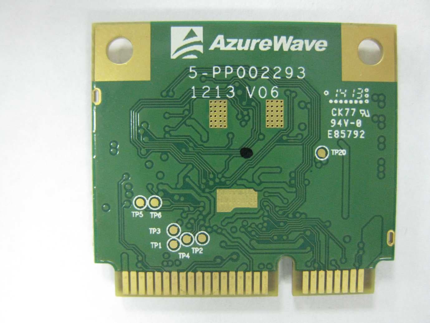
Click to zoom
Application Details
- Equipment Class
- DTS - Digital Transmission System
- Date of Grant
- May 19, 2015
- Application Purpose
- Original Equipment
- Date of Application
- May 19, 2015
- Equipment Note
- IEEE 802.11 a/b/g/n 2x2 MIMO, Bluetooth, BT LE
- Frequency Range
- 2412.00000000 - 2462.00000000
- Company
- Bang & Olufsen a/s
- Country
- Denmark
Documents & Files
Document Text
Text extracted from the exhibit documents filed with the FCC. Open a document above to read the original.
Users Manual
User manual for AW-AU397 module integration 1 Purpose The purpose of this document is to provide information on how to install the AW-AU397 module in B&O products. The AW-AU397 W-LAN module is only intended for integration into end host products by B&O authorised personnel only. Incorrect integration or use may infringe compliance rule meaning recertification is required. 2 Module description The module is an IEEE 802.11a/b/g/n 2X2 MIMO WLAN & Bluetooth module based on a Marvell chip. The module is designed to be plugged into a Mini PCI-E 52P connector, which contains all the interfaces and power connection. Additional the module has two UFL antenna connectors. See picture below. 3 Integration in B&O products The AW-AU397 module will be integrated in both audio and video products from B&O. A similar Mini PCI-E connector is used as interface and the antennas inside the product are connected to the UFL connectors at the module. 3.1 Module Integration Details Use the respective B&O build/assembly instructions for mounting and connecting the module into each B&O product type. This will ensure correct working of the module and will ensure it will not be collocated with any other transmitter/antenna if these instructions are followed. 3.2 Audio Devices In B&O audio products the AW-AU397 module can be installed in two different ways: 1. Stand-alone integration 2. Audio Streaming Engine mounted An example of stand-alone integration is shown in the following photos with the AW-AU397 module integrated in the BeoSound Moment end product: An example of the Audio Streaming Engine integration is shown in the following photo: 3.3 Audio Device Antennas The AW-WU397 module when integrated into Audio Devices will use the Tyco Puck antenna, part no.1513472-5, with a frequency range of 2,400 - 2,483.5 MHz & 5,150-5,875 MHz and peak gain of +3 dBi. If other radio systems are integrated in the product, it is required to keep minimum 20cm separation distance between any antenna from other radios and each of the antennas connected to AW-WU397. The module must not be integrated in portable devices to be used in direct contact with the body of the user or within 20cm of the body of the user under normal operating conditions. 3.4 Video Devices In Video Devices the AW-AU397 module will be mounted on a small interface board with a cable connection to the Video Engine. The interface board provides good flexibility for placing the module in an optimum position keeping antenna cables short. See picture. 3.4.1 Video Device Antenna The AW-AU397 module when integrated into video products will use the B&O BO AirWire antenna with a frequency range of 2,400-2,483.5 MHz & 5,150-5,875 MHz and a peak gain of +4.2 dBi. If other radio systems are integrated in the product, it is required to keep minimum 20cm separation distance between any antenna from other radios and each of the antennas connected to AW-WU397. The module must not be integrated in portable devices to be used in direct contact with the body of the user or within 20cm of the body of the user under normal operating conditions. 4 End Product Labelling A label is to be fitted to the exterior of all products containing the AW-AU397 module. The label must include the words “Contains FCC ID: TTUAW-AU397” (for FCC) or “Contains IC: 3775B-AWAU397” (for IC). Examples of B&O Audio and Video product labels and placement locations are in the following sections. 4.1 BeoSound Moment: 4.1.1 Label 4.1.2 Location 4.2 BeoVision Avant: 4.2.1 Label 4.2.2 Location FCC Compliance This device complies with Part 15 of the FCC Rules. Operation is subject to the following two conditions: (1) this device may not cause harmful interference, and (2) this device must accept any interference received, including interference that may cause undesired operation. FCC Caution: Any changes or modifications not expressly approved by the party responsible for compliance could void the user's authority to operate. This module must not be co-located or operating in conjunction with any other antenna or transmitter. This equipment complies with FCC radiation exposure limits set forth for an uncontrolled environment. This equipment should be installed and operated with minimum distance 20cm between the antenna & user’s body. In the United States, operation on channels 36-48 in the 5150-5250 MHz band is restricted to indoor-use only. If the FCC ID of the module is not visible when installed in the intended host equipment, then a permanently attached or marked label must be displayed on the exterior of the host equipment referring to the module FCC ID. Industry Canada Compliance This device complies with Industry Canada licence-exempt RSS standard(s). Operation is subject to the following two conditions: (1) this device may not cause interference, and (2) this device must accept any interference, including interference that may cause undesired operation of the device. Under Industry Canada regulations, this radio transmitter may only operate using an antenna of a type and maximum (or lesser) gain approved for the transmitter by Industry Canada. To reduce potential radio interference to other users, the antenna type and its gain should be so chosen that the equivalent isotropically radiated power (e.i.r.p.) is not more than that necessary for successful communication. This radio transmitter (IC ID: 3775B-AWAU397) has been approved by Industry Canada to operate with the antenna types listed below with the maximum permissible gain and required antenna impedance for each antenna type indicated. Antenna types not included in this list, having a gain greater than the maximum gain indicated for that type, are strictly prohibited for use with this device. 1) (Puck) Tyco; Part No. 1513472-5; Frequency Range: 2,400 - 2,483.5 MHz & 5,150 - 5,875 MHz; Gain (Max) +3 dBi, 2) (V100) B&O; Part No. BO AirWire; Frequency Range: 2,400 - 2,483.5 MHz & 5,150 - 5,875 MHz; Gain (Max) +4.2 dBi Please note that high-power radars are…
Text truncated - open the document above for the full version.
Cover Letter(s)
Bang & Olufsen a/s, Peter Bangs Vej 15, P.O. box 40, DK-7600 Struer Main phone no. [45] 96 84 11 22, Fax [45] 96 84 53 33, CVR-no. 41257911 www.bang-olufsen.dk Date: 12/07/2014 Telecommunication Certification Body UL VS Ltd Pavilion A Ashwood Park Ashwood Way Basingstoke Hampshire RG23 8BG United Kingdom Subject: Agency Letter, FCC ID: TTUAW-AU397 To whom it may concern This is to certify that Bang & Olufsen a/s authorises UL VS Ltd. to act on our behalf for the ap- plication of the AzureWave Module, FCC ID: TTUAW-AU397 to UL VS Ltd. Telecommunication Certification Body. We certify that we are not subject to a denial of Federal benefits, that include FCC benefits, pursuant to Section 5301 of the Anti-Drug Abuse Act of 1988, 21 U.S.C. § 862 because of a conviction for possession or distribution of a controlled substance. See 47 CFR 1.2002(b) for the definition of a "party" for these purposes. Yours faithfully, Jesper Flyholm Technical Project Manager
Cover Letter(s)
Bang & Olufsen a/s, Peter Bangs Vej 15, P.O. box 40, DK-7600 Struer Main phone no. [45] 96 84 11 22, Fax [45] 96 84 53 33, CVR-no. 41257911 www.bang-olufsen.dk Date: 03//26/2015 Telecommunication Certification Body UL VS Ltd Pavilion A Ashwood Park Ashwood Way Basingstoke Hampshire RG23 8BG United Kingdom Subject: Permanent Confidentiality Request Certification Application FCC ID: TTUAW-AU397 To whom it may concern Pursuant to Sections 0.457 and 0.459 of CFR 47, Bang & Olufsen a/s request that the following information, provided to support the FCC application for the AzureWave Module, FCC ID: TTUAW-AU397 be held permanently confidential: Schematics Block Diagrams Parts List Operational Description Tune Up Procedure The above material contains trade secrets not customarily released to public that are judged to have the potential to cause detriment to the applicant and provide unjustified benefits to its competitors. This information should not be available for public disclosure for an indefinite peri- od of time. Yours faithfully Jesper Flyholm Technical Project Manager
Cover Letter(s)
Bang & Olufsen a/s, Peter Bangs Vej 15, P.O. box 40, DK-7600 Struer Main phone no. [45] 96 84 11 22, Fax [45] 96 84 53 33, CVR-no. 41257911 www.bang-olufsen.dk Date: 12/07/2014 Telecommunication Certification Body UL VS Ltd Pavilion A Ashwood Park Ashwood Way Basingstoke Hampshire RG23 8BG United Kingdom Subject: Modular Approval, FCC ID: TTUAW-AU397 To whom it may concern Bang & Olufsen a/s request Modular Approval under 47 CFR §15.212 Modular transmit- ters, based on the below assessment. Modular Approval Requirements Yes No (a) The radio elements must have the radio frequen- cy circuitry shielded. Physical/discrete and tuning capacitors may be located external to the shield, but must be on the module assembly . X [please provide expansive de- scription if answer is ‘No’] (b) The module shall have buffered modulation/data input(s) (if such inputs are provided) to ensure that the module will comply with Part 15 Requirements with any type of input signal X [please provide expansive de- scription if answer is ‘No’] (c) The module shall have its own power supply regulation on the module. X [please provide expansive de- scription if answer is ‘No’] (d) The module must contain a permanently at- tached antenna, or contain a unique antenna con- nector, and be marketed and operated only with specific antenna(s), per Sections 15.203, 15.204(b), 15.204(c), 15.212(a), 2.929(b); X [please provide expansive de- scription if answer is ‘No’] Bang & Olufsen a/s, Peter Bangs Vej 15, P.O. box 40, DK-7600 Struer Main phone no. [45] 96 84 11 22, Fax [45] 96 84 53 33, CVR-no. 41257911 www.bang-olufsen.dk (e) The module must demonstrate compliance in a stand-alone configuration; X [please provide expansive de- scription if answer is ‘No’] (f) The module must be labelled with its permanent- ly affixed FCC ID label, or use an electronic display X [please provide expansive de- scription if answer is ‘No’] (g) The module must comply with all specific rules applicable to the transmitter. The grantee must pro- vide comprehensive instructions to explain compli- ance requirements; X [please provide expansive de- scription if answer is ‘No’] (h) The module must comply with RF exposure re- quirements. For any transmitters intended for use in portable devices, SAR compliance must be demon- strated to be independent of the host device. X [please provide expansive de- scription if answer is ‘No’] Yours faithfully, Jesper Flyholm Technical Project Manager
RF Exposure Info
Page 1 of 3 MPE Calculation - AW-AU397 FCC ID: TTUAW-AU397 The FCC requires that for mobile devices the calculated MPE be equal to or less than a given limit dependent on frequency at a distance of 20 cm from a device to the body of a user. The transmitter operation for the AW-AU397 covers WIFI 2412-2462MHz, 5180-5825MHz and BT 2402- 2480MHz operating bands. The WIFI and BT transmitters can transmit simultaneously. The following FCC Rule Parts are applicable: Part 1.1310 – Radiofrequency radiation exposure limits Part 2.1091(c) – Radiofrequency radiation exposure evaluation: mobile devices KDB447498 D01 v05 r02 Mobile and Portable Devices RF Exposure Procedures and Equipment Authorisation Policies MAXIMUM TRANSMITTER POWER CONSIDERATIONS Conducted power values are maximum Tune-Up values for the AW-AU397 Antenna gains are maximum specified. WIFI 5180-5825MHz Power conducted = 50.1mW (17.0 dBm) Antenna Gain: +4.5dBi EIRP = 21.5dBm = 141.3 mW WIFI 2412-2480MHz Power conducted = 63.1mW (18.0 dBm) Antenna Gain: +3.0dBi EIRP = 21.0dBm = 125.9 mW BT 2402 – 2480MHz Power conducted = 10.0mW (10.0 dBm) Antenna Gain: +3.0dBi EIRP = 13.0dBm = 20.0 mW Page 2 of 3 CALCULATION The following far field power density equation is applicable: S = EIRP/4 π R 2 Where S = Power density EIRP = Effective Isotropically Radiated Power (EIRP = P x G) P = Conducted Transmitter Power G = Antenna Gain (relative to an isotropic radiator) R = distance to the centre of radiation of the antenna For WIFI operation Considering 5180-5825MHz operation (maximum EIRP power) as worst case MPE: EIRP = 141.3mW R = 20cm Requirement From CFR §1.1310 (e) Table 1 - Limits for General Population/ Uncontrolled Exposure for 1,500-100,000MHz operation S req1 = 1.0 mW/cm 2 Calculation for 20cm safe distance S = EIRP/4 π R 2 S = 141.3/(12.56 x 20 2 ) = 141.3/ 5024 S 1 = 0.028 mW/cm 2 For BT operation Considering 2402 – 2480MHz operation (maximum power): EIRP = 20.0mW Page 3 of 3 R = 20cm Requirement From CFR §1.1310 (e) Table 1 - Limits for General Population/ Uncontrolled Exposure for 1,500-100,000MHz operation S req2 = 1.0 mW/cm 2 Calculation for 20cm safe distance S = EIRP/4 π R 2 S = 20/(12.56 x 20 2 ) = 20/ 5024 S 2 = 0.004 mW/cm 2 KDB447498 D01 v05 Section 7.2 SIMULTANEOUS TRANSMISSION CONSIDERATIONS Worst case summation of calculated MPE ratios for WIFI, and BT simultaneously transmitting transmitters is: ie: ΣMPE ratios = (S 1 / S req1 ) + (S 2 / S req2 ) = (0.028/1.0) + (0.004/1.0) = 0.032 Σ of MPE ratios<1.0, so in accordance with KDB447498 Section 7.2, simultaneous transmission test exclusion applies for the WIFI and BT transmitters. Conclusion The required 20cm RF exposure limits for General Population/ Uncontrolled Exposure will not be exceeded for the AW-AU397 using antennas having a maximum gain of +4.5 dBi for 5 GHz WIFI and +3.0dBi for 2.4GHz WIFI/ BT operation
Test Report
UL VS LTD Pavilion A, Ashwood Park, Ashwood Way, Basingstoke, Hampshire, RG23 8BG, UK Telephone: +44 (0)1256 312000 Facsimile: +44 (0)1256 312001 TEST REPORT Test Report No. : UL-RPT-RP10012646JD14A Manufacturer : Bang & Olufsen a/s Model No. : AW-AU397 FCC ID : TTUAW-AU397 Technology : Bluetooth – Low Energy Test Standard(s) : FCC Parts 15.207, 15.209(a) & 15.247 1. This test report shall not be reproduced in full or partial, without the written approval of UL VS LTD. 2. The results in this report apply only to the sample(s) tested. 3. The sample tested is in compliance with the above standard(s). 4. The test results in this report are traceable to the national or international standards. 5. Version 3.0 supersedes all previous versions. Date of Issue: 23 March 2015 Checked by: pp Sarah Williams Engineer, Radio Laboratory Issued by : John Newell Group Quality Manager UL VS LTD This laboratory is accredited by UKAS. The tests reported herein have been performed in accordance with its’ terms of accreditation. The Bluetooth ® word mark and logos are owned by the Bluetooth SIG, Inc. and any use of such marks by UL VS LTD is under licence. Other trademarks and trade names are those of their respective owners. TEST REPORT SERIAL NO: UL-RPT-RP10012646JD14A VERSION 3.0 ISSUE DATE: 23 MARCH 2015 Page 2 of 38 UL VS LTD This page has been left intentionally blank. TEST REPORT SERIAL NO: UL-RPT-RP10012646JD14A VERSION 3.0 ISSUE DATE: 23 MARCH 2015 UL VS LTD Page 3 of 38 Table of Contents 1. Customer Information ................................................................................................................ 4 2. Summary of Testing ................................................................................................................... 5 2.1. General Information 5 2.2. Summary of Test Results 5 2.3. Methods and Procedures 6 2.4. Deviations from the Test Specification 6 3. Equipment Under Test (EUT) .................................................................................................... 7 3.1. Identification of Equipment Under Test (EUT) 7 3.2. Description of EUT 7 3.3. Modifications Incorporated in the EUT 7 3.4. Additional Information Related to Testing 8 3.5. Support Equipment 9 3.6. Antenna 10 4. Operation and Monitoring of the EUT during Testing ............................................................11 4.1. Operating Modes 11 4.2. Configuration and Peripherals 11 5. Measurements, Examinations and Derived Results ...............................................................12 5.1. General Comments 12 5.2. Test Results 13 5.2.1. Transmitter AC Conducted Spurious Emissions 13 5.2.2. Transmitter Minimum 6 dB Bandwidth 16 5.2.3. Transmitter Maximum Peak Output Power 18 5.2.4. Transmitter Radiated Emissions – UAM Antenna 21 5.2.5. Transmitter Radiated Emissions – V100 Antenna 26 5.2.6. Transmitter Band Edge Radiated Emissions – UAM Antenna 31 5.2.7. Transmitter Band Edge Radiated Emissions – V100 Antenna 34 6. Measurement Uncertainty ........................................................................................................37 7. Report Revision History ...........................................................................................................38 TEST REPORT SERIAL NO: UL-RPT-RP10012646JD14A VERSION 3.0 ISSUE DATE: 23 MARCH 2015 Page 4 of 38 UL VS LTD 1. Customer Information Company Name: Bang & Olufsen a/s Address: Peter Bangs Vej 15 7600 Struer Denmark TEST REPORT SERIAL NO: UL-RPT-RP10012646JD14A VERSION 3.0 ISSUE DATE: 23 MARCH 2015 UL VS LTD Page 5 of 38 2. Summary of Testing 2.1. General Information Specification Reference: 47CFR15.247 Specification Title: Code of Federal Regulations Volume 47 (Telecommunications): Part 15 Subpart C (Intentional Radiators) – Section 15.247 Specification Reference: 47CFR15.207 and 47CFR15.209 Specification Title: Code of Federal Regulations Volume 47 (Telecommunications): Part 15 Subpart C (Intentional Radiators) – Sections 15.207 and 15.209 Site Registration: 209735 Location of Testing: UL VS LTD, Unit 3 Horizon, Wade Road, Kingsland Business Park, Basingstoke, Hampshire, RG24 8AH, United Kingdom Test Dates: 23 January 2014 to 27 February 2014 2.2. Summary of Test Results FCC Reference (47CFR) Measurement Result Part 15.207 Transmitter AC Conducted Emissions Part 15.247(a)(2) Transmitter Minimum 6 dB Bandwidth Part 15.247(e) Transmitter Power Spectral Density Note 1 Part 15.247(b)(3) Transmitter Maximum Peak Output Power Part 15.247(d)/15.209(a) Transmitter Radiated Emissions Part 15.247(d)/15.209(a) Transmitter Band Edge Radiated Emissions Key to Results = Complied = Did not comply Note(s): 1. In accordance with FCC KDB 558074 Section 10.1, PSD is not required if the maximum conducted output power is less than the PSD limit of 8 dBm / 3 kHz. The PSD level is therefore deemed to be equal to the measured total output power. 2. KDB558074 v03 r01 was used at the time of testing, as this was the latest version of KDB available. This testing has subsequently been reviewed, to ensure that the test methods comply with the latest requirements of KDB558074 v03 r02, 05 June 2014. TEST REPORT SERIAL NO: UL-RPT-RP10012646JD14A VERSION 3.0 ISSUE DATE: 23 MARCH 2015 Page 6 of 38 UL VS LTD 2.3. Methods and Procedures Reference: ANSI C63.4 (2009) Title: American National Standard for Methods of Measurement of Radio-Noise Emissions from Low-Voltage Electrical and Electronic Equipment in the Range of 9 kHz to 40 GHz Reference: ANSI C63.10 (2009) Title: American National Standard for Testing Unlicensed Wireless Devices Reference: KDB 558074 D01 DTS Meas Guidance v03r02 June 5, 2014 Title: Guidance for Performing Compliance Measurements on Digital Transmission Systems (DTS) Operating Under §15.247 2.4. Deviations from the Test Specification For the measurements contained within this test report, there were no deviations from, additions to, or exclusions from the test specification identified above. TEST REPORT SE…
Text truncated - open the document above for the full version.
Test Report
UL VS LTD Pavilion A, Ashwood Park, Ashwood Way, Basingstoke, Hampshire, RG23 8BG, UK Telephone: +44 (0)1256 312000 Facsimile: +44 (0)1256 312001 TEST REPORT Test Report No. : UL-RPT-RP10012646JD06A Manufacturer : Bang & Olufsen a/s Model No. : AW-AU397 FCC ID : TTUAW-AU397 Technology : WLAN (802.11 b/g/n) Test Standard(s) : FCC Parts 15.207, 15.209(a) & 15.247 1. This test report shall not be reproduced in full or partial, without the written approval of UL VS LTD. 2. The results in this report apply only to the sample(s) tested. 3. The sample tested is in compliance with the above standard(s). 4. The test results in this report are traceable to the national or international standards. 5. Version 4.0 supersedes all previous versions. Date of Issue: 23 March 2015 Checked by: pp Ian Watch Senior Engineer, Radio Laboratory Issued by : John Newell Quality Manager, UL VS LTD This laboratory is accredited by UKAS. The tests reported herein have been performed in accordance with its terms of accreditation. TEST REPORT SERIAL NO: UL-RPT-RP10012646JD06A VERSION 4.0 ISSUE DATE: 23 MARCH 2015 Page 2 of 69 UL VS LTD This page has been left intentionally blank. TEST REPORT SERIAL NO: UL-RPT-RP10012646JD06A VERSION 4.0 ISSUE DATE: 23 MARCH 2015 UL VS LTD Page 3 of 69 Table of Contents 1. Customer Information ................................................................................................................ 4 2. Summary of Testing ................................................................................................................... 5 2.1. General Information 5 2.2. Summary of Test Results 5 2.3. Methods and Procedures 6 2.4. Deviations from the Test Specification 6 3. Equipment Under Test (EUT) .................................................................................................... 7 3.1. Identification of Equipment Under Test (EUT) 7 3.2. Description of EUT 7 3.3. Modifications Incorporated in the EUT 7 3.4. Additional Information Related to Testing 8 3.5. Support Equipment 9 3.6. Antenna 10 4. Operation and Monitoring of the EUT during Testing ............................................................11 4.1. Operating Modes 11 4.2. Configuration and Peripherals 11 5. Measurements, Examinations and Derived Results ...............................................................13 5.1. General Comments 13 5.2. Test Results 14 5.2.1. Transmitter AC Conducted Spurious Emissions 14 5.2.2. Transmitter Minimum 6 dB Bandwidth 18 5.2.3. Transmitter Power Spectral Density 28 5.2.4. Transmitter Radiated Emissions – UAM Antenna 36 5.2.5. Transmitter Radiated Emissions – V100 Antenna 43 5.2.6. Transmitter Band Edge Radiated Emissions – UAM Antenna 50 5.2.7. Transmitter Band Edge Radiated Emissions – V100 Antenna 59 6. Measurement Uncertainty ........................................................................................................68 7. Report Revision History ...........................................................................................................69 TEST REPORT SERIAL NO: UL-RPT-RP10012646JD06A VERSION 4.0 ISSUE DATE: 23 MARCH 2015 Page 4 of 69 UL VS LTD 1. Customer Information Company Name: Bang & Olufsen a/s Address: Peter Bangs Vej 15 7600 Struer Denmark TEST REPORT SERIAL NO: UL-RPT-RP10012646JD06A VERSION 4.0 ISSUE DATE: 23 MARCH 2015 UL VS LTD Page 5 of 69 2. Summary of Testing 2.1. General Information Specification Reference: 47CFR15.247 Specification Title: Code of Federal Regulations Volume 47 (Telecommunications): Part 15 Subpart C (Intentional Radiators) - Section 15.247 Specification Reference: 47CFR15.207 and 47CFR15.209 Specification Title: Code of Federal Regulations Volume 47 (Telecommunications): Part 15 Subpart C (Intentional Radiators) - Sections 15.207 and 15.209 Site Registration: 209735 Location of Testing: UL VS LTD, Unit 3 Horizon, Wade Road, Kingsland Business Park, Basingstoke, Hampshire, RG24 8AH, United Kingdom Test Dates: 28 November 2013 to 08 January 2014 2.2. Summary of Test Results FCC Reference (47CFR) Measurement Result Part 15.207 Transmitter AC Conducted Emissions Part 15.247(a)(2) Transmitter Minimum 6 dB Bandwidth Part 15.35(c) Transmitter Duty Cycle Note 1 Part 15.247(e) Transmitter Power Spectral Density Part 15.247(d) & 15.209(a) Transmitter Radiated Emissions Part 15.247(d) & 15.209(a) Transmitter Band Edge Radiated Emissions Key to Results = Complied = Did not comply Note(s): 1. Duty cycle was measured and found to be >98%, therefore no plots have been included within this report. Duty cycle measurement plots are archived on the UL VS LTD IT server and available for inspection if required. 2. KDB558074 v03 r01 was used at the time of testing, as this was the latest version of KDB available. This testing has subsequently been reviewed, to ensure that the test methods comply with the latest requirements of KDB558074 v03 r02, 05 June 2014. TEST REPORT SERIAL NO: UL-RPT-RP10012646JD06A VERSION 4.0 ISSUE DATE: 23 MARCH 2015 Page 6 of 69 UL VS LTD 2.3. Methods and Procedures Reference: ANSI C63.4 (2009) Title: American National Standard for Methods of Measurement of Radio-Noise Emissions from Low-Voltage Electrical and Electronic Equipment in the Range of 9 kHz to 40 GHz Reference: ANSI C63.10 (2009) Title: American National Standard for Testing Unlicensed Wireless Devices Reference: KDB 558074 D01 DTS Meas Guidance v03r02 June 5, 2014 Title: Guidance for Performing Compliance Measurements on Digital Transmission Systems (DTS) Operating Under 15.247 Reference: KDB 662911 D01 v02r01 October 31, 2013 Title: Emissions Testing of Transmitters with Multiple Outputs in the Same Band 2.4. Deviations from the Test Specification For the measurements contained within this test report, there were no deviations from, additions to, or exclusions from the test specification identified above. TEST REPORT SERIAL NO: UL-RPT-RP10012646JD06A VERSION 4.0 ISSUE DATE: 23 MARCH 2015 UL VS LTD Page 7 of 69 3. Equipment Under Tes…
Text truncated - open the document above for the full version.
Test Report
Test report No. : 10012646H-R4 Page : 1 of 13 Issued date : November 20, 2014 Revised date : April 23, 2015 FCC ID : TTUAW-AU397 IC Number : 3775B-AWAU397 UL Japan, Inc. Ise EMC Lab. 4383-326 Asama-cho, Ise-shi, Mie-ken 516-0021 JAPAN Telephone : +81 596 24 8999 Facsimile : +81 596 24 8124 13-EM-F0429 RADIO TEST REPORT Test Report No. : 10012646H-R4 Applicant : Bang & Olufsen a/s Type of Equipment : IEEE 802.11a/b/g/n 2 x 2 MIMO WLAN and Bluetooth module Model No. : AW-AU397 FCC ID : TTUAW-AU397 IC Number : 3775B-AWAU397 Test regulation : FCC Part 15 Subpart C: 2015 RSS-Gen Issue 4: 2014 RSS-210 Issue 8: 2010 +Amendment 1: 2015 (Average Output Power test only) Test Result : Complied 1. This test report shall not be reproduced in full or partial, without the written approval of UL Japan, Inc. 2. The results in this report apply only to the sample tested. 3. This sample tested is in compliance with the above regulation. 4. The test results in this report are traceable to the national or international standards. 5. This test report covers Radio technical requirements. It does not cover administrative issues such as Manual or non-Radio test related Requirements. (if applicable) 6. This report is a revised version of 10012646H-R3. 10012646H-R3 is replaced with this report. Date of test: November 19, 2014 Representative test engineer: Hiroshi Kukita Engineer Consumer Technology Division Approved by: Takahiro Hatakeda Leader Consumer Technology Division Test report No. : 10012646H-R4 Page : 2 of 13 Issued date : November 20, 2014 Revised date : April 23, 2015 FCC ID : TTUAW-AU397 IC Number : 3775B-AWAU397 UL Japan, Inc. Ise EMC Lab. 4383-326 Asama-cho, Ise-shi, Mie-ken 516-0021 JAPAN Telephone : +81 596 24 8999 Facsimile : +81 596 24 8124 REVISION HISTORY Original Test Report No.: 10012646H Revision Test report No. Date Page revised Contents - (Original) 10012646H November 20, 2014 - - 1 10012646H-R1 March 31, 2015 All pages (header) Added IC Number 1 10012646H-R1 March 31, 2015 1 Deleted NVLAP logo and its related note 1 10012646H-R1 March 31, 2015 1, 5 Updated FCC15 standard version and added RSS standard information 1 10012646H-R1 March 31, 2015 5 Updated RSS standard in table in clause 3.2 1 10012646H-R1 March 31, 2015 7 Deleted a note for Operating mode 1 10012646H-R1 March 31, 2015 11, 12 Corrected test data 2 10012646H-R2 April 3, 2015 5 Corrected ANSI C63.4 version 3 10012646H-R3 April 22, 2015 7 Added explanatory note for worst mode 4 10012646H-R4 April 23, 2015 7 Added explanatory note for worst mode Test report No. : 10012646H-R4 Page : 3 of 13 Issued date : November 20, 2014 Revised date : April 23, 2015 FCC ID : TTUAW-AU397 IC Number : 3775B-AWAU397 UL Japan, Inc. Ise EMC Lab. 4383-326 Asama-cho, Ise-shi, Mie-ken 516-0021 JAPAN Telephone : +81 596 24 8999 Facsimile : +81 596 24 8124 CONTENTS PAGE SECTION 1: Customer information ......................................................................................................... 4 SECTION 2: Equipment under test (E.U.T.) ........................................................................................... 4 SECTION 3: Test specification, procedures & results ............................................................................ 5 SECTION 4: Operation of E.U.T. during testing .................................................................................... 7 SECTION 5: Antenna Terminal Conducted Tests .................................................................................. 9 APPENDIX 1: Data of EMI test .............................................................................................................. 10 Average Output Power ...................................................................................................................... 10 APPENDIX 2: Test instruments ............................................................................................................. 13 Test report No. : 10012646H-R4 Page : 4 of 13 Issued date : November 20, 2014 Revised date : April 23, 2015 FCC ID : TTUAW-AU397 IC Number : 3775B-AWAU397 UL Japan, Inc. Ise EMC Lab. 4383-326 Asama-cho, Ise-shi, Mie-ken 516-0021 JAPAN Telephone : +81 596 24 8999 Facsimile : +81 596 24 8124 SECTION 1: Customer information Company Name : Bang & Olufsen a/s Address : Peter Bangs Vej 15 7600 Struer Denmark SECTION 2: Equipment under test (E.U.T.) 2.1 Identification of E.U.T. Type of Equipment : IEEE 802.11a/b/g/n 2 x 2 MIMO WLAN and Bluetooth module Model No. : AW-AU397 Serial No. : Refer to Section 4, Clause 4.2 Receipt Date of Sample : August 8, 2014 Modif…
Text truncated - open the document above for the full version.
Contact Information
Applicant
Marlon Schrimpf(Product Compliance Lead)
Technical Contact
Bang & Olufsen a/sJesper Flyvholm
[email protected]+4596844782
Peter Bangs Vej 15 · Struer · United Kingdom
Test Firm
UL VS LtdDarren Rust
Technical Specifications
| # | Rule Parts | Frequency Range | Power Output |
|---|---|---|---|
| 2 | 15C | 2.41 GHz - 2.46 GHz | 59.00 mW |
Other Applications from Bang & Olufsen a/s
TTUBEOGRACEL
Sep 25, 2025Bluetooth Earphone
Equipment Class
DSS - Part 15 Spread Spectrum TransmitterTTUBEOPLAYH100
Jun 03, 2024Wireless Headphones
Equipment Class
DTS - Digital Transmission System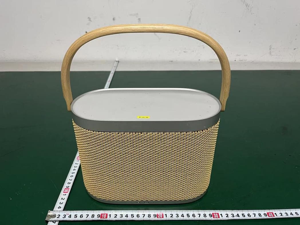
TTUBSA5
Mar 28, 2023Wireless Speaker
Equipment Class
DTS - Digital Transmission System
TTUBSTHEATRE
Jun 02, 2022Sound Bar
Equipment Class
DTS - Digital Transmission System
TTUBEOPLAYPL
Mar 10, 2021Wireless Gaming Headphones
Equipment Class
NII - Unlicensed National Information Infrastructure TX